Abstract
Traditional guidance and control systems often treat guidance and control systems separately, leading to reduced interception accuracy and responsiveness, especially during high-speed terminal trajectories. These limitations are further exacerbated in autonomous underwater vehicles (AUVs) due to unknown wave/current disturbances, harsh underwater acoustic conditions, and limited sensor capabilities. To address these challenges, this paper studies an integrated guidance and control (IGC) design for AUVs intercepting maneuvering targets with unknown disturbances and unmeasurable system states. The IGC model is derived based on the relative motion equations between the AUV and the target, incorporating the lateral dynamics of the AUV. A model transformation is introduced to synthesize external disturbances with unmeasurable states, extending the resultant disturbance to a new system state. A finite-time convergent extended state observer (ESO) is thus designed for the transformed system to estimate the unknown signals. Using these estimates from the observer, a finite-time event-triggered sliding mode controller is developed, ensuring finite-time convergence of system errors to an adjustable residual set, as rigorously proven through Lyapunov stability analysis. Simulation results demonstrate the superiority of the proposed method in achieving higher interception accuracy and faster response compared to traditional guidance and control approaches with unknown disturbances and unmeasurable states.
1. Introduction
In the field of ocean engineering, high-speed AUVs play an important role in intercepting underwater targets such as anti-ship AUVs or missiles [1,2,3,4]. A key factor influencing interception accuracy is the guidance and control system. Traditional approaches treated the guidance control systems as separate entities, where the guidance system computed required guidance commands based on relative motion dynamics, by which the control system generated the actual control rudder inputs to execute the interception. While these methods have been extensively studied [5,6,7,8,9,10,11], they overlooked the mutual coupling and hysteresis between the guidance and control systems. This limitation becomes particularly problematic during high-speed terminal trajectories, where rapid attitude changes lead to larger miss distances and reduced hitting accuracy.
IGC addresses these challenges by unifying the design of guidance and control systems. By directly generating control commands based on relative motion dynamics and dynamic model characteristics [12,13,14], IGC enhances both interception accuracy and responsiveness. Initially developed for missile flight control systems [15], IGC has since been extended to address nonlinear disturbances [16], modeling errors [17], and composite disturbances [18]. Notable advancements include finite-time estimation of disturbances using second-order sliding mode methods [18], non-singular terminal sliding mode control [19], parallel control [20,21], and bounded control strategies to prevent actuator saturation [22].
Despite these advances, most IGC schemes are tailored for missiles and aircraft, which are not directly applicable to AUVs operating in complex marine environments. Challenges specific to AUVs include unknown wave/current disturbances, harsh underwater acoustic conditions, and limited sensor capabilities [1,23]. For instance, AUVs cannot directly measure sideslip angle or line-of-sight (LOS) velocity due to the fixed acoustic transducer array firmly attached to the shell, unlike missiles and aircrafts that rely on infrared and radio sensors. Additionally, the short interception window and high-speed maneuverability of underwater targets exacerbate the need for fast response systems. Failure to account for guidance-control hysteresis can lead to significant miss distances [24,25,26,27], underscoring the necessity of IGC designs for AUVs.
The motivation of this study stems from the critical need to enhance the interception accuracy and responsiveness of AUVs in complex marine environments. Existing solutions often involve designing observers to estimate unmeasurable signals [28,29,30,31], but these methods typically ignore the impact of external disturbances on estimation accuracy. Furthermore, Extended state observers (ESOs) have demonstrated robustness in estimating unknown disturbances and target maneuvers [32,33,34,35], which lumped the unknown signals together as new states that can be estimated online, but these methods developed for aircraft guidance and control systems cannot be directly applied to AUVs. These gaps in the literature motivate the development of a novel IGC framework for AUVs.
Motivated by the aforementioned challenges, this paper proposes an IGC design for AUVs intercepting maneuvering targets with unknown disturbances and unmeasurable system states. A finite-time ESO is constructed to estimate the unmeasured signals, including disturbances, sideslip angle, LOS velocity, and target maneuvers, by which an event-triggered sliding mode controller is then designed to realize a successful interception. Meanwhile, event-triggered control strategies [36,37] reduce unnecessary actuator activations while preserving system stability and performance, which aligns with the energy-efficiency requirements of the AUVs. The contributions of this paper are mainly threefold:
- State Transformation: Accounting for external disturbances and unmeasurable states, a novel state transformation is proposed to convert the AUV IGC model with unmatched disturbances into a system with matched disturbances, thereby facilitating effective observer and controller design.
- Finite-Time ESO Design: Based on the transformed system, a finite-time ESO is developed to estimate the unknown states and disturbances in finite-time, ensuring robustness against external perturbations.
- Event-Triggered IGC Controller: Using the ESO estimates, the IGC design is proposed such that a successful interception of the incoming target is realized with unknown disturbances and the unmeasurable sideslip angle and LOS velocity. The event-triggering mechanism reduces communication and actuator burdens, enhancing system efficiency.
The proposed method demonstrates superior performance in simulation studies, achieving higher interception accuracy and faster response compared to traditional guidance and control approaches with unknown disturbances and unmeasurable states.
The remainder of this paper is organized as follows. Section 2 formulates the IGC design problem and provides necessary preliminaries. Section 3 details the state transformation, finite-time ESO design, and controller development. Simulation results and discussions are presented in Section 4, followed by conclusions in Section 5.
2. Preliminaries
Problem Formulation
Notice that the depth range of the target varies very little in the terminal phase; it is assumed that the AUV and the target are moving in the same plane. The interception geometry between the AUV and the target is illustrated in Figure 1, where A and denote the positions of the AUV and target, and the axes of x and y are north and east directions of the Earth-fixed frame, respectively. The reference line is parallel to the x axis with the same direction. Additionally, q is the LOS angle, is the ballistic inclination angle, is the target course angle, is the advanced angle of the AUV velocity, and is the advanced angle of the target velocity. The starting edge of all the angles is , such that the positive direction of the angle is anti-clockwise from to the adjacent side; r is the relative distance between the AUV and the target; and is the maximum allowable miss, i.e., successful target interception is achieved when .
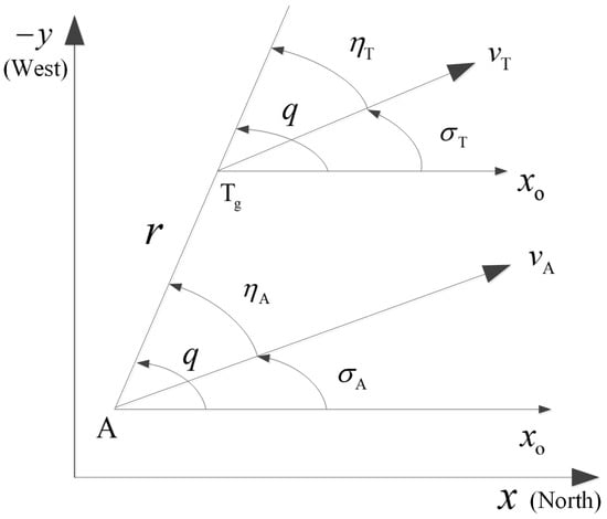
Figure 1.
Interception geometry between the AUV and target.
According to the relative motion relationship between the AUV and the target shown in Figure 1, the AUV velocity and the target velocity are decomposed along the LOS direction and its normal direction, respectively, such that the relative motion equations are given by
Notice that the AUV velocity and the target velocity are almost constants in the end trajectory. Thus, we obtain
Taking the time-derivative of (1) yields
The disturbance term caused by the target manuevering is defined as
where the first term denotes the measurement error of q and , and the second term is the unmeasurable target motion information.
According to the results in [38,39,40], the dynamic model equations of the AUV lateral channel are given by
In the above, , where is the yaw and is the sideslip angle; is the yaw velocity and is the rudder control input to be designed. Furthermore, the constant m is the mass of the AUV; the constant is the moment of inertia, the constants are the hydrodynamic coefficients, the constant , the constants are the correlation coefficients, and the constant T is the end trajectory thrust in the longitudinal direction of the AUV.
Define the state variables and , and combining Equations (7), (8) and (10), the IGC model of the AUV is given by
where , , , , , , , ; , ; , , .
It is then obtained from (2) that
Define and ; using (11), we obtain
where
and is the system output vector measured by the equipped acoustic transducer array and inertial navigation system.
After the above derivation, the control objective reduces to enable the design of the rudder control input with the available system outputs , i.e., and are unmeasurable, such that the state vector is stabilized.
3. Main Results
Considering the modeling error and external disturbances in the system, (13) is rewritten as
where , are unknown nonlinearities, including modeling error and the external disturbances of each system state.
3.1. Model Transformation
It is noted from (14) that the LOS velocity and the sideslip angle are not available, leading to unknown and . Therefore, an observer needs to be designed to achieve the online estimation of and . Since , , and are unmatched disturbances in the system, to facilitate the design of the observer and controller, a novel state transformation method is proposed.
The primary objective of this transformation is to convert the original system affected by unmatched disturbances into an equivalent system with matched disturbances. Specifically, the proposed transformation enables the development of an observer capable of accurately estimating the unknown states, and , and the resultant external disturbances, thereby providing the necessary information for the IGC design. The subsequent sections of this paper will detail the formulation of this transformation and its integration into the overall IGC framework.
Using the measurable yaw velocity , the input transformation is given by
It is observed from (16) that the unknown disturbances exist in the last three equations. By lumping the disturbances with system states, the state transformation is given by
Substituting the last equation of (16) into yields
According to (17), we obtain and , and then (20) becomes
where the lumped disturbance of the transformed system is given by
Using the input transformation (15) and the state transformation (17), the system (14) with unmatched disturbances can be transformed as
where , , , .
Accordingly, the control objective reduces to enable the designing of u to stabilize the states of (22) with unknown , , , and . The actual rudder control input can be obtained by using (15) and (17). The IGC design diagram is shown in Figure 2.
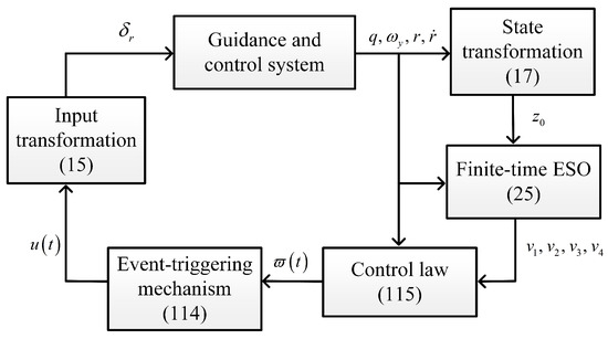
Figure 2.
IGC design diagram.
In order to facilitate the derivation and analysis of the ESO, the following assumptions, definitions, and lemmas are given.
Assumption 1.
The lumped disturbance and its derivative are bounded, such that there exists a known constant satisfying .
Remark 1.
Since the system modeling omitted the higher-order small quantities, and the target has limited maneuvering ability, it is determined that ; therefore, Assumption 1 is reasonable.
Assumption 2.
The value of the sideslip angle β is very small during the interception trajectory. It is assumed that , .
Assumption 3.
Using Assumptions 1 and 2, it is determined that the disturbed sideslip angle signal is bounded, and its estimation can be bounded a priori by the ESO design. It is consequently assumed that there exists a known constant satisfying with the estimated error .
Definition 1
([41,42]). Consider the following system:
where is a continuous function of on an open neighborhood of the origin. , there exists a continuous function , such that the solution of (23) satisfies and , ; and , ; then, will converge from to in finite time .
Lemma 1
([41]). Consider the system described by (23); if there exist continuously differentiable positive definite functions , positive real numbers and , and the open neighborhood containing the origin, such that
then it is determined that the system (23) is finite-time stable. In addition, the system (23) is globally finite-time stable with the convergence time, satisfying if and is radially unbounded.
Lemma 2
Definition 2
([45,46]). Define the function vector . For any , there exist a constant vector , , , and a constant , such that
then is said to have a homogeneous degree k with respect to the dilation .
Definition 3
([45,46]). Define a continuous scalar function , for any , as follows: if there exist and the dilation , , , such that
then is said to have a homogeneous degree k with respect to the dilation .
Lemma 3
Lemma 4
([49]). For any , , , , if the following relationship holds:
Lemma 5
([50]). For any , , , the following relationship holds:
3.2. Finite-Time ESO Design
In this section, a finite-time ESO is designed to quickly estimate the unknown states of the system (22) with matched disturbances, by which the rudder control input is designed. It is noted from (22) that the system states are unknown due to the disturbances () and unmeasurable variables (, ), and only is a known signal among the state variables. Since needs to be extended as a new state for the ESO design, it follows from (21) that the extended system state satisfies . Thus, (22) is rewritten as
Let , denote the estimations of in (24); then, the finite-time ESO is designed as
where , , , , , and and are selected such that , .
Let denote the estimation error vector of the ESO, by which (26) equals to
where the vector fields are given by
Define the constant and the error vector
Construct the Lyapunov function
where the symmetric positive-definite matrix can be obtained by solving the following equation:
where is the unit diagonal matrix; the design parameters , of (26) are selected such that (33) is Hurwitz.
The convergence analysis of the ESO given by (25) is summarized in Theorem 1.
Theorem 1.
Consider the transformed AUV IGC model (14) satisfying Assumptions 1–3; the design parameters are selected as , , , , ; , . Then, the estimation error of the finite-time ESO (25) will converge to the set U defined by (34) in finite time .
where ,
where is the Lie derivative of V with respect to the vector field , i.e., the time derivative of V along the system:
where is the Lie derivative of V with respect to vector field , i.e., the time derivative of V along the system:
In addition, the convergence time satisfies
where , , , and is the Gaussian hypergeometric function [51,52].
Proof.
The result of (39) shows that along (27) can be decomposed into the sum of the Lie derivatives of V with respect to the vector fields , , and , such that the three Lie derivatives on the right side of (39) can be studied separately.
For , combining (28) and expanding (35) yield
Construct the Lyapunov function as follows:
Notice that has the same expression as V in (31), while the Lie derivatives are along different systems. The subscript emphasizes that is a Lyapunov function of the system in (35) and (41).
According to [46], the system defined by (35) and (41) has a negative degree of homogeneity with respect to the dilation . It is then verified from Definition 3 that the scalar functions and have degrees of homogeneity and with respect to the dilation ; using Lemma 4.2 of [48] yields
where , .
Furthermore, according to Theorem 1 of [53], we have
where is the minimum value of the ESO design parameter given by (25), and is the largest eigenvalue of the positive-definite matrix .
Define the Lyapunov function
Notice that has the same expression as V in (31); the subscript emphasizes that is a Lyapunov function of in (36) and (46).
According to [46], the system defined by (36) and (46) has a negative degree of homogeneity with respect to the dilation . It is then verified from Definition 3 that the scalar functions and have degrees of homogeneity and with respect to the dilation ; using Lemma 4.2 of [48] yields
where , .
It can be seen from (30) that
Thus, (53) is equivalent to
Let denote the minimum eigenvalue of the positive-definite matrix ; we have
Remark 2.
It should be noted that is bounded because the AUV and the target have limited velocities. Additionally, the interception concludes as , which means during the interception; therefore, is bounded [54].
Since , select the design parameters , to satisfy
such that
Therefore, the Lyapunov function V can converge from any initial value to in finite-time , satisfying
Since , select the design parameters , to satisfy , and define the constant
Therefore, the Lyapunov function V can converge from the initial value to the set
in finite time , satisfying
Theorem 1 shows that by adjusting the design parameters , the estimation error vector can converge in finite time within the residual set U defined by (34). It is further shown that when the design parameters are selected to be large enough, the observation error vector can converge to in finite time, which is summarized in Theorem 2.
Theorem 2.
Consider the AUV IGC model (14) satisfying Assumptions 1–3, and the design parameters are selected according to Theorem 1; if the design parameters further satisfy , , , , , where the specific definitions of are shown in (34), then the observation error vector of the ESO (25) will converge to 0 in finite time , and the convergence time satisfy
Proof.
Define the Lyapunov function , and taking the time-derivative of along (26) yields
According to (54), (69), and (34), we have . It is obtained that in (75) by choosing the design parameter
by which (75) is rewritten as
with .
Therefore, can converge from the initial value to zero in finite-time satisfying
The analysis of (77) and (78) implies that in finite-time , such that the first equation of (26) is rewritten as
which is obtained by passing the signal
through a low-pass filter based on the equivalent control theory [55], i.e., the low-frequency part of the sign function is preserved.
Define the Lyapunov function , and taking the time-derivative of along (81) yields
According to (54), (69) and (34), we have , . It is observed that in (82) by choosing the design parameter
by which (82) is rewritten as
where and .
Therefore, by combining (84) with Lemma 1, we obtain that the Lyapunov function can converge from the initial value to zero in finite time , satisfying
Similar to the analytical steps of (79) to (81), we obtain , such that the third equation of (26) equals to
Define the Lyapunov function , and taking the time-derivative of along (87) yields
According to (54), (69), and (34), we have . It is observed that in (88) by choosing the design parameter
by which (88) is rewritten as
where and .
Therefore, by combining (90) with Lemma 1, we obtain that the Lyapunov function can converge from the initial value to zero in finite time , satisfying
Similarly to the analytical steps of (79) to (81), we obtain , such that the fourth equation of (26) equals to
Define the Lyapunov function , and taking the time-derivative of along (93) yields
According to (54), (69) and (34), we have . It is observed that in (94) by choosing the design parameter
by which (94) is rewritten as
where and .
Therefore, by combining (96) with Lemma 1, we obtain that the Lyapunov function can converge from the initial value to zero in finite time , satisfying
Similarly to the analytical steps of (79) to (81), we obtain , such that the last equation of (26) equals to
Define the Lyapunov function , and taking the time-derivative of along (99) yields
It is observed that in (100) by choosing the design parameter
by which (100) is rewritten as
where and .
Therefore, by combining (102) with Lemma 1, we obtain that the Lyapunov function can converge from the initial value to zero in finite-time , satisfying
In summary, the ESO estimation errors converge to zero in finite time . □
3.3. Global Sliding Mode Function Construction
Since the designed ESO is finite-time convergent, satisfying the separation principle [49], the output feedback controller is designed in this part using the ESO estimations.
Define a nonlinear time function as follows:
where the design parameters , ; , ; and the design parameters are selected such that
is Hurwitz, where P is the Laplace operator.
Notice that the introduction of is to reduce the reaching mode of the sliding surface, such that the closed-loop system stays at the sliding mode motion stage from the initial moment, which can enhance the robustness of the system [56]. In order to achieve this goal, the selection of the design parameters should meet the following conditions:
1. , i.e.,
2. There exists , , such that and , i.e.,
Therefore, for a given set of design parameters , , , and , the values of and can be obtained by (110), and thus, the sliding mode surface can be constructed by (106). Specifically, the nonlinear time function defined by (111) satisfies the above global sliding mode conditions.
In addition, to ensure that is globally differentiable, the following condition must hold:
3.4. Event-Triggered Control Input
Define the measurement error as , the event-triggering mechanism is designed as
where is the subscript that records the triggering time, is the initial time, the design parameters C, D, , and .
3.5. Stability Analysis
The stability analysis of the proposed IGC design is summarized in Theorem 3.
Theorem 3.
Considering the AUV IGC model (14) satisfying Assumptions 1–3, the output feedback event-triggered sliding mode controller given by (25), (114), (115) and (116) guarantees the finite-time stability of the closed-loop system; the state error can converge to an arbitrarily small adjustable neighborhood containing the origin in finite time.
Proof.
Define the Lyapunov function
Applying Lemma 5, we obtain
Select the appropriate design parameter such that and define
as the error caused by the ESO estimation; then, (122) can be rewritten as
where using (117).
According to Theorems 1 and 2, the error E is globally bounded and converges to zero in finite time. In addition, according to (114) and (115), the measurement error satisfies
which means that is globally bounded.
Therefore, the closed-loop system is finite-time stable and the errors converge to the set
where , .
The convergence time satisfies
Combining (125) with (105), (106) and (111), it can be seen that the system state eventually converges to a non-zero residual set containing the origin, which can be made arbitrarily small to satisfy the required control performance by adjusting the design parameters and .
Notice that . It is proven that converges to an adjustable neighborhood about the origin in finite time, i.e., the AUV can intercept the target in finite time. Since all signals are globally bounded, by Theorems 1 and 2 of [57], the inter-event interval of the event-triggering mechanism (114) is lower bounded by positive constants excluding the Zeno phenomenon. □
4. Simulations
Considering the AUV lateral dynamics in [39], the initial states are given by , , and ; the initial position of the incoming target is , , ; the unmeasurable target maneuvering angular velocity is ; and the x and y coordinates of the target are measured with random errors satisfying the uniform distribution of .
The design parameters of the ESO are given by , , , , , and ; , , , and . The controller design parameters are given by , , , , , , , , , and ; the control rudder is constrained as ; and the event-triggering mechanism design parameters are given by , , , and .
In order to verify the effectiveness of the proposed method, simulation comparisons were carried out with the traditional proportional guidance, trail guidance, and fixed advanced angle guidance (the advanced angle is ). The simulation results are shown in Figure 3, Figure 4, Figure 5, Figure 6 and Figure 7. It can be seen from Figure 3 and Figure 4 that the states of the AUV can be globally bounded by the proposed IGC method. Figure 5a illustrates the trajectories of the AUV and target. Combining with Figure 5b and Table 1, it is obtained that the proposed IGC method can intercept the target with a smaller miss distance compared with the traditional guidance and control methods. Figure 6 shows the curve of the control rudder input that is updated at the triggering time; and the proposed event-triggered controller has all triggering intervals greater than zero, which avoids the occurrence of the Zeno phenomenon. Figure 7 depicts the estimation errors of the designed finite-time ESO, which demonstrates that the estimation errors converges rapidly within a short time frame, indicating the observer’s capability to carry out fast and accurate estimation of the unmeasurable signals.
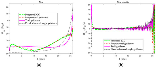
Figure 3.
Attitude cures of the AUV. (a) Yaw. (b) Yaw velocity.
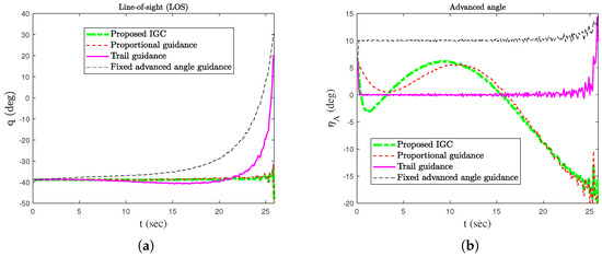
Figure 4.
LOS and advanced angle. (a) LOS. (b) Advanced angle.
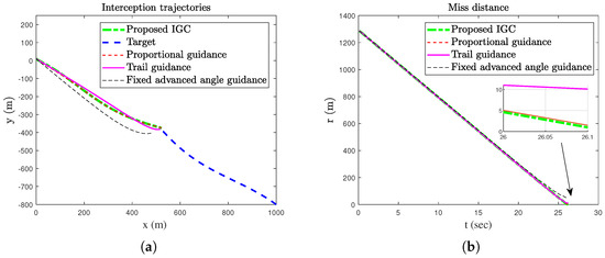
Figure 5.
The trajectories and miss distance of the AUV and the target. (a) Trajectories of the AUV and target. (b) Miss distance.
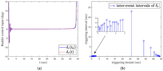
Figure 6.
Event-triggered sliding mode controller. (a) Rudder control input. (b) Inter-event intervals.
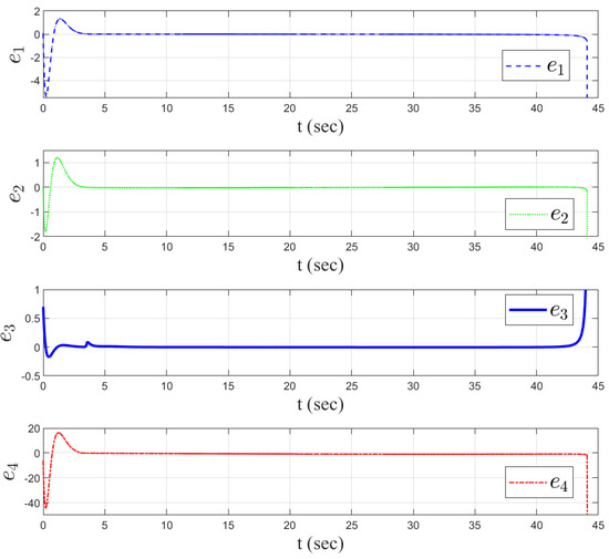
Figure 7.
Estimate errors of the finite-time ESO.

Table 1.
Comparison of miss distance.
5. Conclusions
This paper presents an IGC framework for AUVs intercepting maneuvering targets in complex marine environments with unknown disturbances and unmeasurable states. By leveraging a state transformation method, the proposed scheme converts the original system with unmatched disturbances into a form amenable to effective observer and controller design. A finite-time ESO is developed to estimate the unknown states and disturbances. An event-triggered sliding mode controller is then designed using these estimates, achieving finite-time stability of the closed-loop system while reducing communication and actuator burdens. Simulation results validate the superiority of the proposed method in enhancing interception accuracy and responsiveness compared to traditional approaches, while effectively addressing the challenges of unknown disturbances and unmeasurable states. The designed scheme demonstrates significant potential for practical implementation in AUV interception tasks.
Future work will focus on extending the proposed framework to three-dimensional interception scenarios and incorporating adaptive mechanisms to handle time-varying hydrodynamic parameters. Additionally, experimental validation will be conducted to further verify the practicality of the proposed method.
Author Contributions
Conceptualization, R.W. and J.L.; methodology, R.W. and S.L.; software, R.W., S.L. and Y.L.; validation, R.W., J.L. and S.L.; formal analysis, R.W. and J.L.; investigation, R.W. and S.L.; resources, R.W. and Y.L.; data curation, Y.L. and Y.C.; writing—original draft, R.W. and S.L.; writing—review and editing, J.L., Y.L. and Y.C.; visualization, R.W.; supervision, Y.C.; project administration, R.W.; funding acquisition, R.W., J.L. and Y.L. All authors have read and agreed to the published version of the manuscript.
Funding
This research was funded by the Fundamental Research Funds for the Central Universities under grant 3142024030, the National Key R&D Program of China under grant 2024YFB2908800, the Higher Education Research Project of North China Institute of Science and Technology under grant HKJYZX202405 and the Science and Technology Support Project of Langfang under grant 2024011071.
Institutional Review Board Statement
Not applicable.
Informed Consent Statement
Not applicable.
Data Availability Statement
The data presented in this study are available on request from the corresponding author due to confidentiality regulations.
Acknowledgments
The authors thank the colleagues for their constructive suggestions and research assistance throughout this study.
Conflicts of Interest
The authors declare no conflicts of interest.
References
- Mao, R.; Cui, R.; Yan, W.; Chen, L. Neural Learning-Based Integrated Guidance and Control Algorithm of Multiple Underactuated AUVs. In Proceedings of the 2018 IEEE 8th International Conference on Underwater System Technology: Theory and Applications (USYS), Wuhan, China, 1–3 December 2018; pp. 1–6. [Google Scholar]
- Ye, H.; Zhang, X. A new anti-torpedo torpedo’s guidance law based on variable structure control. In Proceedings of the 2017 3rd IEEE International Conference on Control Science and Systems Engineering (ICCSSE), Beijing, China, 17–19 August 2017; pp. 163–166. [Google Scholar]
- Rong, S.; Wang, H.; Zhang, H. Integrated Guidance and Control Using Prescribed Performance Fractional-order Sliding Mode for Rendezvous of AUV and USV. In Proceedings of the OCEANS 2022, Hampton Roads, Hampton Roads, VA, USA, 17–20 October 2022; pp. 1–8. [Google Scholar]
- Gkesoulis, A.K.; Georgakis, P.; Karras, G.C.; Bechlioulis, C.P. Autonomous Sea Floor Coverage with Constrained Input Autonomous Underwater Vehicles: Integrated Path Planning and Control. Sensors 2025, 25, 1023. [Google Scholar] [CrossRef] [PubMed]
- Cho, D.; Kim, H.J.; Tahk, M.J. Fast adaptive guidance against highly maneuvering targets. IEEE Trans. Aerosp. Electron. Syst. 2016, 52, 671–680. [Google Scholar] [CrossRef]
- Shima, T. Intercept-angle guidance. J. Guid. Control Dyn. 2011, 34, 484–492. [Google Scholar] [CrossRef]
- Zhang, Z.; Li, S.; Luo, S. Terminal guidance laws of missile based on ISMC and NDOB with impact angle constraint. Aerosp. Sci. Technol. 2013, 31, 30–41. [Google Scholar] [CrossRef]
- Guo, J.; Li, Y.; Zhou, J. A new continuous adaptive finite time guidance law against highly maneuvering targets. Aerosp. Sci. Technol. 2019, 85, 40–47. [Google Scholar] [CrossRef]
- Si, C.; Ma, H.; Hao, C.; Yan, S. Robust guidance method with terminal impact angle constraint for autonomous underwater vehicle. Acta Acust. 2018, 53, 342–347. [Google Scholar]
- Gong, M.; Zhou, D.; Zou, X. Saturated super-twisting sliding mode missile guidance. Chin. J. Aeronaut. 2022, 35, 292–300. [Google Scholar]
- Fan, Y.; Liu, B.; Wang, G.; Mu, D. Adaptive fast non-singular terminal sliding mode path following control for an underactuated unmanned surface vehicle with uncertainties and unknown disturbances. Sensors 2021, 21, 7454. [Google Scholar] [CrossRef]
- Zhang, D.; Ma, P.; Wang, S.; Chao, T. Multi-constraints adaptive finite-time integrated guidance and control design. Aerosp. Sci. Technol. 2020, 107, 106334. [Google Scholar] [CrossRef]
- Lv, P.; Lv, J.; Hong, Z.; Xu, L. An Integrated Navigation Method Aided by Position Correction Model and Velocity Model for AUVs. Sensors 2024, 24, 5396. [Google Scholar] [CrossRef]
- Wei, S.; Song, S. Integral barrier Lyapunov function-based fixed-time integrated guidance and control with asymmetric field-of-view angle constraints. ISA Transactions 2024, 151, 183–197. [Google Scholar] [CrossRef] [PubMed]
- Williams, D.; Richman, J.; Friedland, B. Design of an integrated strapdown guidance and control system for a tactical missile. In Proceedings of the Guidance and Control Conference, Gatlinburg, TN, USA, 15–17 August 1983; p. 2169. [Google Scholar]
- Zhang, Z.; Li, S.; Luo, S. Composite guidance laws based on sliding mode control with impact angle constraint and autopilot lag. Trans. Inst. Meas. Control 2013, 35, 764–776. [Google Scholar] [CrossRef]
- Sharma, M.; Richards, N. Adaptive, integrated guidance and control for missile interceptors. In Proceedings of the AIAA Guidance, Navigation, and Control Conference and Exhibit, Providence, RI, USA, 16–19 August 2004; p. 4880. [Google Scholar]
- He, S.; Wang, W.; Wang, J. Three-dimensional multivariable integrated guidance and control design for maneuvering targets interception. J. Frankl. Inst. 2016, 353, 4330–4350. [Google Scholar] [CrossRef]
- Yuan, J.; Chai, Z.; Chen, Q.; Dong, Z.; Wan, L. ESO-Based Non-Singular Terminal Filtered Integral Sliding Mode Backstepping Control for Unmanned Surface Vessels. Sensors 2025, 25, 351. [Google Scholar] [CrossRef] [PubMed]
- Lu, J.; Wei, Q.; Wang, F.Y. Parallel control for optimal tracking via adaptive dynamic programming. IEEE/CAA J. Autom. Sin. 2020, 7, 1662–1674. [Google Scholar] [CrossRef]
- Lu, J.; Wei, Q.; Wang, F.Y. Parallel Control for Nonzero-Sum Games With Completely Unknown Nonlinear Dynamics via Reinforcement Learning. IEEE Trans. Syst. Man, Cybern. Syst. 2025, 55, 2884–2896. [Google Scholar] [CrossRef]
- Wang, S.; Wang, W.; Xiong, S. Impact angle constrained three-dimensional integrated guidance and control for STT missile in the presence of input saturation. ISA Trans. 2016, 64, 151–160. [Google Scholar] [CrossRef]
- Jia, Y.; Song, B.; Zhao, X. Rocket Assists Acoustic Jammer Counterwork Wired Guidance Torpedo Models. In Proceedings of the 2008 7th World Congress on Intelligent Control and Automation, Chongqing, China, 25–27 June 2008; pp. 6301–6304. [Google Scholar]
- Pei, P.; Ji, Y.; He, S.; Wang, J.; Lin, D. Integrated guidance and control using adaptive backstepping approach for maneuvering target interception. IFAC-PapersOnLine 2020, 53, 9458–9464. [Google Scholar] [CrossRef]
- Li, G.; Wu, Y.; Liu, J.; Zhao, J. Nonlinear transformed function-based adaptive finite-time integrated guidance and control design with full state constraints. Aerosp. Sci. Technol. 2023, 143, 108723. [Google Scholar] [CrossRef]
- Liang, X.; Xu, B.; Jia, K.; Liu, X. Adaptive NN control of integrated guidance and control systems based on disturbance observer. J. Frankl. Inst. 2023, 360, 65–86. [Google Scholar] [CrossRef]
- Yang, L.; Li, Y. Integrated Guidance and Control Design Subject to Actuator Saturation Based on Fully Actuated System Approach. In Proceedings of the 2024 3rd Conference on Fully Actuated System Theory and Applications (FASTA), Shenzhen, China, 10–12 May 2024; pp. 998–1003. [Google Scholar]
- Awad, A.; Wang, H. Roll-pitch-yaw autopilot design for nonlinear time-varying missile using partial state observer based global fast terminal sliding mode control. Chin. J. Aeronaut. 2016, 29, 1302–1312. [Google Scholar] [CrossRef]
- Wu, Y.; He, X.; Shi, L.; Dong, S. Multi-Observer Fusion Based Minimal-Sensor Adaptive Control for Ship Dynamic Positioning Systems. Sensors 2025, 25, 679. [Google Scholar] [CrossRef] [PubMed]
- Yao, C.; Liu, Z.; Zhou, H.; Gao, C.; Li, J.; Zhang, Z. Integrated guidance and control for underactuated fixed-trim moving mass flight vehicles. Aerosp. Sci. Technol. 2023, 142, 108680. [Google Scholar] [CrossRef]
- Zhao, J.; Zhang, Y.; Li, S.; Wang, J.; Fang, L.; Ning, L.; Feng, J.; Zhang, J. An Improved Unscented Kalman Filter Applied to Positioning and Navigation of Autonomous Underwater Vehicles. Sensors 2025, 25, 551. [Google Scholar] [CrossRef]
- Wang, Q.; Ran, M.; Dong, C. Robust partial integrated guidance and control for missiles via extended state observer. ISA Trans. 2016, 65, 27–36. [Google Scholar] [CrossRef]
- Gu, N.; Wang, D.; Peng, Z.; Wang, J.; Han, Q.L. Disturbance observers and extended state observers for marine vehicles: A survey. Control Eng. Pract. 2022, 123, 105158. [Google Scholar] [CrossRef]
- Wu, G.X.; Ding, Y.; Tahsin, T.; Atilla, I. Adaptive neural network and extended state observer-based non-singular terminal sliding modetracking control for an underactuated USV with unknown uncertainties. Appl. Ocean. Res. 2023, 135, 103560. [Google Scholar] [CrossRef]
- Zhang, X.; Xu, T.; Zhang, Z.; Duan, Z. Parallel extended state observer based control for uncertain nonlinear systems. Neurocomputing 2023, 557, 126687. [Google Scholar] [CrossRef]
- Lu, J.; Wei, Q.; Zhou, T.; Wang, Z.; Wang, F.Y. Event-triggered near-optimal control for unknown discrete-time nonlinear systems using parallel control. IEEE Trans. Cybern. 2023, 53, 1890–1904. [Google Scholar] [CrossRef]
- Lu, J.; Han, L.; Wei, Q.; Wang, X.; Dai, X.; Wang, F.Y. Event-triggered deep reinforcement learning using parallel control: A case study in autonomous driving. IEEE Trans. Intell. Veh. 2023, 8, 2821–2831. [Google Scholar] [CrossRef]
- Yang, H.; Wang, D.; Lyu, R. An Optimal Head-on Guidance Law for Integrated Guidance and Control of Underwater Interceptor. J. Unmanned Undersea Syst. 2018, 26, 228–246. [Google Scholar]
- Xu, D.; Wu, X.; Ren, Z. Torpedo Automatic Control System; Northwestern Polytechnical University Press: Xi’an, China, 2001; pp. 319–320. [Google Scholar]
- Gao, Y.; Huang, W.; Lin, C. Torpedo Navigation and Control Technology; The Publishing House of Ordnance Industry: Beijing, China, 2015; pp. 150–152. [Google Scholar]
- Bhat, S.P.; Bernstein, D.S. Finite-time stability of continuous autonomous systems. SIAM J. Control Optim. 2000, 38, 751–766. [Google Scholar] [CrossRef]
- Rao, S.; Ghose, D. Terminal impact angle constrained guidance laws using variable structure systems theory. IEEE Trans. Control. Syst. Technol. 2013, 21, 2350–2359. [Google Scholar] [CrossRef]
- Yu, S.; Yu, X.; Shirinzadeh, B.; Man, Z. Continuous finite-time control for robotic manipulators with terminal sliding mode. Automatica 2005, 41, 1957–1964. [Google Scholar] [CrossRef]
- Yu, J.; Shi, P.; Zhao, L. Finite-time command filtered backstepping control for a class of nonlinear systems. Automatica 2018, 92, 173–180. [Google Scholar] [CrossRef]
- Hermes, H. Homogeneous coordinates and continuous asymptotically stabilizing feedback control. Differ. Equ. Stab. Control 1991, 249. [Google Scholar]
- Rosier, L. Homogeneous Lyapunov function for homogeneous continuous vector field. Syst. Control Lett. 1992, 19, 467–473. [Google Scholar] [CrossRef]
- Bhat, S.P.; Bernstein, D.S. Finite-time stability of homogeneous systems. In Proceedings of the 1997 American Control Conference (Cat. No. 97CH36041), Albuquerque, NM, USA, 6 June 1997; Volume 4, pp. 2513–2514. [Google Scholar]
- Bhat, S.; Bernstein, D.S. Geometric homogeneity with applications to finite-time stability. Math. Control Signals Syst. 2005, 17, 101–127. [Google Scholar] [CrossRef]
- Sastry, S. Nonlinear Systems: Analysis, Stability, and Control; Springer Science & Business Media: New York, NY, USA, 2013; Volume 10. [Google Scholar]
- Li, M.; Guo, C.; Yu, H.; Yuan, Y. Event-triggered containment control of networked underactuated unmanned surface vehicles with finite-time convergence. Ocean Eng. 2022, 246, 110548. [Google Scholar] [CrossRef]
- Abramowitz, M.; Stegun, I.A. Handbook of Mathematical Functions with Formulas, Graphs, and Mathematical Tables; US Government Printing Office: Washington, DC, USA, 1968; Volume 55. [Google Scholar]
- Yang, L.; Yang, J. Nonsingular fast terminal sliding-mode control for nonlinear dynamical systems. Int. J. Robust Nonlinear Control 2011, 21, 1865–1879. [Google Scholar] [CrossRef]
- Shen, Y.; Huang, Y. Uniformly observable and globally Lipschitzian nonlinear systems admit global finite-time observers. IEEE Trans. Autom. Control 2009, 54, 2621–2625. [Google Scholar] [CrossRef]
- Shao, X.; Wang, H. Back-stepping active disturbance rejection control design for integrated missile guidance and control system via reduced-order ESO. ISA Trans. 2015, 57, 10–22. [Google Scholar] [CrossRef]
- Haskara, I. On sliding mode observers via equivalent control approach. Int. J. Control 1998, 71, 1051–1067. [Google Scholar] [CrossRef]
- Sun, G.; Ren, X.; Chen, Q.; Li, D. A modified dynamic surface approach for control of nonlinear systems with unknown input dead zone. Int. J. Robust Nonlinear Control 2015, 25, 1145–1167. [Google Scholar] [CrossRef]
- Xing, L.; Wen, C.; Liu, Z.; Su, H.; Cai, J. Event-Triggered Adaptive Control for a Class of Uncertain Nonlinear Systems. IEEE Trans. Autom. Control 2017, 62, 2071–2076. [Google Scholar] [CrossRef]
Disclaimer/Publisher’s Note: The statements, opinions and data contained in all publications are solely those of the individual author(s) and contributor(s) and not of MDPI and/or the editor(s). MDPI and/or the editor(s) disclaim responsibility for any injury to people or property resulting from any ideas, methods, instructions or products referred to in the content. |
© 2025 by the authors. Licensee MDPI, Basel, Switzerland. This article is an open access article distributed under the terms and conditions of the Creative Commons Attribution (CC BY) license (https://creativecommons.org/licenses/by/4.0/).