


Highly Selective Tilted Triangular Springs with Constant Force Reaction †


Abstract
1. Introduction
2. Materials and Methods
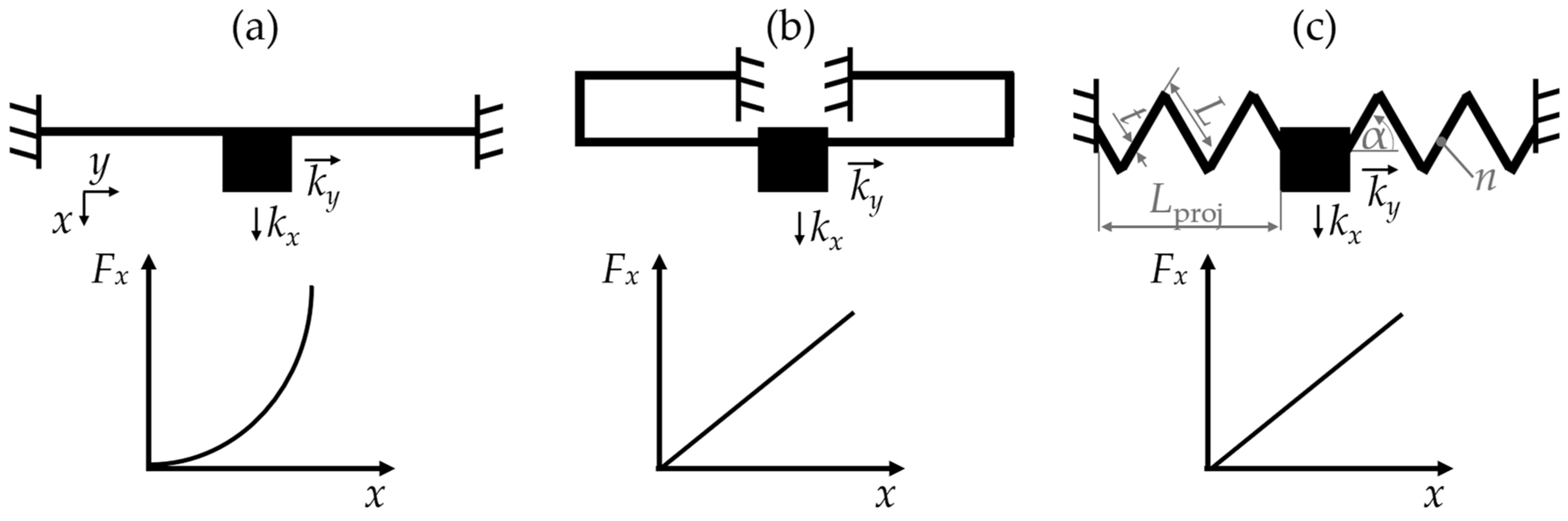
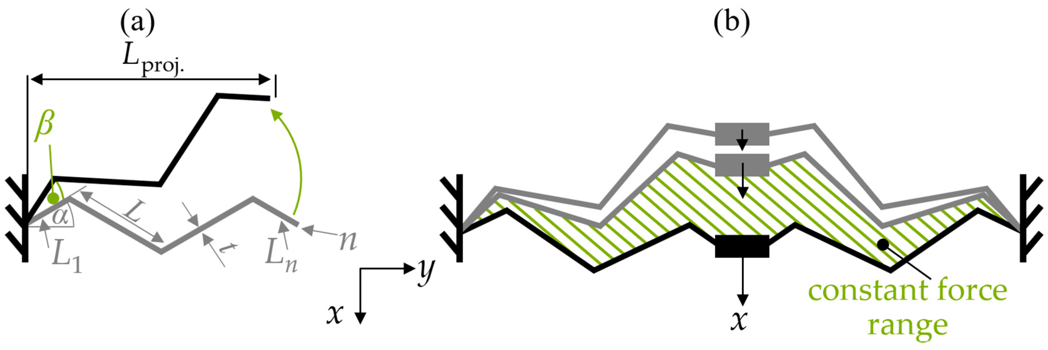
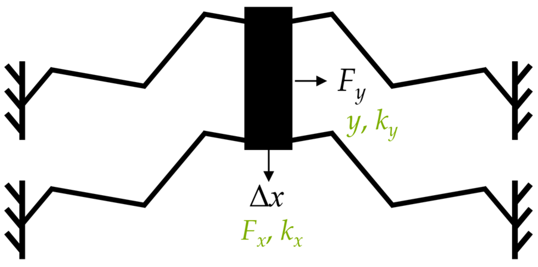
2.1. Spring Design
2.2. Simulation Procedure
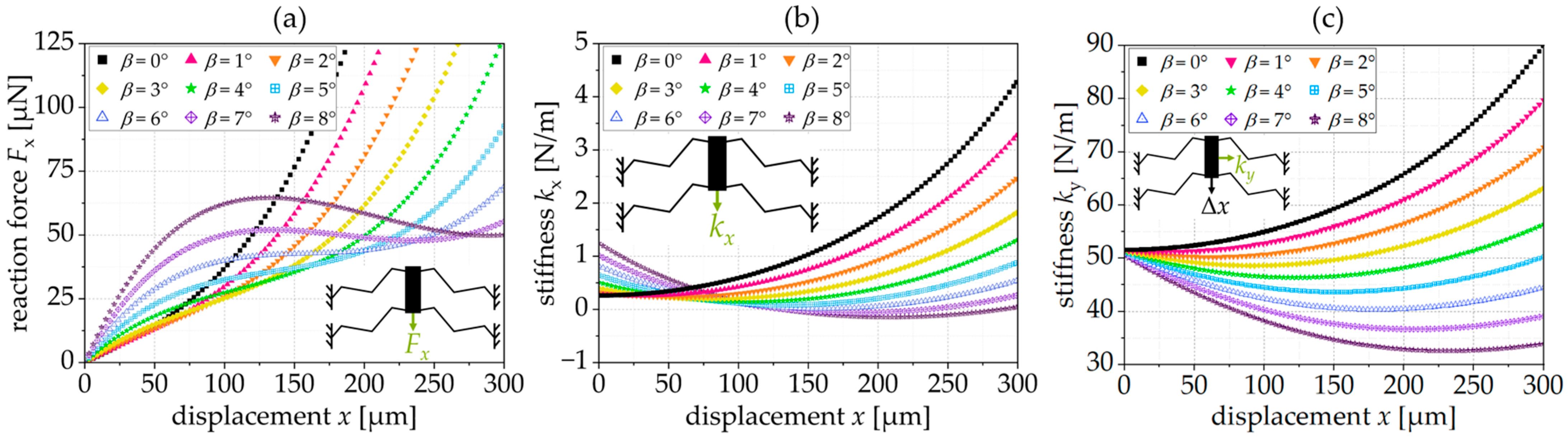
2.3. Simulation Results
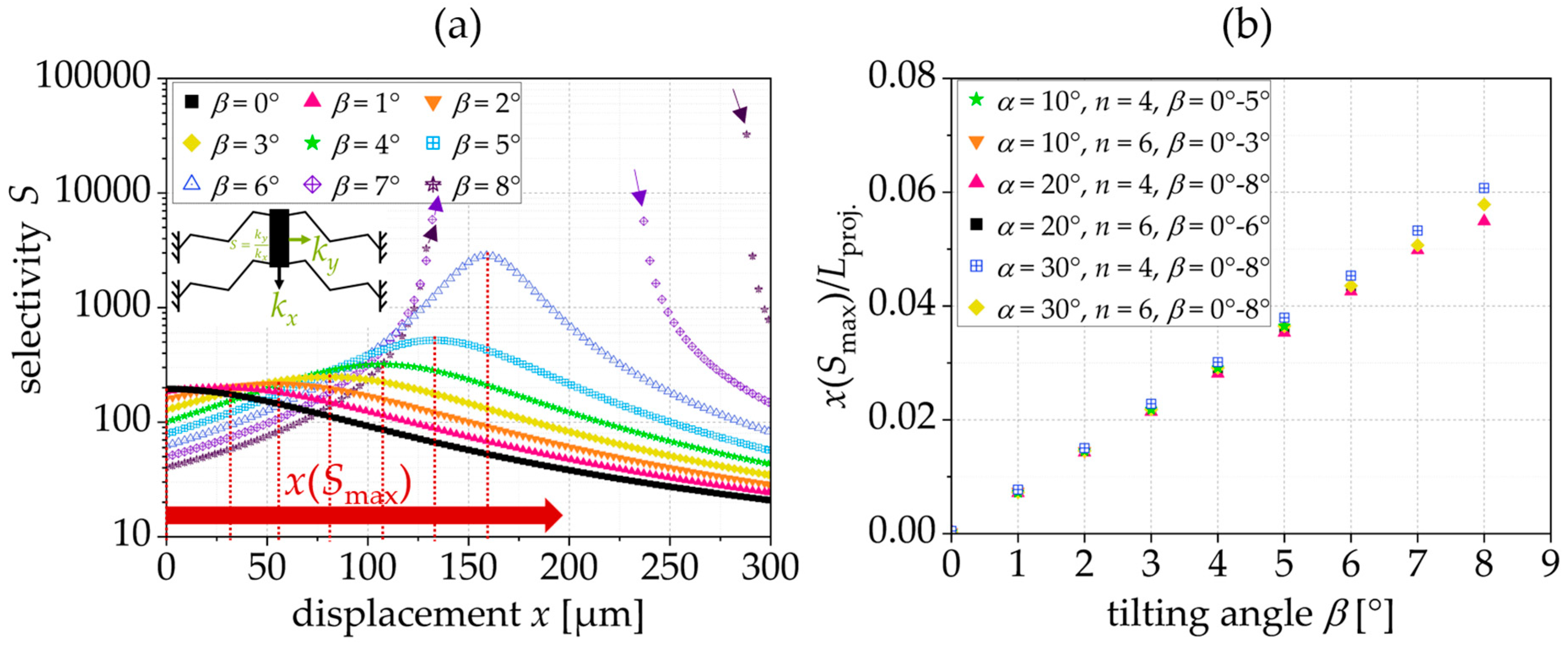
2.3.1. Constant Force Range (CFR) and Selectivity


2.3.2. Influence of the Spring Parameter on the Constant Force Range

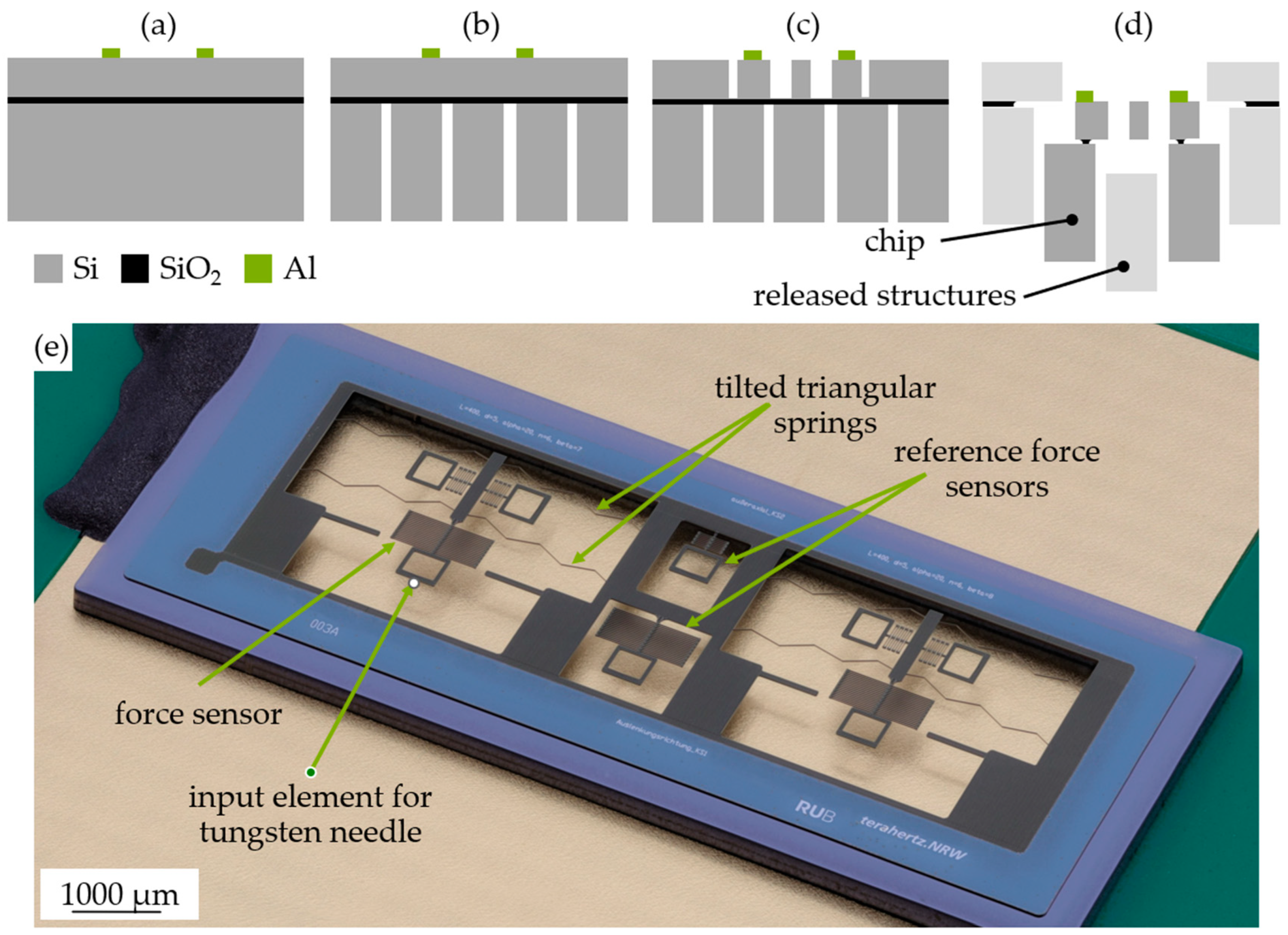
2.4. Fabrication
2.5. Experimental Charcterization Procedure
3. Experimental Results and Discussion
3.1. Overview of the Results
3.2. Characterization of the Tilted Triangular Springs
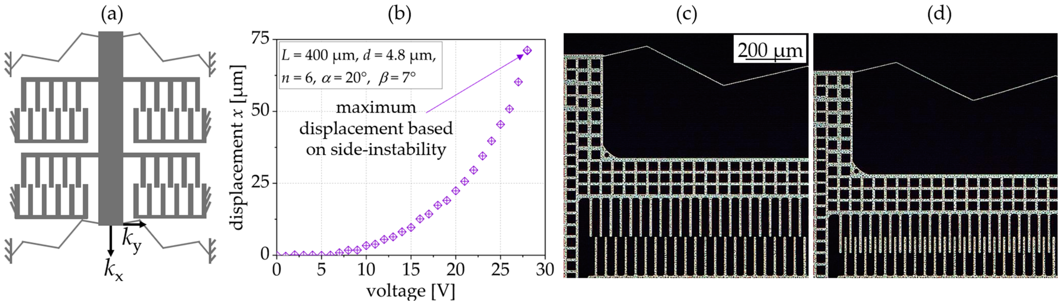
4. Application in Comb Drive Actuators
5. Conclusions
Author Contributions
Funding
Institutional Review Board Statement
Informed Consent Statement
Data Availability Statement
Acknowledgments
Conflicts of Interest
References
- Legtenberg, R.; Groeneveld, A.W.; Elwenspoek, M. Comb-drive actuators for large displacements. J. Micromech. Microeng. 1996, 6, 320. [Google Scholar] [CrossRef]
- Schmitt, P.; Schmitt, L.; Tsivin, N.; Hoffmann, M. Highly Selective Guiding Springs for Large Displacements in Surface MEMS. J. Microelectromech. Syst. 2021, 30, 597–611. [Google Scholar] [CrossRef]
- Schomburg, W.K. Introduction to Microsystem Design; Springer: Berlin, Germany, 2011. [Google Scholar]
- Gao, Y.; You, Z.; Zhao, J. lectrostatic comb-drive actuator for MEMS relays/switches with double-tilt comb fingers and tilted parallelogram beams. J. Micromech. Microeng. 2015, 25, 45003. [Google Scholar] [CrossRef]
- Schmitt, L.; Conrad, P.; Kopp, A.; Ament, C.; Hoffmann, M. Non-Inchworm Electrostatic Cooperative Micro-Stepper-Actuator Systems with Long Stroke. Actuators 2023, 12, 150. [Google Scholar] [CrossRef]
- Leadenham, S.; Erturk, A. M-shaped asymmetric nonlinear oscillator for broadband vibration energy harvesting: Harmonic balance analysis and experimental validation. J. Sound Vib. 2014, 333, 6209–6223. [Google Scholar] [CrossRef]
- IMorkvenaite-Vilkonciene; Bucinskas, V.; Subaciute-Zemaitiene, J.; Sutinys, E.; Virzonis, D.; Dzedzickis, A. Development of Electrostatic Microactuators: 5-Year Progress in Modeling, Design, and Applications. Micromachines 2022, 13, 1256. [Google Scholar] [CrossRef] [PubMed]
- Wang, P.; Xu, Q. Design and modeling of constant-force mechanisms: A survey. Mech. Mach. Theory 2018, 119, 1–21. [Google Scholar] [CrossRef]
- Yang, S.; Xu, Q. Design and simulation of a passive-type constant-force MEMS microgripper. In Proceedings of the 2017 IEEE International Conference on Robotics and Biomimetics (ROBIO), Macau, Macao, 5–8 December 2017; pp. 1100–1105. [Google Scholar]
- Ma, C.; Du, J.; Liu, Y.; Chu, Y. Overview of micro-force sensing methods. Appl. Mech. Mater. 2014, 462–463, 25–31. [Google Scholar] [CrossRef]
- Thewes, A.C.; Schmitt, P.; Löhler, P.; Hoffmann, M. Design and characterization of an electrostatic constant-force actuator based on a non-linear spring system. Actuators 2021, 10, 192. [Google Scholar] [CrossRef]
- Li, B.; Li, G.; Lin, W.; Xu, P. Design and constant force control of a parallel polishing machine. In Proceedings of the 2014 4th IEEE International Conference on Information Science and Technology, Shenzhen, China, 26–28 April 2014; pp. 324–328. [Google Scholar]
- Erlbacher, E. Method for Applying Constant Force with Nonlinear Feedback Control and Constant Force Device Using Same. U.S. Patent 5,448,146, 5 September 1995. [Google Scholar]
- Boudaoud, M.; Haddab, Y.; Le Gor, Y. Modeling and optimal force control of a nonlinear electrostatic microgripper. IEEE/ASME Trans. Mechatron. 2012, 18, 1130–1139. [Google Scholar] [CrossRef]
- Shahan, D.; Fulcher, B.; Seepersad, C.C. Robust design of negative stiffness elements fabricated by selective laser sintering. In Proceedings of the 2011 International Solid Freeform Fabrication Symposium, Austin, TX, USA, 11–14 August 2024; University of Texas at Austin: Austin, TX, USA, 2011. [Google Scholar]
- Qiu, J.; Lang, J.H.; Slocum, A.H. A curved-beam bistable mechanism. J. Microelectromech. Syst. 2004, 13, 137–146. [Google Scholar] [CrossRef]
- Qiu, J.; Lang, J.H.; Slocum, A.H. A centrally-clamped parallel-beam bistable MEMS mechanism. Technical Digest. In Proceedings of the MEMS 2001. 14th IEEE International Conference on Micro Electro Mechanical Systems (MEMS), Interlaken, Switzerland, 25 January 2001; pp. 353–356. [Google Scholar]
- Vysotskyi, B.; Parrain, F.; Aubry, D.; Gaucher, P.; Le Roux, X.; Lefeuvre, E. Engineering the structural nonlinearity using multimodal-shaped springs in MEMS. J. Microelectromech. Syst. 2018, 27, 40–46. [Google Scholar] [CrossRef]
- Vysotskyi, B.; Parrain, F.; Aubry, D.; Gaucher, P.; Lefeuvre, E. Innovative energy harvester design using bistable mechanism with compensational springs in gravity field. Proc. J. Phys. Conf. 2016, 773, 12064. [Google Scholar] [CrossRef]
- Sari, I.; Zeimpekis, I.; Kraft, M. A dicing free SOI process for MEMS devices. Microelectron. Eng. 2012, 95, 121–129. [Google Scholar] [CrossRef]


| Analyzed in | β | α | n | L | t | d | Analysis of |
|---|---|---|---|---|---|---|---|
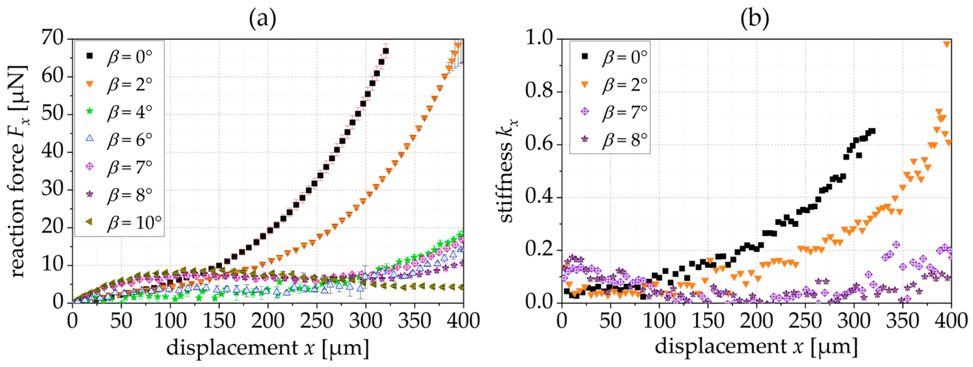
| Figure 4a–c | 0–8° | 20° | 6 | 400 µm | 5 µm | 20 µm | reaction force Fx, stiffness kx and ky |
| Figure 5a | 0–8° | 20° | 6 | 400 µm | 5 µm | 20 µm | selectivity S |
| Figure 5b | 0°–8° | 10°, 20°, 30° | 4, 6 | 400 µm | 5 µm | 20 µm | correlation Smax., Lproj. and β |
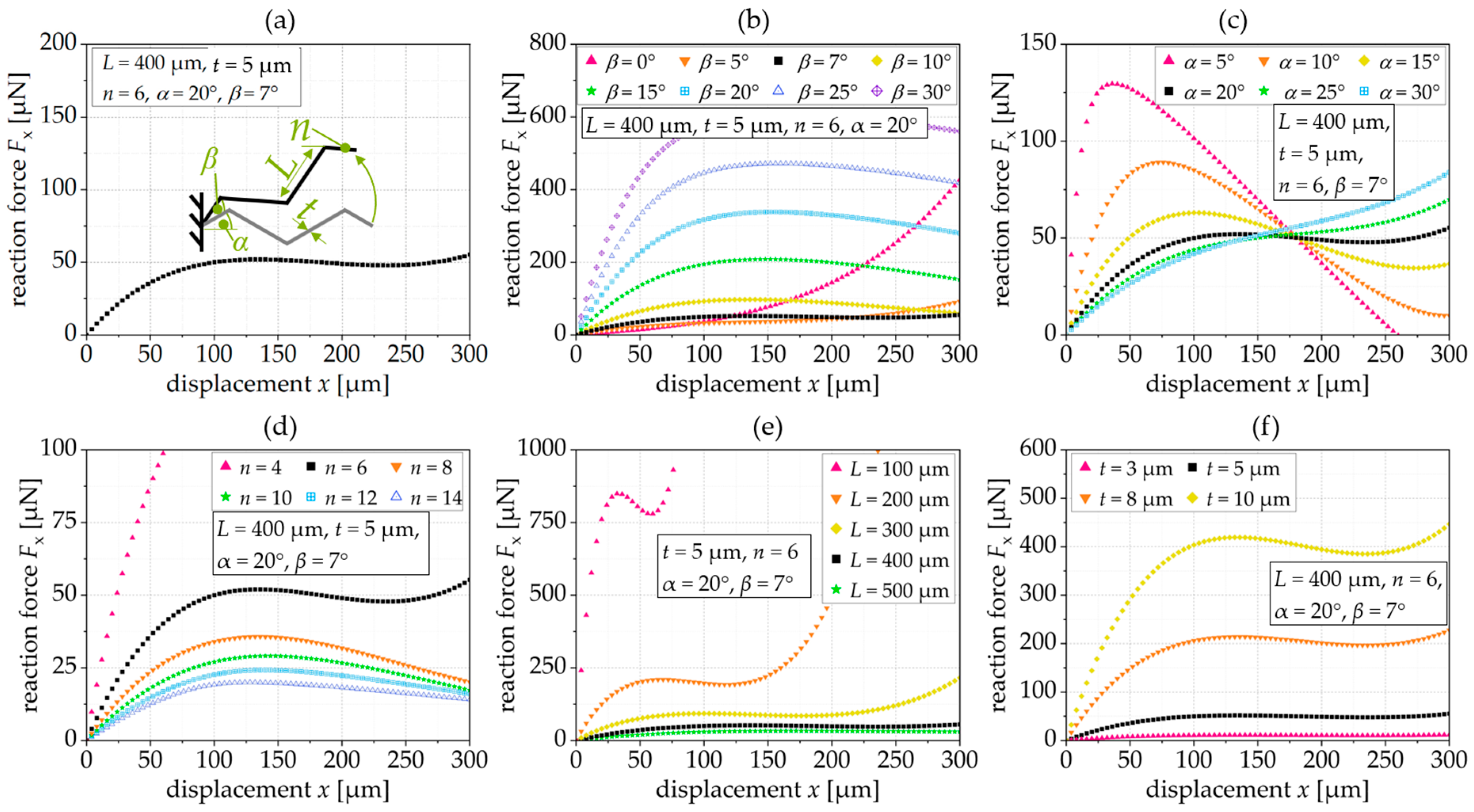
| Figure 6a standard spring | 7° | 20° | 6 | 400 µm | 5 µm | 20 µm | constant force |
| Figure 6b | 0–30° | 20° | 6 | 400 µm | 5 µm | 20 µm | Influence of β |
| Figure 6c | 7° | 5–30° | 6 | 400 µm | 5 µm | 20 µm | Influence of α |
| Figure 6d | 7° | 20° | 4–14 | 400 µm | 5 µm | 20 µm | Influence of n |
| Figure 6e | 7° | 20° | 6 | 100…500 µm | 5 µm | 20 µm | Influence of L |
| Figure 6f | 7° | 20° | 6 | 400 µm | 3…10 µm | 20 µm | Influence of t |
| Analyzed in | β [°] | α [°] | n | L [µm] | t [µm] | d [µm] | Fx,konst. (exp.) | Fkonst., range (exp.) |
|---|---|---|---|---|---|---|---|---|
| Figure 9 | 0, 2, 4, 6, 7, 8, 10 | 20 | 6 | 400 | 4.8 | 20 | 6.8 ± 0.3 µN (β = 7°) | 97…267 µm (β = 7°) |
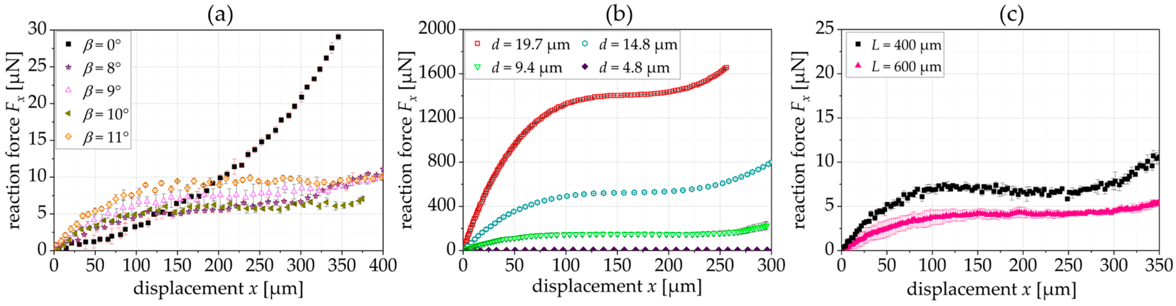
| Figure 10a | 0, 8, 9, 10, 11 | 30 | 6 | 400 | 4.8 | 20 | 6.4 ± 1.1 µN (β = 10°) | 105…355 µm (β = 10°) |
| Figure 10b | 7 | 20 | 6 | 400 | 4.8, 9.4, 14.8, 19.7 | 20 | 147.4 ± 1.1 µN (t = 9.4 µm) | 103…228 µm (t = 9.4 µm) |
| Figure 10c | 7 | 20 | 6 | 400, 600 | 4.8 | 20 | 4.1 ± 0.3 µN (L = 600 µm) | 74…324 µm (L = 600 µm) |
Disclaimer/Publisher’s Note: The statements, opinions and data contained in all publications are solely those of the individual author(s) and contributor(s) and not of MDPI and/or the editor(s). MDPI and/or the editor(s) disclaim responsibility for any injury to people or property resulting from any ideas, methods, instructions or products referred to in the content. |
© 2024 by the authors. Licensee MDPI, Basel, Switzerland. This article is an open access article distributed under the terms and conditions of the Creative Commons Attribution (CC BY) license (https://creativecommons.org/licenses/by/4.0/).
Share and Cite
Schmitt, L.; Schmitt, P.; Hoffmann, M. Highly Selective Tilted Triangular Springs with Constant Force Reaction. Sensors 2024, 24, 1677. https://doi.org/10.3390/s24051677
Schmitt L, Schmitt P, Hoffmann M. Highly Selective Tilted Triangular Springs with Constant Force Reaction. Sensors. 2024; 24(5):1677. https://doi.org/10.3390/s24051677
Chicago/Turabian StyleSchmitt, Lisa, Philip Schmitt, and Martin Hoffmann. 2024. "Highly Selective Tilted Triangular Springs with Constant Force Reaction" Sensors 24, no. 5: 1677. https://doi.org/10.3390/s24051677
APA StyleSchmitt, L., Schmitt, P., & Hoffmann, M. (2024). Highly Selective Tilted Triangular Springs with Constant Force Reaction. Sensors, 24(5), 1677. https://doi.org/10.3390/s24051677