

An Effective GNSS/PDR Fusion Positioning Algorithm on Smartphones for Challenging Scenarios
Abstract
1. Introduction
2. PDR Algorithm
2.1. Principles of PDR
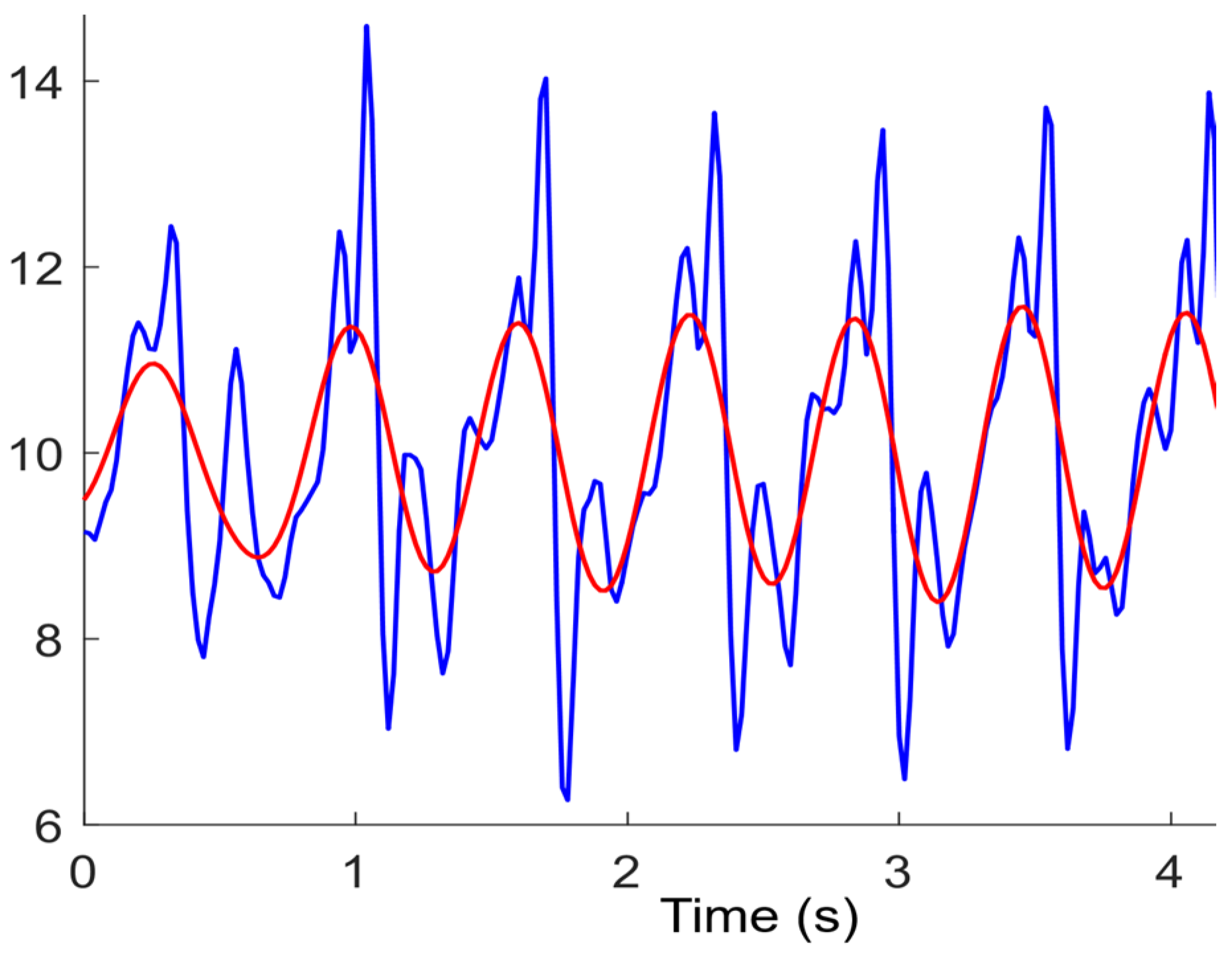
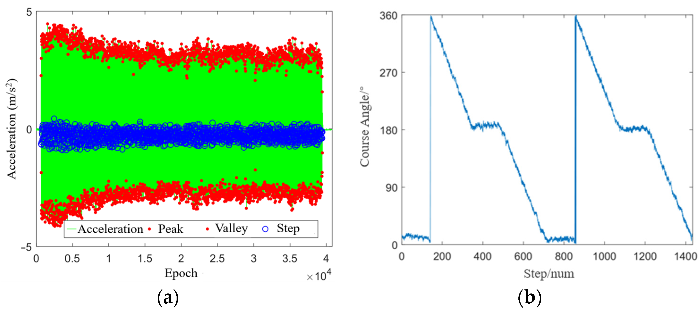
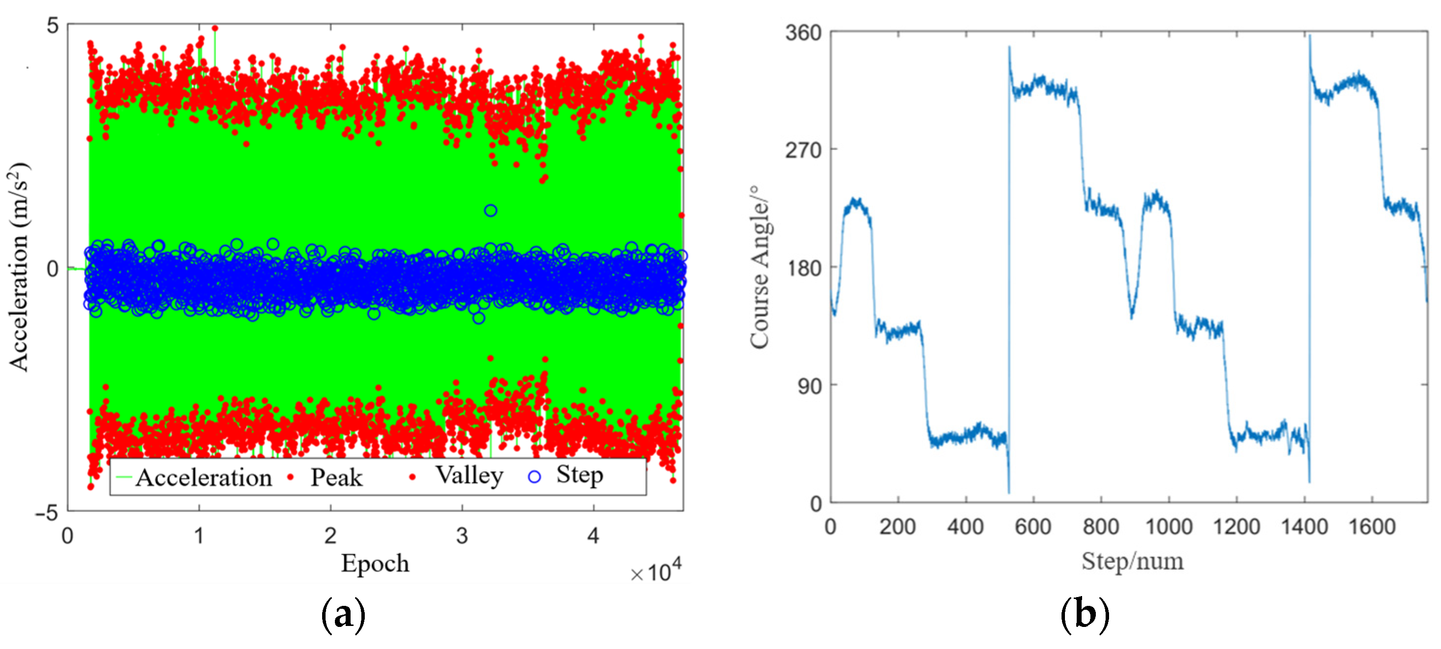
2.2. Step Detection
2.3. Step Length Estimation
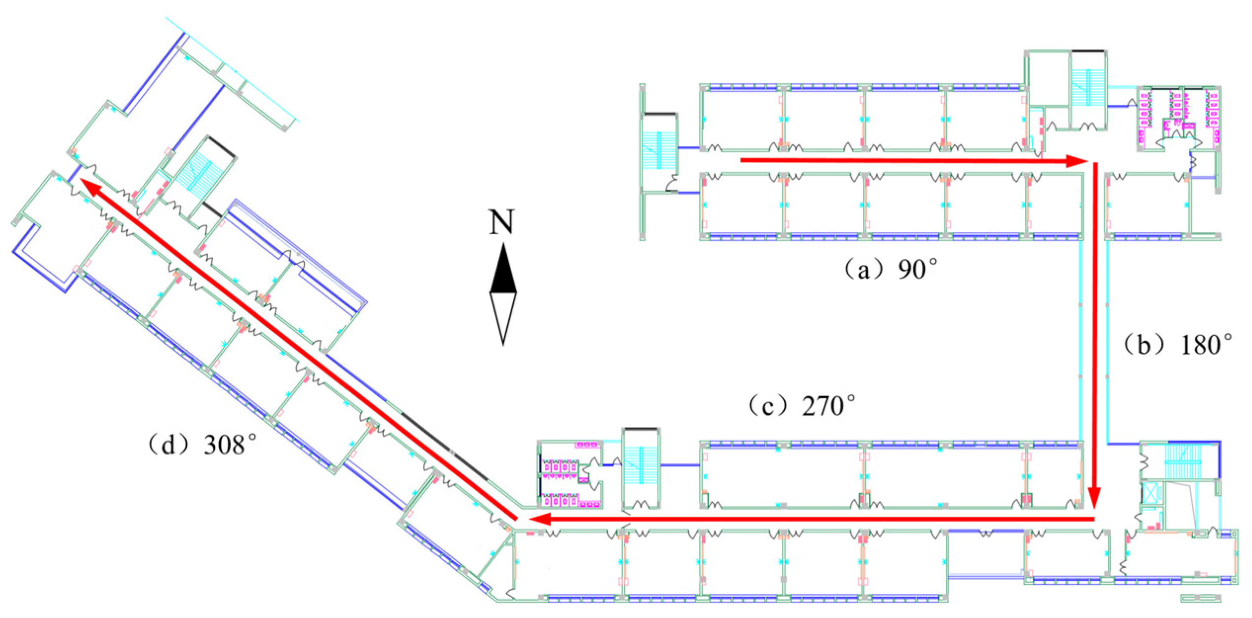
2.4. Heading Estimation
3. GNSS/PDR Fusion Positioning
3.1. GNSS/PDR Fusion Positioning Algorithm
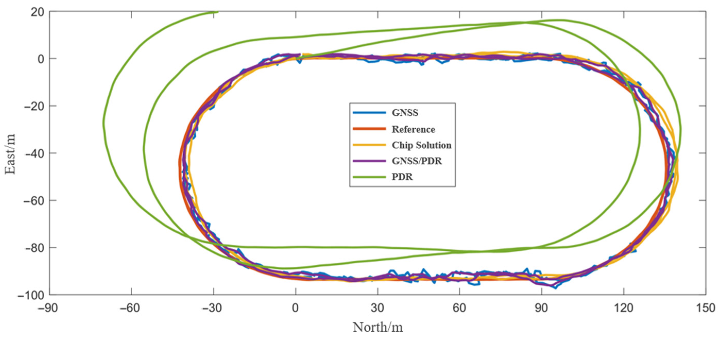
3.2. Positioning Performance in the Open Scenario
3.3. Positioning Performance in the Semiopen Scenario
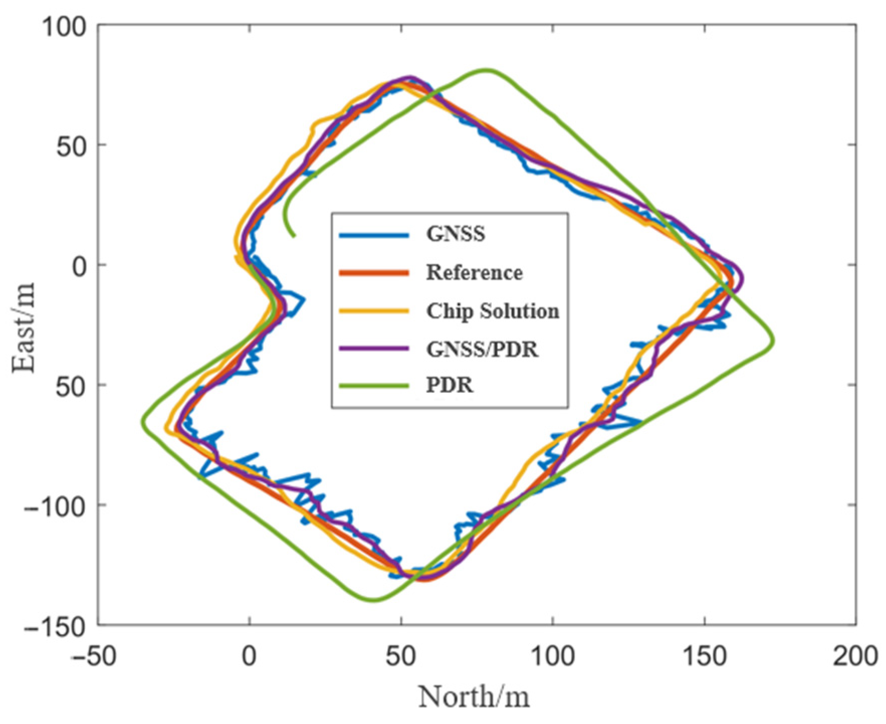
3.4. Positioning Performance under the Blocked Scenario
4. Development and Performance Analysis of the Real-Time Fusion Positioning Software
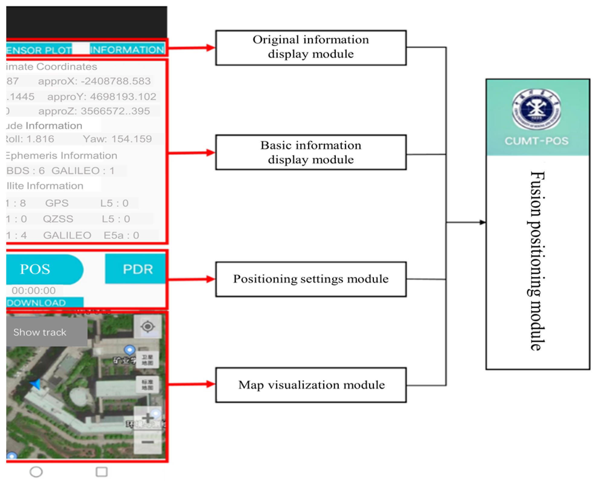
4.1. Design Framework and Functions
- (1)
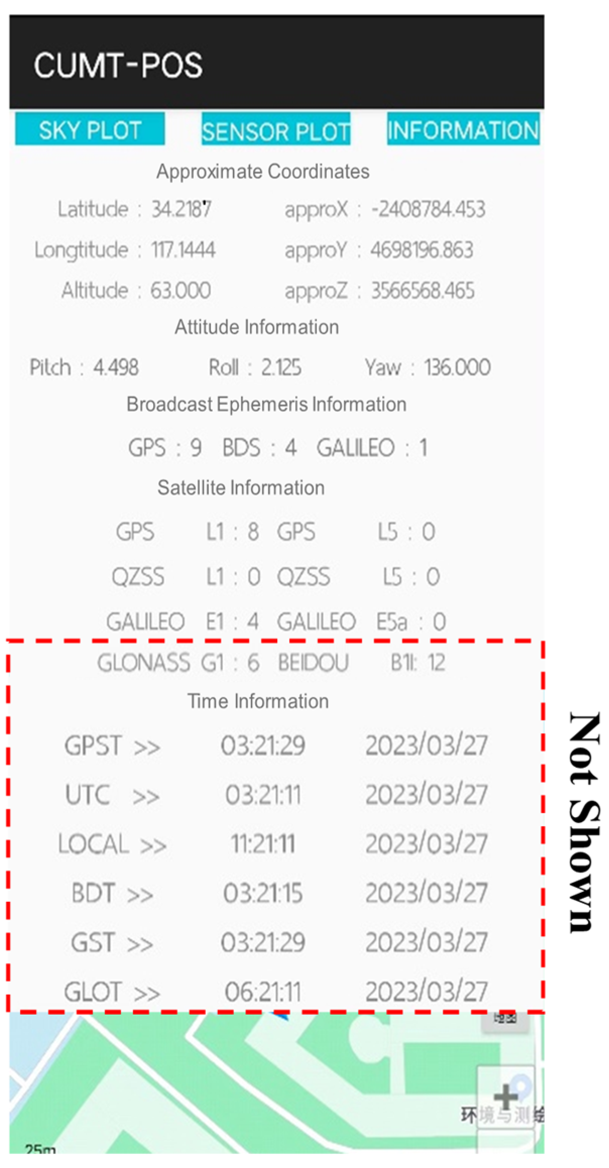
- Original information display module
- (2)
- Basic information display module
- (3)
- Map visualization module
- (4)
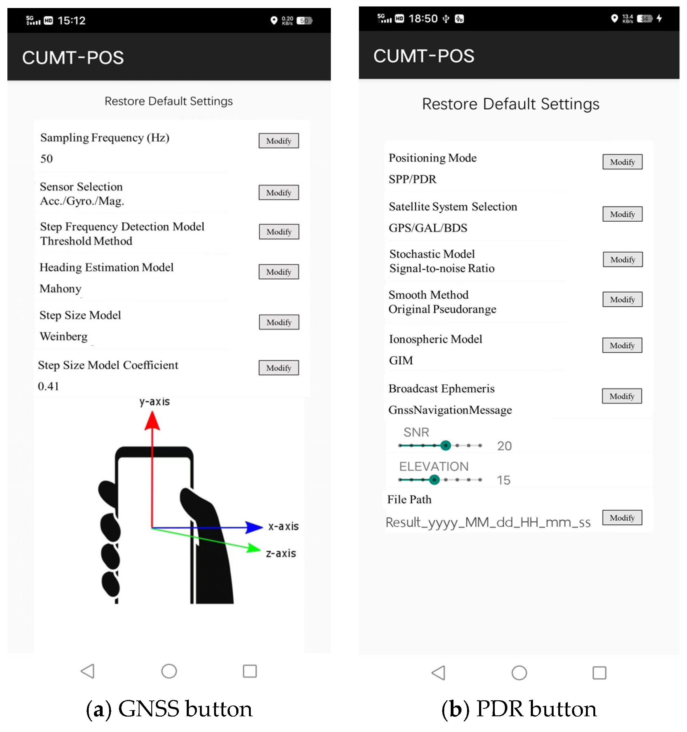
- Positioning setting module
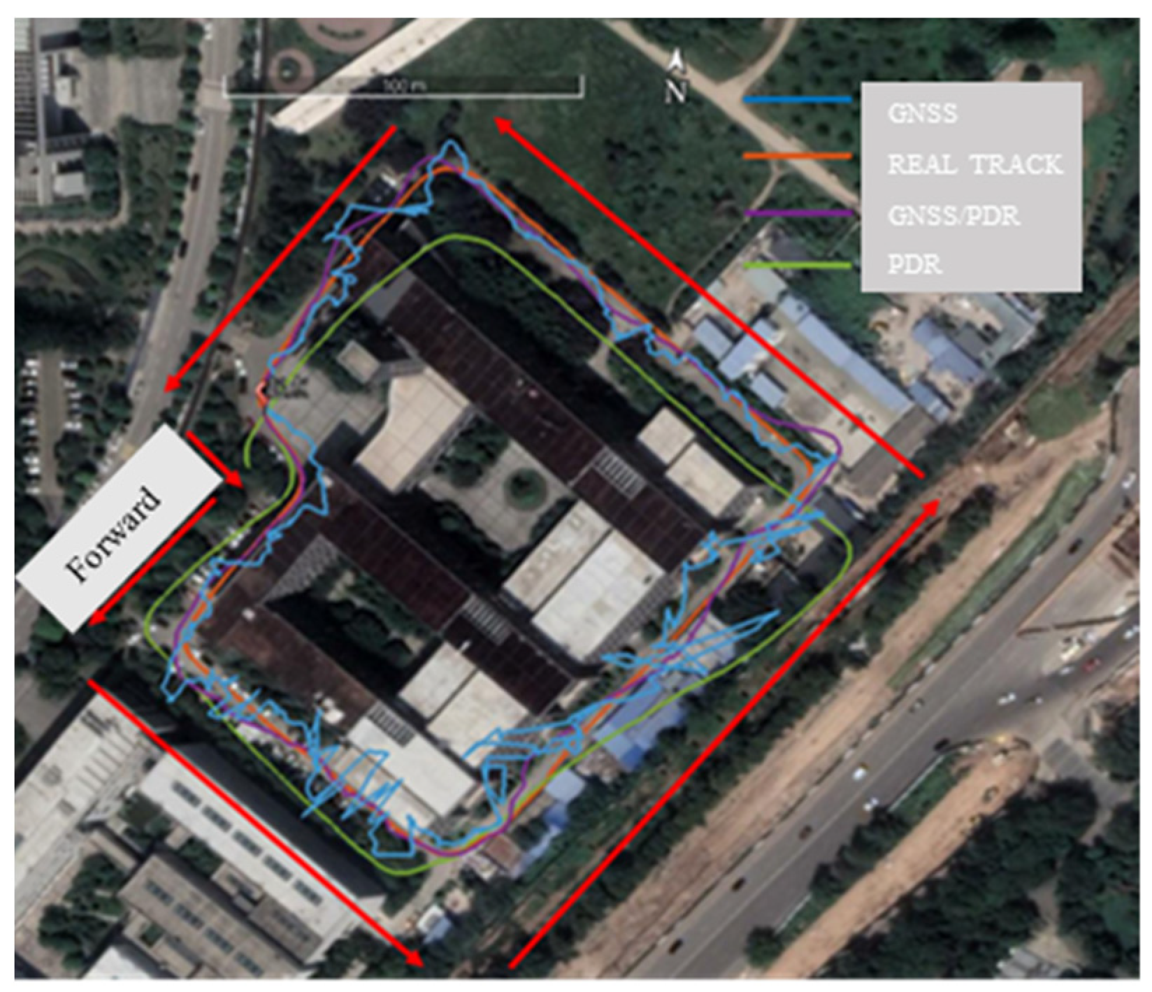
4.2. GNSS/PDR Real-Time Positioning Software Performance Analysis
5. Conclusions
Author Contributions
Funding
Informed Consent Statement
Data Availability Statement
Conflicts of Interest
References
- Montenbruck, O.; Steigenberger, P.; Prange, L.; Deng, Z.; Zhao, Q.; Perosanz, F.; Romero, I.; Noll, C.; Stuerze, A.; Weber, G.; et al. The Multi-GNSS Experiment (MGEX) of the International GNSS Service (IGS)—Achievements, prospects and challenges. Adv. Space Res. 2017, 59, 1671–1697. [Google Scholar] [CrossRef]
- Li, X.; Zhang, X.; Ren, X.; Fritsche, M.; Wickert, J.; Schuh, H. Precise positioning with current multi-constellation Global Navigation Satellite Systems: GPS, GLONASS, Galileo and BeiDou. Sci. Rep. 2015, 5, 8328. [Google Scholar] [CrossRef]
- Cai, C.; Gao, Y.; Pan, L.; Zhu, J. Precise point positioning with quad-constellations: GPS, BeiDou, GLONASS and Galileo. Adv. Space Res. 2015, 56, 133–143. [Google Scholar] [CrossRef]
- Rosique, F.; Navarro, P.J.; Fernandez, C.; Padilla, A. A Systematic Review of Perception System and Simulators for Autonomous Vehicles Research. Sensors 2019, 19, 648. [Google Scholar] [CrossRef] [PubMed]
- Banville, S.; Diggelen, F.V. Precise positioning using raw GPS measurements from Android smartphones. GPS World 2016, 27, 43–48. [Google Scholar]
- Shoaib, M.; Bosch, S.; Incel, O.D.; Scholten, H.; Havinga, P.J.M. Fusion of Smartphone Motion Sensors for Physical Activity Recognition. Sensors 2014, 14, 10146–10176. [Google Scholar] [CrossRef]
- Zhu, N.; Marais, J.; Betaille, D.; Berbineau, M. GNSS Position Integrity in Urban Environments: A Review of Literature. IEEE Trans. Intell. Transp. Syst. 2018, 19, 2762–2778. [Google Scholar] [CrossRef]
- Falco, G.; Pini, M.; Marucco, G. Loose and Tight GNSS/INS Integrations: Comparison of Performance Assessed in Real Urban Scenarios. Sensors 2017, 17, 255. [Google Scholar] [CrossRef]
- Li, Z.; Zhao, L.; Qin, C.; Wang, Y. WiFi/PDR integrated navigation with robustly constrained Kalman filter. Meas. Sci. Technol. 2020, 31, 084002. [Google Scholar] [CrossRef]
- Li, Z.; Gao, J.; Wang, J.; Yao, Y. PPP/INS tightly coupled navigation using adaptive federated filter. GPS Solut. 2017, 21, 137–148. [Google Scholar] [CrossRef]
- Wang, J.; Gao, Y.; Li, Z.; Meng, X.; Hancock, C.M. A Tightly-Coupled GPS/INS/UWB Cooperative Positioning Sensors System Supported by V2I Communication. Sensors 2016, 16, 944. [Google Scholar] [CrossRef] [PubMed]
- Chen, Z.; Zou, H.; Jiang, H.; Zhu, Q.; Soh, Y.C.; Xie, L. Fusion of WiFi, Smartphone Sensors and Landmarks Using the Kalman Filter for Indoor Localization. Sensors 2015, 15, 715–732. [Google Scholar] [CrossRef]
- Jiang, C.; Chen, Y.; Liu, Z.; Xia, Q.; Chen, C.; Hyyppa, J. A Probabilistic Method-Based Smartphone GNSS Fault Detection and Exclusion System Utilizing PDR Step Length. Remote Sens. 2023, 15, 4993. [Google Scholar] [CrossRef]
- Zhu, F.; Tao, X.; Liu, W.; Shi, X.; Wang, F.; Zhang, X. Walker: Continuous and Precise Navigation by Fusing GNSS and MEMS in Smartphone Chipsets for Pedestrians. Remote Sens. 2019, 11, 139. [Google Scholar] [CrossRef]
- Wu, Z.; Liu, P.; Liu, Q.; Wang, Y. MEMS-based IMU Assisted Real Time Difference Using Raw Measurements for Smartphone. In Proceedings of the 31st International Technical Meeting of the Satellite-Division-of-the-Institute-of-Navigation (ION GNSS), Miami, FL, USA, 24–28 September 2018; pp. 445–454. [Google Scholar]
- Jiang, C.; Chen, Y.; Chen, C.; Chen, S.; Meng, Q.; Bo, Y.; Hyyppa, J. Cooperative Smartphone GNSS/PDR for Pedestrian Navigation. IEEE Trans. Circuits Syst. Ii-Express Briefs 2023, 70, 2301–2305. [Google Scholar] [CrossRef]
- Zhang, R.; Mi, J.; Li, J.; Wang, Q. A Continuous PDR and GNSS Fusing Algorithm for Smartphone Positioning. Remote Sens. 2022, 14, 5171. [Google Scholar] [CrossRef]
- Yan, W.; Zhang, Q.; Wang, L.; Mao, Y.; Wang, A.; Zhao, C. A Modified Kalman Filter for Integrating the Different Rate Data of Gyros and Accelerometers Retrieved from Android Smartphones in the GNSS/IMU Coupled Navigation. Sensors 2020, 20, 5208. [Google Scholar] [CrossRef] [PubMed]
- Yang, Z.H.; Li, Z.K.; Liu, Z.; Wang, C.C.; Sun, Y.W.; Shao, K.F. Improved robust and adaptive filter based on non-holonomic constraints for RTK/INS integrated navigation. Meas. Sci. Technol. 2021, 32, 13. [Google Scholar] [CrossRef]
- Sun, Y.; Li, Z.; Yang, Z.; Shao, K.; Chen, W. Motion model-assisted GNSS/MEMS-IMU integrated navigation system for land vehicle. GPS Solut. 2022, 26, 131. [Google Scholar] [CrossRef]
- Jiang, C.; Chen, Y.; Chen, C.; Jia, J.; Sun, H.; Wang, T.; Hyyppa, J. Implementation and performance analysis of the PDR/GNSS integration on a smartphone. GPS Solut. 2022, 26, 81. [Google Scholar] [CrossRef]
- Combettes, C.; Renaudin, V. Comparison of Misalignment Estimation Techniques Between Handheld Device and Walking Directions. In Proceedings of the International Conference on Indoor Positioning and Indoor Navigation (IPIN), Banff, AB, Canada, 13–16 October 2015. [Google Scholar]
- Robertson, D.G.E.; Dowling, J.J. Design and responses of Butterworth and critically damped digital filters. J. Electromyogr. Kinesiol. 2003, 13, 569–573. [Google Scholar] [CrossRef]
- Jiang, C.; Qi, J.; Hu, T.; Wang, X.; Bai, T.; Guo, L.; Yan, R. Research on Six-Axis Sensor-Based Step-Counting Algorithm for Grazing Sheep. Sensors 2023, 23, 5831. [Google Scholar] [CrossRef] [PubMed]
- Guo, S.L.; Zhang, Y.T.; Gui, X.Z.; Han, L.N. An Improved PDR/UWB Integrated System for Indoor Navigation Applications. IEEE Sens. J. 2020, 20, 8046–8061. [Google Scholar] [CrossRef]
- Weinberg, H. Using the ADXL202 in Pedometer and Personal Navigation Applications. Analog. Devices AN-602 Appl. Note 2002, 2, 1–6. [Google Scholar]
- Li, X.; Wang, Y. Evaluation of AHRS algorithms for Foot-Mounted Inertial-based Indoor Navigation Systems. Open Geosci. 2019, 11, 48–63. [Google Scholar] [CrossRef]
- Ludwig, S.A.; Burnham, K.D.; Jimenez, A.R.; Touma, P.A. Comparison of Attitude and Heading Reference Systems using Foot Mounted MIMU Sensor Data: Basic, Madgwick and Mahony. In Proceedings of the Conference on Sensors and Smart Structures Technologies for Civil, Mechanical, and Aerospace Systems, Denver, CA, USA, 5–8 March 2018. [Google Scholar]
- Ge, Y. Performance Evaluation and Software Implementation of GNSS and PDR Fusion Positioning Algorithm for Smartphone. Master’s Thesis, China University of Mining and Technology, Beijing, China, 2023. [Google Scholar]
- Bahrami, M.; Ziebart, M.; Ion. A Kalman Filter-based Doppler-smoothing of Code Pseudoranges in GNSS-Challenged Environments. In Proceedings of the 24th International Technical Meeting of the Satellite Division of the Institute of Navigation (ION GNSS), Portland, OR, USA, 20–23 September 2011; pp. 2362–2372. [Google Scholar]
- Qian, N.J.; Chang, G.B.; Gao, J.X. GNSS pseudorange and time-differenced carrier phase measurements least-squares fusion algorithm and steady performance theoretical analysis. Electron. Lett. 2019, 55, 1238–1240. [Google Scholar] [CrossRef]


| Real Steps | Speed | Step Count | Accuracy |
|---|---|---|---|
| 50 | Slow | 50 | 100.00% |
| Normal | 51 | 98.00% | |
| Fast | 52 | 96.00% | |
| 80 | Slow | 81 | 98.75% |
| Normal | 81 | 98.75% | |
| Fast | 73 | 91.25% | |
| 100 | Slow | 101 | 99.00% |
| Normal | 101 | 99.00% | |
| Fast | 97 | 97.00% |
| Speed | Real Distance/m | Estimated Distance/m | Distance Error/m |
|---|---|---|---|
| Slow | 27.00 | 30.32 | −3.32 |
| 43.50 | 46.83 | −3.33 | |
| 58.07 | 58.08 | −0.01 | |
| Normal | 32.40 | 31.51 | 0.89 |
| 52.10 | 51.79 | 0.31 | |
| 65.57 | 61.72 | 3.85 | |
| Fast | 35.40 | 34.79 | 0.61 |
| 54.20 | 53.44 | 0.76 | |
| 66.17 | 65.27 | 0.90 |
| Algorithm | Section a | Section b | Section c | Section d |
|---|---|---|---|---|
| Reference value | 90.00 | 180.00 | 270.00 | 308.00 |
| Mahony algorithm | 98.11 | 186.15 | 269.36 | 304.78 |
| Method | RMSE/m | Mean/m | Maximum/m | Median/m |
|---|---|---|---|---|
| Chip Solution | 3.455 | 3.263 | 6.228 | 3.198 |
| GNSS | 2.553 | 2.244 | 6.942 | 2.080 |
| GNSS/PDR | 2.385 | 2.078 | 6.040 | 2.011 |
| Method | RMSE/m | Mean/m | Maximum/m | Median/m |
|---|---|---|---|---|
| Chip Solution | 4.957 | 4.418 | 9.125 | 4.600 |
| GNSS | 4.865 | 4.079 | 16.542 | 3.492 |
| GNSS/PDR | 3.535 | 3.072 | 8.002 | 2.963 |
| Method | RMSE/m | Mean/m | Maximum/m | Median/m |
|---|---|---|---|---|
| Chip Solution | 4.737 | 4.326 | 8.222 | 4.250 |
| GNSS | 6.089 | 4.962 | 27.733 | 4.016 |
| GNSS/PDR | 4.107 | 3.757 | 8.357 | 3.550 |
| Positioning Method | RMSE/m | Mean/m | Maximum/m | Median/m |
|---|---|---|---|---|
| PDR | 19.874 | 16.497 | 79.267 | 36.294 |
| GNSS | 9.756 | 7.295 | 57.015 | 5.158 |
| GNSS/PDR | 7.253 | 5.657 | 18.556 | 4.081 |
Disclaimer/Publisher’s Note: The statements, opinions and data contained in all publications are solely those of the individual author(s) and contributor(s) and not of MDPI and/or the editor(s). MDPI and/or the editor(s) disclaim responsibility for any injury to people or property resulting from any ideas, methods, instructions or products referred to in the content. |
© 2024 by the authors. Licensee MDPI, Basel, Switzerland. This article is an open access article distributed under the terms and conditions of the Creative Commons Attribution (CC BY) license (https://creativecommons.org/licenses/by/4.0/).
Share and Cite
Zhang, J.; Yu, B.; Ge, Y.; Gao, J.; Sheng, C. An Effective GNSS/PDR Fusion Positioning Algorithm on Smartphones for Challenging Scenarios. Sensors 2024, 24, 1452. https://doi.org/10.3390/s24051452
Zhang J, Yu B, Ge Y, Gao J, Sheng C. An Effective GNSS/PDR Fusion Positioning Algorithm on Smartphones for Challenging Scenarios. Sensors. 2024; 24(5):1452. https://doi.org/10.3390/s24051452
Chicago/Turabian StyleZhang, Jingkui, Baoguo Yu, Yuxiang Ge, Jingxiang Gao, and Chuanzhen Sheng. 2024. "An Effective GNSS/PDR Fusion Positioning Algorithm on Smartphones for Challenging Scenarios" Sensors 24, no. 5: 1452. https://doi.org/10.3390/s24051452
APA StyleZhang, J., Yu, B., Ge, Y., Gao, J., & Sheng, C. (2024). An Effective GNSS/PDR Fusion Positioning Algorithm on Smartphones for Challenging Scenarios. Sensors, 24(5), 1452. https://doi.org/10.3390/s24051452