
A Review of Sensing Technologies for Indoor Autonomous Mobile Robots


Abstract
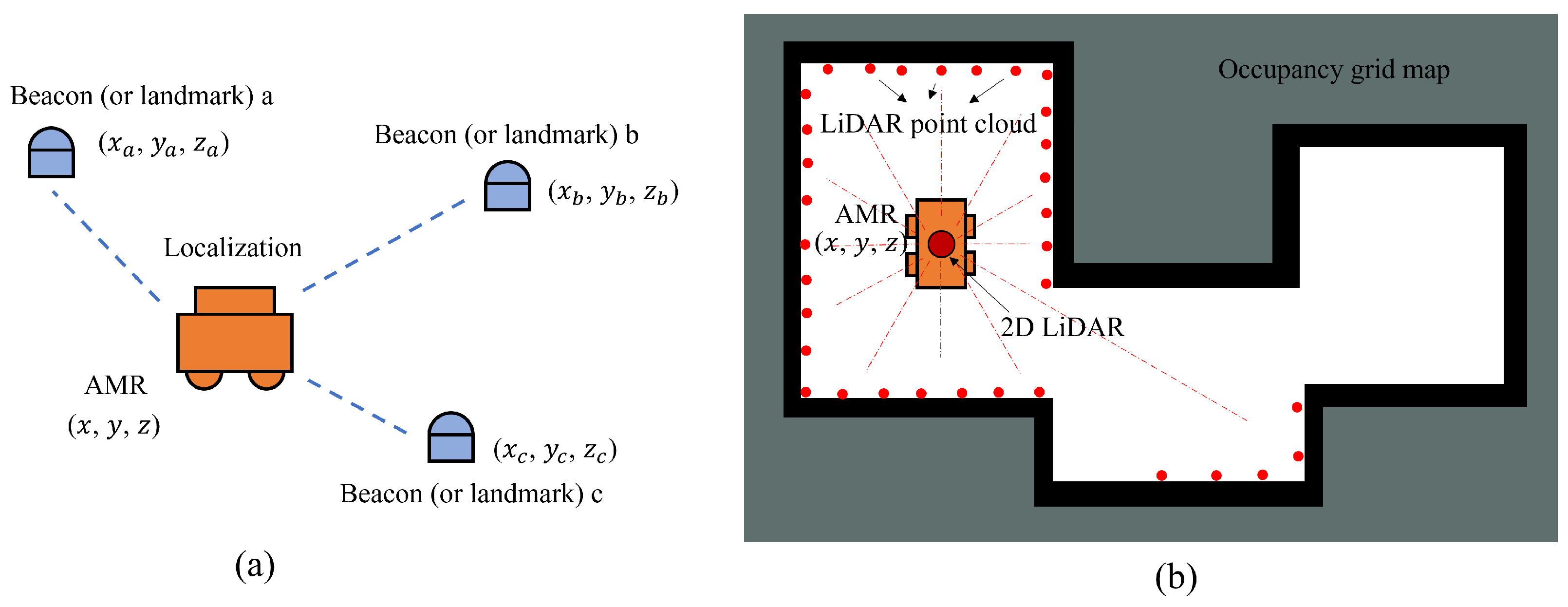
1. Introduction
2. Overview of Single Sensor Sensing Technologies
2.1. Inertial Measurement Unit (IMU)
- The calculation process must depend on the initial conditions.
- The navigation error increases with time, which is due to the need for double integration of its measurements.
2.2. Ultrasonic Sensor/Sonar
2.3. Infrared Sensor
2.4. LiDAR
2.5. Vision-Based Sensor
- 1:
- Eliminating image distortion.
- 2:
- Assigning semantic labels to specific objects. The extraction of specific objects or features in the picture can be achieved by neural networks or traditional feature extraction algorithms. Assigning semantic labels to them is more suitable for human understanding of environmental features.
- 3:
- Image Partial Reconstruction. In indoor environments, deep learning techniques like generative adversarial networks (GAN) and diffusion should be considered for reconstructing specific images due to the significant impact of light and dynamic objects on environmental representation. This reduces or reconstructs interfering factors in the image for the map construction process, such as dynamic objects, visible light, and shadows from occlusions. The goal is to acquire suitable images for scene localization.
- 1:
- The ability to effectively represent the characteristics of the surrounding environment.
- 2:
- The amount of computation and storage required can match the hardware carried by the robot.
- 3:
- The ability to achieve the functionality required by the mobile robot.
2.6. Radio Frequency Technologies
2.6.1. Radio Frequency Technology Localization Algorithms
2.6.2. WiFi
2.6.3. Zigbee
2.6.4. Bluetooth
2.6.5. Ultra-Wideband (UWB)
2.6.6. Radio Frequency Identification (RFID)
2.7. Summary and Discussion
3. Overview of Multi-Sensor Fusion Sensing Technologies
3.1. Multi-Sensor Fusion Algorithm Based on Kalman Filter
3.2. Multi-Sensor Fusion Algorithm Based on Particle Filter
3.3. Multi-Sensor Fusion Algorithm Based on Neural Network
3.4. Other Multi-Sensor Fusion Algorithms
4. Discussions and Future Trends
4.1. Discussions
4.2. Future Trends
- 1:
- Multi-source Information Fusion. The study and development of mobile robots have extended their possible applications, along with increased demands for their usage. However, a single sensor may struggle to satisfy the navigation requirements of complex scenes due to its inherent limitations. Along this line, then, multi-sensor fusion becomes a crucial area of research and development for indoor AMR. Multi-sensor fusion can improve the accuracy, efficiency, and stability of localization, map building, and obstacle detection by providing more comprehensive environmental information to the perception system. Multi-sensor fusion provides accurate and comprehensive information to the decision-making system, enabling mobile robots to adapt better to complex environments and complete navigation tasks more efficiently and robustly.
- 2:
- Flexible and efficient optimization strategies. When mobile robots work in various complex and dynamic environments, there is a large amount of unknown model noise and roughness in the observation information obtained by sensors. To ensure the efficiency, stability, and accuracy of the AMR system, appropriate optimization strategies should be explored based on the specific environment and dynamic changes. In addition, there are many complex nonlinear operations in the optimization process. To improve computational efficiency when dealing with large-scale or multi-modal data, methods such as parallel computing and distributed computing can be adopted.
- 3:
- Integration with neural networks. Since neural networks are able to enhance the stability of mobile robot systems, the combination of relevant neural networks and mobile robots has attracted significant interest. Additionally, the self-learning capabilities of neural networks can address sensor interference and external environmental factors, thereby improving localization anti-interference ability. However, current neural network-based algorithms still encounter limitations for localizing in various indoor scenarios. When employing the same neural network algorithm, the mobile robot experiences significant errors in varying environments. Further research should explore the combination of additional sensors and the application of more complex neural network structures to meet the navigation requirements in diverse indoor environments. With the emergence of large-scale language models and advancements in chip technology, neural network-based approaches are expected to rapidly expand in the future.
Author Contributions
Funding
Conflicts of Interest
References
- Qu, Y.; Yang, M.; Zhang, J.; Xie, W.; Qiang, B.; Chen, J. An Outline of Multi-Sensor Fusion Methods for Mobile Agents Indoor Navigation. Sensors 2021, 21, 1605. [Google Scholar] [CrossRef]
- Bose, D.; Mohan, K.; Cs, M.; Yadav, M.; Saini, D.K. Review of Autonomous Campus and Tour Guiding Robots with Navigation Techniques. Aust. J. Mech. Eng. 2022, 21, 1580–1590. [Google Scholar] [CrossRef]
- Alatise, M.B.; Hancke, G.P. A Review on Challenges of Autonomous Mobile Robot and Sensor Fusion Methods. IEEE Access 2020, 8, 39830–39846. [Google Scholar] [CrossRef]
- Rubio, F.; Valero, F.; Llopis-Albert, C. A review of mobile robots: Concepts, methods, theoretical framework, and applications. Int. J. Adv. Robot. Syst. 2019, 16, 172988141983959. [Google Scholar] [CrossRef]
- Kortenkamp, D. Perception for mobile robot navigation: A survey of the state of the art. In Proceedings of the InDual-Use Space Technology Transfer Conference and Exhibition, Houston, TX, USA, 1 May 1994; Volume 2. [Google Scholar]
- Obeidat, H.; Shuaieb, W.; Obeidat, O.; Abd-Alhameed, R. A Review of Indoor Localization Techniques and Wireless Technologies. Wirel. Pers. Commun. 2021, 119, 289–327. [Google Scholar] [CrossRef]
- Panigrahi, P.K.; Bisoy, S.K. Localization strategies for autonomous mobile robots: A review. J. King Saud Univ. Comput. Inf. Sci. 2022, 34, 6019–6039. [Google Scholar] [CrossRef]
- Huang, J.; Junginger, S.; Liu, H.; Thurow, K. Indoor Positioning Systems of Mobile Robots: A Review. Robotics 2023, 12, 47. [Google Scholar] [CrossRef]
- Kim Geok, T.; Zar Aung, K.; Sandar Aung, M.; Thu Soe, M.; Abdaziz, A.; Pao Liew, C.; Hossain, F.; Tso, C.P.; Yong, W.H. Review of Indoor Positioning: Radio Wave Technology. Appl. Sci. 2020, 11, 279. [Google Scholar] [CrossRef]
- Han, X.; Li, S.; Wang, X.; Zhou, W. Semantic Mapping for Mobile Robots in Indoor Scenes: A Survey. Information 2021, 12, 92. [Google Scholar] [CrossRef]
- Chen, W.; Zhou, C.; Shang, G.; Wang, X.; Li, Z.; Xu, C.; Hu, K. SLAM Overview: From Single Sensor to Heterogeneous Fusion. Remote Sens. 2022, 14, 6033. [Google Scholar] [CrossRef]
- Chen, W.; Shang, G.; Ji, A.; Zhou, C.; Wang, X.; Xu, C.; Li, Z.; Hu, K. An Overview on Visual SLAM: From Tradition to Semantic. Remote Sens. 2022, 14, 3010. [Google Scholar] [CrossRef]
- Chou, C.; Li, H.; Song, D. Encoder-Camera-Ground Penetrating Radar Sensor Fusion: Bimodal Calibration and Subsurface Mapping. IEEE Trans. Robot. 2021, 37, 67–81. [Google Scholar] [CrossRef]
- Shi, H.; Shi, L.; Xu, M.; Hwang, K.S. End-to-End Navigation Strategy With Deep Reinforcement Learning for Mobile Robots. IEEE Trans. Ind. Inform. 2020, 16, 2393–2402. [Google Scholar] [CrossRef]
- Zeng, H.; Song, X.; Jiang, S. Multi-Object Navigation Using Potential Target Position Policy Function. IEEE Trans. Image Process. 2023, 32, 2608–2619. [Google Scholar] [CrossRef] [PubMed]
- Wang, Y.; Li, X.; Zhang, J.; Li, S.; Xu, Z.; Zhou, X. Review of wheeled mobile robot collision avoidance under unknown environment. Sci. Prog. 2021, 104, 003685042110377. [Google Scholar] [CrossRef]
- Qin, H.; Shao, S.; Wang, T.; Yu, X.; Jiang, Y.; Cao, Z. Review of Autonomous Path Planning Algorithms for Mobile Robots. Drones 2023, 7, 211. [Google Scholar] [CrossRef]
- Choi, B.S.; Lee, J.J. Mobile robot localization in indoor environment using RFID and sonar fusion system. In Proceedings of the 2009 IEEE/RSJ International Conference on Intelligent Robots and Systems, St. Louis, MO, USA, 10–15 October 2009; pp. 2039–2044. [Google Scholar] [CrossRef]
- Ouyang, M.; Cao, Z.; Guan, P.; Li, Z.; Zhou, C.; Yu, J. Visual-Gyroscope-Wheel Odometry with Ground Plane Constraint for Indoor Robots in Dynamic Environment. IEEE Sens. Lett. 2021, 5, 1–4. [Google Scholar] [CrossRef]
- Morar, A.; Moldoveanu, A.; Mocanu, I.; Moldoveanu, F.; Radoi, I.E.; Asavei, V.; Gradinaru, A.; Butean, A. A Comprehensive Survey of Indoor Localization Methods Based on Computer Vision. Sensors 2020, 20, 2641. [Google Scholar] [CrossRef]
- Li, R.; Du, Z.; Zhao, Y.; Liu, S. Design and implementation of mobile robot ultrasonic localization system. In Proceedings of the 2016 Chinese Control and Decision Conference (CCDC), Yinchuan, China, 28–30 May 2016; pp. 5347–5352. [Google Scholar] [CrossRef]
- Chan, T.H.; Hesse, H.; Ho, S.G. LiDAR-Based 3D SLAM for Indoor Mapping. In Proceedings of the 2021 7th International Conference on Control, Automation and Robotics (ICCAR), Singapore, 23–26 April 2021; pp. 285–289. [Google Scholar] [CrossRef]
- Borodacz, K.; Szczepański, C.; Popowski, S. Review and selection of commercially available IMU for a short time inertial navigation. Aircr. Eng. Aerosp. Technol. 2022, 94, 45–59. [Google Scholar] [CrossRef]
- Luo, L.; Feng, Z.; Hong-Wei, W.; Long, C. Crawler Robot Indoor Positioning Based on a Combination of Bluetooth and IMU. In Proceedings of the 2022 6th International Conference on Robotics, Control and Automation (ICRCA), Xiamen, China, 26–28 February 2022; pp. 34–39. [Google Scholar] [CrossRef]
- Alatise, M.; Hancke, G. Pose Estimation of a Mobile Robot Based on Fusion of IMU Data and Vision Data Using an Extended Kalman Filter. Sensors 2017, 17, 2164. [Google Scholar] [CrossRef]
- Zhang, S.; Tan, X.; Wu, Q. Self-Positioning for Mobile Robot Indoor Navigation Based on Wheel Odometry, Inertia Measurement Unit and Ultra Wideband. In Proceedings of the 2021 5th International Conference on Vision, Image and Signal Processing (ICVISP), Kuala Lumpur, Malaysia, 18–20 December 2021; pp. 105–110. [Google Scholar] [CrossRef]
- Lee, S.J.; Lee, K.; Song, J.B. Development of advanced grid map building model based on sonar geometric reliability for indoor mobile robot localization. In Proceedings of the 2014 11th International Conference on Ubiquitous Robots and Ambient Intelligence (URAI), Kuala Lumpur, Malaysia, 12–15 November 2014; pp. 292–297. [Google Scholar] [CrossRef]
- Liu, H.; Sun, F.; Fang, B.; Zhang, X. Robotic Room-Level Localization Using Multiple Sets of Sonar Measurements. IEEE Trans. Instrum. Meas. 2017, 66, 2–13. [Google Scholar] [CrossRef]
- Liu, Y.; Fan, R.; Yu, B.; Bocus, M.J.; Liu, M.; Ni, H.; Fan, J.; Mao, S. Mobile Robot Localisation and Navigation Using LEGO NXT and Ultrasonic Sensor. In Proceedings of the 2018 IEEE International Conference on Robotics and Biomimetics (ROBIO), Kuala Lumpur, Malaysia, 12–15 December 2018; pp. 1088–1093. [Google Scholar] [CrossRef]
- Shen, M.; Wang, Y.; Jiang, Y.; Ji, H.; Wang, B.; Huang, Z. A New Positioning Method Based on Multiple Ultrasonic Sensors for Autonomous Mobile Robot. Sensors 2019, 20, 17. [Google Scholar] [CrossRef]
- Hsu, C.C.; Chen, H.C.; Wong, C.C.; Lai, C.Y. Omnidirectional Ultrasonic Localization for Mobile Robots. Sens. Mater. 2022, 34, 453. [Google Scholar] [CrossRef]
- Yuan, S.; Guo, P.; Han, X.; Luan, F.; Zhang, F.; Liu, T.; Mao, H. DSmT-Based Ultrasonic Detection Model for Estimating Indoor Environment Contour. IEEE Trans. Instrum. Meas. 2020, 69, 4002–4014. [Google Scholar] [CrossRef]
- Takai, H.; Miyake, M.; Okuda, K.; Tachibana, K. A simple obstacle arrangement detection algorithm for indoor mobile robots. In Proceedings of the 2010 2nd International Asia Conference on Informatics in Control, Automation and Robotics (CAR 2010), Wuhan, China, 6–7 March 2010; pp. 110–113. [Google Scholar] [CrossRef]
- Jean, J.H.; Wang, J.L. Development of an indoor patrol robot based on ultrasonic and vision data fusion. In Proceedings of the 2013 IEEE International Conference on Mechatronics and Automation, Takamatsu, Japan, 4–7 August 2013; pp. 1234–1238. [Google Scholar] [CrossRef]
- Grami, T.; Sghaier Tlili, A. Indoor Mobile Robot Localization based on a Particle Filter Approach. In Proceedings of the 2019 19th International Conference on Sciences and Techniques of Automatic Control and Computer Engineering (STA), Sousse, Tunisia, 24–26 March 2019; pp. 47–52. [Google Scholar] [CrossRef]
- Derkach, M.; Matiuk, D.; Skarga-Bandurova, I. Obstacle Avoidance Algorithm for Small Autonomous Mobile Robot Equipped with Ultrasonic Sensors. In Proceedings of the 2020 IEEE 11th International Conference on Dependable Systems, Services and Technologies (DESSERT), Kyiv, Ukraine, 14–18 May 2020; pp. 236–241. [Google Scholar] [CrossRef]
- Brassart, E.; Pegard, C.; Mouaddib, M. Localization using infrared beacons. Robotica 2000, 18, 153–161. [Google Scholar] [CrossRef]
- Krejsa, J.; Vechet, S. Infrared Beacons based Localization of Mobile Robot. Electron. Electr. Eng. 2012, 117, 17–22. [Google Scholar] [CrossRef]
- Li, T.H.; Chang, S.J.; Tong, W. Fuzzy Target Tracking Control of Autonomous Mobile Robots by Using Infrared Sensors. IEEE Trans. Fuzzy Syst. 2004, 12, 491–501. [Google Scholar] [CrossRef]
- Juang, J.; Yang, Y. Fuzzy Sensor Fusion and Curve Approximation for indoor Map Building. In Proceedings of the 2015 International Conference on Artificial Intelligence and Industrial Engineering, Phuket, Thailand, 26–27 July 2015. [Google Scholar] [CrossRef]
- Oultiligh, A.; Ayad, H.; Pozna, C.; Mogan, G.; ELbouzekraoui, M.; Elkari, B. Obstacle Avoidance using Fuzzy Controller for Unicycle Robot. In Proceedings of the 2020 International Conference on Control, Automation and Diagnosis (ICCAD), Paris, France, 7–9 October 2020; pp. 1–6. [Google Scholar] [CrossRef]
- Solano, D.M.; Grande, R.E.; Bonilla, M.N.I. PID Control and Fuzzy Logic System to the Obstacle Avoidance in an Autonomous Robot. In Proceedings of the 2021 18th International Conference on Electrical Engineering, Computing Science and Automatic Control (CCE), Mexico City, Mexico, 10–12 November 2021; pp. 1–6. [Google Scholar] [CrossRef]
- Nnoli, K.P.; Benyeogor, M.S.; Bolu, J.I.; Olakanmi, O.O. Edge-Based Infrared-Ultrasonic Anti-Collision Radar System for Robotic Navigation: *Applications of Cost-effective Bisensory System for Obstacle Detection, Tracking, and Avoidance. In Proceedings of the 2022 IEEE International Symposium on Technologies for Homeland Security (HST), Boston, MA, USA, 14–15 November 2022; pp. 1–7. [Google Scholar] [CrossRef]
- Zhao, J.; Fang, J.; Wang, S.; Wang, K.; Liu, C.; Han, T. Obstacle Avoidance of Multi-Sensor Intelligent Robot Based on Road Sign Detection. Sensors 2021, 21, 6777. [Google Scholar] [CrossRef]
- Habich, T.L.; Stuede, M.; Labbe, M.; Spindeldreier, S. Have I been here before? Learning to Close the Loop with LiDAR Data in Graph-Based SLAM. In Proceedings of the 2021 IEEE/ASME International Conference on Advanced Intelligent Mechatronics (AIM), Delft, The Netherlands, 12–16 July 2021; pp. 504–510. [Google Scholar] [CrossRef]
- Meng, J.; Wan, L.; Wang, S.; Jiang, L.; Li, G.; Wu, L.; Xie, Y. Efficient and Reliable LiDAR-Based Global Localization of Mobile Robots Using Multiscale/Resolution Maps. IEEE Trans. Instrum. Meas. 2021, 70, 1–15. [Google Scholar] [CrossRef]
- Hähnel, D.; Burgard, W.; Thrun, S. Learning compact 3D models of indoor and outdoor environments with a mobile robot. Robot. Auton. Syst. 2003, 44, 15–27. [Google Scholar] [CrossRef]
- Wang, X.; Marcotte, R.J.; Olson, E. GLFP: Global Localization from a Floor Plan. In Proceedings of the 2019 IEEE/RSJ International Conference on Intelligent Robots and Systems (IROS), Macau, China, 3–8 November 2019; pp. 1627–1632. [Google Scholar] [CrossRef]
- Kuang, H.; Chen, X.; Guadagnino, T.; Zimmerman, N.; Behley, J.; Stachniss, C. IR-MCL: Implicit Representation-Based Online Global Localization. IEEE Robot. Autom. Lett. 2023, 8, 1627–1634. [Google Scholar] [CrossRef]
- Kim, J.; Chung, W. Localization of a Mobile Robot Using a Laser Range Finder in a Glass-Walled Environment. IEEE Trans. Ind. Electron. 2016, 63, 3616–3627. [Google Scholar] [CrossRef]
- Grisetti, G.; Stachniss, C.; Burgard, W. Improved Techniques for Grid Mapping With Rao-Blackwellized Particle Filters. IEEE Trans. Robot. 2007, 23, 34–46. [Google Scholar] [CrossRef]
- Kohlbrecher, S.; Von Stryk, O.; Meyer, J.; Klingauf, U. A flexible and scalable SLAM system with full 3D motion estimation. In Proceedings of the 2011 IEEE International Symposium on Safety, Security, and Rescue Robotics, Kyoto, Japan, 1–5 November 2011; pp. 155–160. [Google Scholar] [CrossRef]
- Konolige, K.; Grisetti, G.; Kümmerle, R.; Burgard, W.; Limketkai, B.; Vincent, R. Efficient Sparse Pose Adjustment for 2D mapping. In Proceedings of the 2010 IEEE/RSJ International Conference on Intelligent Robots and Systems, Taipei, Taiwan, 18–22 October 2010; pp. 22–29. [Google Scholar] [CrossRef]
- Hess, W.; Kohler, D.; Rapp, H.; Andor, D. Real-time loop closure in 2D LIDAR SLAM. In Proceedings of the 2016 IEEE International Conference on Robotics and Automation (ICRA), Stockholm, Sweden, 16–21 May 2016; pp. 1271–1278. [Google Scholar] [CrossRef]
- Xiang, Y.; Yang, X.Q.; Yang, W.W.; Miao, W.H. Localization and Mapping Algorithm for the Indoor Mobile Robot Based on LIDAR. IOP Conf. Ser. Mater. Sci. Eng. 2020, 831, 012021. [Google Scholar] [CrossRef]
- Wang, H.; Wang, C.; Xie, L. Intensity-SLAM: Intensity Assisted Localization and Mapping for Large Scale Environment. IEEE Robot. Autom. Lett. 2021, 6, 1715–1721. [Google Scholar] [CrossRef]
- Tian, Y.; Liu, X.; Li, L.; Wang, W. Intensity-Assisted ICP for Fast Registration of 2D-LIDAR. Sensors 2019, 19, 2124. [Google Scholar] [CrossRef]
- Hu, W.; Zhang, K.; Shao, L.; Lin, Q.; Hua, Y.; Qin, J. Clustering Denoising of 2D LiDAR Scanning in Indoor Environment Based on Keyframe Extraction. Sensors 2022, 23, 18. [Google Scholar] [CrossRef]
- Jiang, S.; Wang, S.; Yi, Z.; Zhang, M.; Lv, X. Autonomous Navigation System of Greenhouse Mobile Robot Based on 3D Lidar and 2D Lidar SLAM. Front. Plant Sci. 2022, 13, 815218. [Google Scholar] [CrossRef]
- Guan, W.; Huang, L.; Wen, S.; Yan, Z.; Liang, W.; Yang, C.; Liu, Z. Robot Localization and Navigation Using Visible Light Positioning and SLAM Fusion. J. Light. Technol. 2021, 39, 7040–7051. [Google Scholar] [CrossRef]
- Lee, J.; Tsubouchi, T.; Yamamoto, K.; Egawa, S. People Tracking Using a Robot in Motion with Laser Range Finder. In Proceedings of the 2006 IEEE/RSJ International Conference on Intelligent Robots and Systems, Beijing, China, 9–15 October 2006; pp. 2936–2942. [Google Scholar] [CrossRef]
- Mozos, O.M.; Kurazume, R.; Hasegawa, T. Multi-Part People Detection Using 2D Range Data. Int. J. Soc. Robot. 2010, 2, 31–40. [Google Scholar] [CrossRef]
- Guerrero-Higueras, Á.M.; Álvarez Aparicio, C.; Calvo Olivera, M.C.; Rodríguez-Lera, F.J.; Fernández-Llamas, C.; Rico, F.M.; Matellán, V. Tracking People in a Mobile Robot From 2D LIDAR Scans Using Full Convolutional Neural Networks for Security in Cluttered Environments. Front. Neurorobot. 2019, 12, 85. [Google Scholar] [CrossRef]
- Yan, Z.; Duckett, T.; Bellotto, N. Online learning for 3D LiDAR-based human detection: Experimental analysis of point cloud clustering and classification methods. Auton. Robot. 2020, 44, 147–164. [Google Scholar] [CrossRef]
- Li, Z.; Wang, C.; Yan, W.; Ji, Y.; Zou, A.; Lai, J. Research on obstacle detection and location of indoor robot based on LIDAR. In Proceedings of the 9th International Symposium on Advanced Optical Manufacturing and Testing Technologies: Optical Test, Measurement Technology, and Equipment, Chengdu, China, 26–29 June 2019; p. 31. [Google Scholar] [CrossRef]
- Henry, P.; Krainin, M.; Herbst, E.; Ren, X.; Fox, D. RGB-D Mapping: Using Depth Cameras for Dense 3D Modeling of Indoor Environments. In Experimental Robotics; Khatib, O., Kumar, V., Sukhatme, G., Eds.; Springer: Berlin/Heidelberg, Germany, 2014; Volume 79, pp. 477–491. [Google Scholar] [CrossRef]
- Wimbauer, F.; Yang, N.; Von Stumberg, L.; Zeller, N.; Cremers, D. MonoRec: Semi-Supervised Dense Reconstruction in Dynamic Environments from a Single Moving Camera. In Proceedings of the 2021 IEEE/CVF Conference on Computer Vision and Pattern Recognition (CVPR), Nashville, TN, USA, 20–25 June 2021; pp. 6108–6118. [Google Scholar] [CrossRef]
- Campos, C.; Elvira, R.; Rodriguez, J.J.G.; Montiel, J.M.M.; Tardos, J.D. ORB-SLAM3: An Accurate Open-Source Library for Visual, Visual–Inertial, and Multimap SLAM. IEEE Trans. Robot. 2021, 37, 1874–1890. [Google Scholar] [CrossRef]
- Li, Y.; Liu, X.; Dong, W.; Zhou, H.; Bao, H.; Zhang, G.; Zhang, Y.; Cui, Z. DELTAR: Depth Estimation from a Light-weight ToF Sensor and RGB Image. arXiv 2022, arXiv:2209.13362. [Google Scholar]
- Davison, A.J.; Reid, I.D.; Molton, N.D.; Stasse, O. MonoSLAM: Real-Time Single Camera SLAM. IEEE Trans. Pattern Anal. Mach. Intell. 2007, 29, 1052–1067. [Google Scholar] [CrossRef] [PubMed]
- Konolige, K.; Agrawal, M. FrameSLAM: From Bundle Adjustment to Real-Time Visual Mapping. IEEE Trans. Robot. 2008, 24, 1066–1077. [Google Scholar] [CrossRef]
- Newcombe, R.A.; Fitzgibbon, A.; Izadi, S.; Hilliges, O.; Molyneaux, D.; Kim, D.; Davison, A.J.; Kohi, P.; Shotton, J.; Hodges, S. KinectFusion: Real-time dense surface mapping and tracking. In Proceedings of the 2011 10th IEEE International Symposium on Mixed and Augmented Reality, Basel, Switzerland, 26–29 October 2011; pp. 127–136. [Google Scholar] [CrossRef]
- Rebecq, H.; Horstschaefer, T.; Gallego, G.; Scaramuzza, D. EVO: A Geometric Approach to Event-Based 6-DOF Parallel Tracking and Mapping in Real Time. IEEE Robot. Autom. Lett. 2017, 2, 593–600. [Google Scholar] [CrossRef]
- Bajpayee, A.; Techet, A.H.; Singh, H. Real-Time Light Field Processing for Autonomous Robotics. In Proceedings of the 2018 IEEE/RSJ International Conference on Intelligent Robots and Systems (IROS), Madrid, Spain, 1–5 October 2018; pp. 4218–4225. [Google Scholar] [CrossRef]
- Liu, L.; Song, X.; Wang, M.; Liu, Y.; Zhang, L. Self-supervised Monocular Depth Estimation for All Day Images using Domain Separation. arXiv 2021, arXiv:2108.07628. [Google Scholar]
- Bescos, B.; Cadena, C.; Neira, J. Empty Cities: A Dynamic-Object-Invariant Space for Visual SLAM. IEEE Trans. Robot. 2021, 37, 433–451. [Google Scholar] [CrossRef]
- Tourani, A.; Bavle, H.; Sanchez-Lopez, J.L.; Voos, H. Visual SLAM: What Are the Current Trends and What to Expect? Sensors 2022, 22, 9297. [Google Scholar] [CrossRef]
- Zhan, H.; Weerasekera, C.S.; Bian, J.W.; Reid, I. Visual Odometry Revisited: What Should Be Learnt? In Proceedings of the 2020 IEEE International Conference on Robotics and Automation (ICRA), Paris, France, 31 May–31 August 2020; pp. 4203–4210. [Google Scholar] [CrossRef]
- Zhou, Y.; Gallego, G.; Shen, S. Event-Based Stereo Visual Odometry. IEEE Trans. Robot. 2021, 37, 1433–1450. [Google Scholar] [CrossRef]
- Zhu, Z.; Peng, S.; Larsson, V.; Xu, W.; Bao, H.; Cui, Z.; Oswald, M.R.; Pollefeys, M. NICE-SLAM: Neural Implicit Scalable Encoding for SLAM. In Proceedings of the 2022 IEEE/CVF Conference on Computer Vision and Pattern Recognition (CVPR), New Orleans, LA, USA, 18–24 June 2022; pp. 12776–12786. [Google Scholar] [CrossRef]
- Zheng, C.; Zhu, Q.; Xu, W.; Liu, X.; Guo, Q.; Zhang, F. FAST-LIVO: Fast and Tightly-coupled Sparse-Direct LiDAR-Inertial-Visual Odometry. In Proceedings of the 2022 IEEE/RSJ International Conference on Intelligent Robots and Systems (IROS), Kyoto, Japan, 23–27 October 2022; pp. 4003–4009. [Google Scholar] [CrossRef]
- Wu, M.; Wang, S.; Meng, J.; Xie, Y. AprilTag-Aided Pose Estimation Optimization of Landmark VSLAM. In Proceedings of the 2023 42nd Chinese Control Conference (CCC), Tianjin, China, 24–26 July 2023; pp. 4556–4561. [Google Scholar] [CrossRef]
- Schreiber, M.; Belagiannis, V.; Glaser, C.; Dietmayer, K. Dynamic Occupancy Grid Mapping with Recurrent Neural Networks. In Proceedings of the 2021 IEEE International Conference on Robotics and Automation (ICRA), Xi’an, China, 30 May–5 June 2021; pp. 6717–6724. [Google Scholar] [CrossRef]
- Eisoldt, M.; Flottmann, M.; Gaal, J.; Buschermohle, P.; Hinderink, S.; Hillmann, M.; Nitschmann, A.; Hoffmann, P.; Wiemann, T.; Porrmann, M. HATSDF SLAM—Hardware-accelerated TSDF SLAM for Reconfigurable SoCs. In Proceedings of the 2021 European Conference on Mobile Robots (ECMR), Bonn, Germany, 31 August–3 September 2021; pp. 1–7. [Google Scholar] [CrossRef]
- Rosinol, A.; Abate, M.; Chang, Y.; Carlone, L. Kimera: An Open-Source Library for Real-Time Metric-Semantic Localization and Mapping. In Proceedings of the 2020 IEEE International Conference on Robotics and Automation (ICRA), Paris, France, 31 May–31 August 2020; pp. 1689–1696. [Google Scholar] [CrossRef]
- Vijayanarasimhan, S.; Ricco, S.; Schmid, C.; Sukthankar, R.; Fragkiadaki, K. SfM-Net: Learning of Structure and Motion from Video. arXiv 2017, arXiv:1704.07804. [Google Scholar]
- Cao, A.Q.; De Charette, R. MonoScene: Monocular 3D Semantic Scene Completion. In Proceedings of the 2022 IEEE/CVF Conference on Computer Vision and Pattern Recognition (CVPR), New Orleans, LA, USA, 18–24 June 2022; pp. 3981–3991. [Google Scholar] [CrossRef]
- Kim, H.; Moon, J.; Lee, B. RGB-to-TSDF: Direct TSDF Prediction from a Single RGB Image for Dense 3D Reconstruction. In Proceedings of the 2019 IEEE/RSJ International Conference on Intelligent Robots and Systems (IROS), Macau, China, 3–8 November 2019; pp. 6714–6720. [Google Scholar] [CrossRef]
- Yu, C.; Liu, Z.; Liu, X.J.; Xie, F.; Yang, Y.; Wei, Q.; Fei, Q. DS-SLAM: A Semantic Visual SLAM towards Dynamic Environments. In Proceedings of the 2018 IEEE/RSJ International Conference on Intelligent Robots and Systems (IROS), Madrid, Spain, 1–5 October 2018; pp. 1168–1174. [Google Scholar] [CrossRef]
- Kulhanek, J.; Derner, E.; De Bruin, T.; Babuska, R. Vision-based Navigation Using Deep Reinforcement Learning. In Proceedings of the 2019 European Conference on Mobile Robots (ECMR), Prague, Czech Republic, 4–6 September 2019; pp. 1–8. [Google Scholar] [CrossRef]
- Xiao, W.; Yuan, L.; He, L.; Ran, T.; Zhang, J.; Cui, J. Multigoal Visual Navigation With Collision Avoidance via Deep Reinforcement Learning. IEEE Trans. Instrum. Meas. 2022, 71, 1–9. [Google Scholar] [CrossRef]
- Xie, L.; Markham, A.; Trigoni, N. SnapNav: Learning Mapless Visual Navigation with Sparse Directional Guidance and Visual Reference. In Proceedings of the 2020 IEEE International Conference on Robotics and Automation (ICRA), Paris, France, 31 May–31 August 2020; pp. 1682–1688. [Google Scholar] [CrossRef]
- Tai, L.; Li, S.; Liu, M. A deep-network solution towards model-less obstacle avoidance. In Proceedings of the 2016 IEEE/RSJ International Conference on Intelligent Robots and Systems (IROS), Daejeon, Republic of Korea, 9–14 October 2016; pp. 2759–2764. [Google Scholar] [CrossRef]
- De Cristóforis, P.; Nitsche, M.; Krajník, T.; Pire, T.; Mejail, M. Hybrid vision-based navigation for mobile robots in mixed indoor/outdoor environments. Pattern Recognit. Lett. 2015, 53, 118–128. [Google Scholar] [CrossRef]
- Biswas, J.; Veloso, M.M. WiFi Localization and Navigation for Autonomous Indoor Mobile Robots. In Proceedings of the 2010 IEEE International Conference on Robotics and Automation, Anchorage, AK, USA, 3–7 May 2010; pp. 4379–4384. [Google Scholar] [CrossRef]
- Schwarz, D.; Schwarz, M.; Stückler, J.; Behnke, S. Cosero, Find My Keys! Object Localization and Retrieval Using Bluetooth Low Energy Tags. In RoboCup 2014: Robot World Cup XVIII; Bianchi, R.A.C., Akin, H.L., Ramamoorthy, S., Sugiura, K., Eds.; Series Title: Lecture Notes in Computer Science; Springer International Publishing: Cham, Germany, 2015; Volume 8992, pp. 195–206. [Google Scholar] [CrossRef]
- Loganathan, A.; Ahmad, N.S. Self-Adaptive Filtering Approach for Improved Indoor Localization of a Mobile Node with Zigbee-Based RSSI and Odometry. Sensors 2019, 19, 4748. [Google Scholar] [CrossRef]
- Xin, J.; Xie, G.; Yan, B.; Shan, M.; Li, P.; Gao, K. Multimobile Robot Cooperative Localization Using Ultrawideband Sensor and GPU Acceleration. IEEE Trans. Autom. Sci. Eng. 2022, 19, 2699–2710. [Google Scholar] [CrossRef]
- Yang, B.; Yang, E. A Survey on Radio Frequency based Precise Localisation Technology for UAV in GPS-denied Environment. J. Intell. Robot. Syst. 2021, 103, 38. [Google Scholar] [CrossRef]
- Shen, J.; Junyang, S.; Molisch, A.F.; Salmi, J. Accurate Passive Location Estimation Using TOA Measurements. IEEE Trans. Wirel. Commun. 2012, 11, 2182–2192. [Google Scholar] [CrossRef]
- Guvenc, I.; Chong, C.C. A Survey on TOA Based Wireless Localization and NLOS Mitigation Techniques. IEEE Commun. Surv. Tutorials 2009, 11, 107–124. [Google Scholar] [CrossRef]
- Ho, K.C. Bias Reduction for an Explicit Solution of Source Localization Using TDOA. IEEE Trans. Signal Process. 2012, 60, 2101–2114. [Google Scholar] [CrossRef]
- Zafari, F.; Gkelias, A.; Leung, K.K. A Survey of Indoor Localization Systems and Technologies. IEEE Commun. Surv. Tutorials 2019, 21, 2568–2599. [Google Scholar] [CrossRef]
- Wang, Y.; Ho, K.C. An Asymptotically Efficient Estimator in Closed-Form for 3-D AOA Localization Using a Sensor Network. IEEE Trans. Wirel. Commun. 2015, 14, 6524–6535. [Google Scholar] [CrossRef]
- Mazuelas, S.; Bahillo, A.; Lorenzo, R.M.; Fernandez, P.; Lago, F.A.; Garcia, E.; Blas, J.; Abril, E.J. Robust Indoor Positioning Provided by Real-Time RSSI Values in Unmodified WLAN Networks. IEEE J. Sel. Top. Signal Process. 2009, 3, 821–831. [Google Scholar] [CrossRef]
- He, S.; Chan, S.H.G. Wi-Fi Fingerprint-Based Indoor Positioning: Recent Advances and Comparisons. IEEE Commun. Surv. Tutorials 2016, 18, 466–490. [Google Scholar] [CrossRef]
- Davidson, P.; Piche, R. A Survey of Selected Indoor Positioning Methods for Smartphones. IEEE Commun. Surv. Tutorials 2017, 19, 1347–1370. [Google Scholar] [CrossRef]
- Ye, H.; Peng, J. Robot Indoor Positioning and Navigation Based on Improved WiFi Location Fingerprint Positioning Algorithm. Wirel. Commun. Mob. Comput. 2022, 2022, 8274455. [Google Scholar] [CrossRef]
- Zhang, L.; Chen, Z.; Cui, W.; Li, B.; Chen, C.; Cao, Z.; Gao, K. WiFi-Based Indoor Robot Positioning Using Deep Fuzzy Forests. IEEE Internet Things J. 2020, 7, 10773–10781. [Google Scholar] [CrossRef]
- Zhou, G.; Xu, S.; Zhang, S.; Wang, Y.; Xiang, C. Multi-Floor Indoor Localization Based on Multi-Modal Sensors. Sensors 2022, 22, 4162. [Google Scholar] [CrossRef] [PubMed]
- Zhang, L.; Zhang, S.; Leng, C.T. A Study on the Location System Based on Zigbee for Mobile Robot. Appl. Mech. Mater. 2014, 651–653, 612–615. [Google Scholar] [CrossRef]
- Wang, Z.; Liu, M.; Zhang, Y. Mobile localization in complex indoor environment based on ZigBee wireless network. J. Phys. 2019, 1314, 012214. [Google Scholar] [CrossRef]
- Raghavan, A.N.; Ananthapadmanaban, H.; Sivamurugan, M.S.; Ravindran, B. Accurate mobile robot localization in indoor environments using bluetooth. In Proceedings of the 2010 IEEE International Conference on Robotics and Automation, Anchorage, AK, USA, 3–7 May 2010; pp. 4391–4396. [Google Scholar] [CrossRef]
- Yamami, Y.; Tang, S. AoA Estimation for High Accuracy BLE Positioning. In Proceedings of the IEEE Consumer Communications and Networking Conference, Las Vegas, NV, USA, 8–11 January 2023. [Google Scholar] [CrossRef]
- Weinmann, K.; Simske, S. Design of Bluetooth 5.1 Angle of Arrival Homing Controller for Autonomous Mobile Robot. Robotics 2023, 12, 115. [Google Scholar] [CrossRef]
- Alexandr, A.; Anton, D.; Mikhail, M.; Ilya, K. Comparative Analysis of Indoor Positioning Methods Based on the Wireless Sensor Network of Bluetooth Low Energy Beacons. In Proceedings of the 2020 International Conference Engineering and Telecommunication (En &T), Dolgoprudny, Russia, 25–26 November 2020. [Google Scholar] [CrossRef]
- Shi, D.; Mi, H.; Collins, E.G.; Wu, J. An Indoor Low-Cost and High-Accuracy Localization Approach for AGVs. IEEE Access 2020, 8, 50085–50090. [Google Scholar] [CrossRef]
- Leng, J.; Ma, G.; Zhu, J.; Ma, H. Improved TDOA Two-Stage UWB Localization Algorithm For Indoor Mobile Robot. In Proceedings of the IEEE International Conference on Recent Advances in Systems Science and Engineering (IEEE RASSE 2021), Shanghai, China, 12–14 December 2021. [Google Scholar] [CrossRef]
- Li, P.; Xu, Y.; Shen, T.; Bi, S. INS/UWB integrated AGV localization employing Kalman filter for indoor LOS/NLOS mixed environment. In Proceedings of the 2019 International Conference on Advanced Mechatronic Systems (ICAMechS), Kusatsu, Shiga, Japan, 26–28 August 2019; pp. 294–298. [Google Scholar] [CrossRef]
- Xu, T.; Zhang, H.; Zhou, X.; Yuan, X.; Tan, X.; Zhang, J.; Zhong, H. A Weight Adaptive Kalman Filter Localization Method Based on UWB and Odometry. In Proceedings of the 2022 International Conference on Advanced Robotics and Mechatronics (ICARM), Guilin, China, 9–11 July 2022; pp. 956–961. [Google Scholar] [CrossRef]
- Zhou, H.; Yao, Z.; Zhang, Z.; Liu, P.; Lu, M. An Online Multi-Robot SLAM System Based on Lidar/UWB Fusion. IEEE Sens. J. 2022, 22, 2530–2542. [Google Scholar] [CrossRef]
- Wu, H.; Tao, B.; Gong, Z.; Yin, Z.; Ding, H. A Standalone RFID-Based Mobile Robot Navigation Method Using Single Passive Tag. IEEE Trans. Autom. Sci. Eng. 2021, 18, 1529–1537. [Google Scholar] [CrossRef]
- Wang, J.; Takahashi, Y. Particle Smoother-Based Landmark Mapping for the SLAM Method of an Indoor Mobile Robot with a Non-Gaussian Detection Model. J. Sens. 2019, 2019, 3717298. [Google Scholar] [CrossRef]
- Shamsfakhr, F.; Macii, D.; Fontanelli, D.; Motroni, A.; Nepa, P.; Palopoli, L.; Buffi, A. RFID-based robot localisation: An unconstrained optimisation problem by exploiting RSSI. In Proceedings of the 2022 IEEE International Instrumentation and Measurement Technology Conference (I2MTC), Ottawa, ON, Canada, 16–19 May 2022; pp. 1–6. [Google Scholar] [CrossRef]
- Wijk, O.; Christensen, H. Localization and navigation of a mobile robot using natural point landmarks extracted from sonar data. Robot. Auton. Syst. 2000, 31, 31–42. [Google Scholar] [CrossRef]
- Lee, J.S.; Nam, S.Y.; Chung, W.K. Robust RBPF-SLAM for Indoor Mobile Robots Using Sonar Sensors in Non-Static Environments. Adv. Robot. 2011, 25, 1227–1248. [Google Scholar] [CrossRef]
- Arras, K.; Tomatis, N. Improving robustness and precision in mobile robot localization by using laser range finding and monocular vision. In Proceedings of the 1999 Third European Workshop on Advanced Mobile Robots (Eurobot’99). Proceedings (Cat. No.99EX355), Zurich, Switzerland, 6–8 September 1999; pp. 177–185. [Google Scholar] [CrossRef]
- Lingemann, K.; Nüchter, A.; Hertzberg, J.; Surmann, H. High-speed laser localization for mobile robots. Robot. Auton. Syst. 2005, 51, 275–296. [Google Scholar] [CrossRef]
- Choi, B.S.; Lee, J.W.; Lee, J.J.; Park, K.T. A Hierarchical Algorithm for Indoor Mobile Robot Localization Using RFID Sensor Fusion. IEEE Trans. Ind. Electron. 2011, 58, 2226–2235. [Google Scholar] [CrossRef]
- Cho, B.S.; Moon, W.s.; Seo, W.J.; Baek, K.R. A dead reckoning localization system for mobile robots using inertial sensors and wheel revolution encoding. J. Mech. Sci. Technol. 2011, 25, 2907–2917. [Google Scholar] [CrossRef]
- Myung, H.; Lee, H.K.; Choi, K.; Bang, S. Mobile robot localization with gyroscope and constrained Kalman filter. Int. J. Control Autom. Syst. 2010, 8, 667–676. [Google Scholar] [CrossRef]
- Zhang, X.; Xian, B.; Zhao, B.; Zhang, Y. Autonomous Flight Control of a Nano Quadrotor Helicopter in a GPS-Denied Environment Using On-Board Vision. IEEE Trans. Ind. Electron. 2015, 62, 6392–6403. [Google Scholar] [CrossRef]
- López, E.; García, S.; Barea, R.; Bergasa, L.; Molinos, E.; Arroyo, R.; Romera, E.; Pardo, S. A Multi-Sensorial Simultaneous Localization and Mapping (SLAM) System for Low-Cost Micro Aerial Vehicles in GPS-Denied Environments. Sensors 2017, 17, 802. [Google Scholar] [CrossRef]
- Bachrach, A.; Prentice, S.; He, R.; Henry, P.; Huang, A.S.; Krainin, M.; Maturana, D.; Fox, D.; Roy, N. Estimation, planning, and mapping for autonomous flight using an RGB-D camera in GPS-denied environments. Int. J. Robot. Res. 2012, 31, 1320–1343. [Google Scholar] [CrossRef]
- Chowdhary, G.; Johnson, E.N.; Magree, D.; Wu, A.; Shein, A. GPS-denied Indoor and Outdoor Monocular Vision Aided Navigation and Control of Unmanned Aircraft: J. Field Robotics. J. Field Robot. 2013, 30, 415–438. [Google Scholar] [CrossRef]
- Yang, Z.; Shen, S. Monocular Visual–Inertial State Estimation With Online Initialization and Camera–IMU Extrinsic Calibration. IEEE Trans. Autom. Sci. Eng. 2017, 14, 39–51. [Google Scholar] [CrossRef]
- Huh, S.; Shim, D.H.; Kim, J. Integrated navigation system using camera and gimbaled laser scanner for indoor and outdoor autonomous flight of UAVs. In Proceedings of the 2013 IEEE/RSJ International Conference on Intelligent Robots and Systems, Tokyo, Japan, 3–7 November 2013; pp. 3158–3163. [Google Scholar] [CrossRef]
- Magree, D.; Johnson, E.N. Combined laser and vision-aided inertial navigation for an indoor unmanned aerial vehicle. In Proceedings of the 2014 American Control Conference, Portland, OR, USA, 4–6 June 2014; pp. 1900–1905. [Google Scholar] [CrossRef]
- Zong, C.; Ji, Z.; Yu, Y.; Shi, H. Research on Obstacle Avoidance Method for Mobile Robot Based on Multisensor Information Fusion. Sens. Mater. 2020, 32, 1159. [Google Scholar] [CrossRef]
- Mu, L.; Yao, P.; Zheng, Y.; Chen, K.; Wang, F.; Qi, N. Research on SLAM Algorithm of Mobile Robot Based on the Fusion of 2D LiDAR and Depth Camera. IEEE Access 2020, 8, 157628–157642. [Google Scholar] [CrossRef]
- Jiang, P.; Chen, L.; Guo, H.; Yu, M.; Xiong, J. Novel indoor positioning algorithm based on Lidar/inertial measurement unit integrated system. Int. J. Adv. Robot. Syst. 2021, 18, 172988142199992. [Google Scholar] [CrossRef]
- Lin, J.; Zheng, C.; Xu, W.; Zhang, F. R2LIVE: A Robust, Real-time, LiDAR-Inertial-Visual tightly-coupled state Estimator and mapping. arXiv 2021, arXiv:2102.12400. [Google Scholar]
- Xu, W.; Cai, Y.; He, D.; Lin, J.; Zhang, F. FAST-LIO2: Fast Direct LiDAR-Inertial Odometry. IEEE Trans. Robot. 2022, 38, 2053–2073. [Google Scholar] [CrossRef]
- Alhamdi, E.; Hedjar, R. Comparative Study of Two Localization Approaches for Mobile Robots in an Indoor Environment. J. Robot. 2022, 2022, 1999082. [Google Scholar] [CrossRef]
- Xu, S.; Chou, W.; Dong, H. A Robust Indoor Localization System Integrating Visual Localization Aided by CNN-Based Image Retrieval with Monte Carlo Localization. Sensors 2019, 19, 249. [Google Scholar] [CrossRef]
- Ge, G.; Zhang, Y.; Wang, W.; Jiang, Q.; Hu, L.; Wang, Y. Text-MCL: Autonomous Mobile Robot Localization in Similar Environment Using Text-Level Semantic Information. Machines 2022, 10, 169. [Google Scholar] [CrossRef]
- Huang, Y.H.; Lin, C.T. Indoor Localization Method for a Mobile Robot Using LiDAR and a Dual AprilTag. Electronics 2023, 12, 1023. [Google Scholar] [CrossRef]
- Kendall, A.; Grimes, M.; Cipolla, R. PoseNet: A Convolutional Network for Real-Time 6-DOF Camera Relocalization. In Proceedings of the 2015 IEEE International Conference on Computer Vision (ICCV), Santiago, Chile, 7–13 December 2015; pp. 2938–2946. [Google Scholar] [CrossRef]
- Chen, C.; Wang, B.; Lu, C.X.; Trigoni, N.; Markham, A. A Survey on Deep Learning for Localization and Mapping: Towards the Age of Spatial Machine Intelligence. arXiv 2020, arXiv:2006.12567. [Google Scholar]
- Magrin, C.E.; Todt, E. Multi-Sensor Fusion Method Based on Artificial Neural Network for Mobile Robot Self-Localization. In Proceedings of the 2019 Latin American Robotics Symposium (LARS), 2019 Brazilian Symposium on Robotics (SBR) and 2019 Workshop on Robotics in Education (WRE), Rio Grande, Brazil, 23–25 October 2019; pp. 138–143. [Google Scholar] [CrossRef]
- Li, H.; Mao, Y.; You, W.; Ye, B.; Zhou, X. A neural network approach to indoor mobile robot localization. In Proceedings of the 2020 19th International Symposium on Distributed Computing and Applications for Business Engineering and Science (DCABES), Xuzhou, China, 16–19 October 2020; pp. 66–69. [Google Scholar] [CrossRef]
- Li, C.; Wang, S.; Zhuang, Y.; Yan, F. Deep Sensor Fusion Between 2D Laser Scanner and IMU for Mobile Robot Localization. IEEE Sens. J. 2021, 21, 8501–8509. [Google Scholar] [CrossRef]
- Lee, J.; Lee, H.; Oh, J. FusionLoc: Camera-2D LiDAR Fusion Using Multi-Head Self-Attention for End-to-End Serving Robot Relocalization. IEEE Access 2023, 11, 75121–75133. [Google Scholar] [CrossRef]
- Sarcevic, P.; Csik, D.; Odry, A. Indoor 2D Positioning Method for Mobile Robots Based on the Fusion of RSSI and Magnetometer Fingerprints. Sensors 2023, 23, 1855. [Google Scholar] [CrossRef]
- Barreto-Cubero, A.J.; Gómez-Espinosa, A.; Escobedo Cabello, J.A.; Cuan-Urquizo, E.; Cruz-Ramírez, S.R. Sensor Data Fusion for a Mobile Robot Using Neural Networks. Sensors 2021, 22, 305. [Google Scholar] [CrossRef]
- Lv, W.; Kang, Y.; Qin, J. FVO: Floor vision aided odometry. Sci. China Inf. Sci. 2019, 62, 12202. [Google Scholar] [CrossRef]
- Jiang, G.; Yin, L.; Jin, S.; Tian, C.; Ma, X.; Ou, Y. A Simultaneous Localization and Mapping (SLAM) Framework for 2.5D Map Building Based on Low-Cost LiDAR and Vision Fusion. Appl. Sci. 2019, 9, 2105. [Google Scholar] [CrossRef]
- Liu, R.; He, Y.; Yuen, C.; Lau, B.P.L.; Ali, R.; Fu, W.; Cao, Z. Cost-Effective Mapping of Mobile Robot Based on the Fusion of UWB and Short-Range 2-D LiDAR. IEEE/ASME Trans. Mechatron. 2022, 27, 1321–1331. [Google Scholar] [CrossRef]


| Camera Type | Application Time | Characteristic | Advantages and Disadvantages |
|---|---|---|---|
| Monocular Camera | 2007 [70] | Contains only one lens, the basic unit of the visual sensor | Pros: easy to integrate, low cost Cons: cannot directly provide in-depth information |
| Stereo Camera | 2008 [71] | Simultaneous generation of left and right images for stereoscopic visual | Pros: produces two images (left and right), and can be used for stereo visual Cons: calibrates camera, computationally complex, limited depth estimation range |
| RGBD Camera | 2011 [72] | RGB images and depth images can be provided directly | Pros: Provides accurate depth information Cons: Depth information is susceptible to environmental influences |
| Event Camera | 2017 [73] | Uses pixel changes as events. Captures luminance changes with microsecond time resolution | Pros: able to cope with high dynamics and scenes with large lighting variations, low power consumption Cons: requires image pre-processing to obtain traditional image information |
| Light Field Camera | 2017 [74] | Adding microlens arrays to camera lenses to add scale information to monocular cameras | Pros: provides scale information for monocular cameras Cons: high computational volume, difficult to achieve real-time computing |
| RF | Range (m) | Cost | Advantages | Disadvantages |
|---|---|---|---|---|
| WiFi | 250 | high | Implementation simplicity, large coverage, high transmission rate | High power consumption, meterlevel accuracy, vulnerable to NLOS path |
| Zigbee | 100 | medium | Extremely low energy consumption, low system cost | Low transmission rate, high latency, vulnerable to NLOS path |
| Bluetooth | 100 | low | Implementation simplicity, low energy consumption | Small coverage, low transmission rate, vulnerable to NLOS path |
| UWB | 100 | high | High accuracy, extremely high transmission rate, low latency, immune to interference, robustness to NLOS path | High energy consumption and system cost |
| RFID | 5 | low | Extremely low energy consumption, implementation simplicity, low system cost, high accuracy with specific approach | Small coverage, vulnerable to NLOS path |
| Sensors | Advantages | Disadvantages |
|---|---|---|
| IMU | High output frequency, free from environmental interference. | Initial conditions required, error accumulation, accelerometer is susceptible to vibration. |
| Ultrasonic sensor | Low cost, not influenced by transparent or reflective objects | long-range intensity attenuation, vulnerable to ambient noise. |
| Infrared sensor | Low cost. | Susceptible to environmental interference (light source, reflection). |
| LiDAR | High distance measurement accuracy. | Restricted in environments surrounded by transparent or reflective objects. |
| Vision-based sensor | Rich collection of information | Large computational volume, vulnerable to light. |
| Radio Frequency Sensor | Environment and obstacles have less effect on positioning. | Not suitable for unknown or unpredictable environments, unable to measure orientation. |
Disclaimer/Publisher’s Note: The statements, opinions and data contained in all publications are solely those of the individual author(s) and contributor(s) and not of MDPI and/or the editor(s). MDPI and/or the editor(s) disclaim responsibility for any injury to people or property resulting from any ideas, methods, instructions or products referred to in the content. |
© 2024 by the authors. Licensee MDPI, Basel, Switzerland. This article is an open access article distributed under the terms and conditions of the Creative Commons Attribution (CC BY) license (https://creativecommons.org/licenses/by/4.0/).
Share and Cite
Liu, Y.; Wang, S.; Xie, Y.; Xiong, T.; Wu, M. A Review of Sensing Technologies for Indoor Autonomous Mobile Robots. Sensors 2024, 24, 1222. https://doi.org/10.3390/s24041222
Liu Y, Wang S, Xie Y, Xiong T, Wu M. A Review of Sensing Technologies for Indoor Autonomous Mobile Robots. Sensors. 2024; 24(4):1222. https://doi.org/10.3390/s24041222
Chicago/Turabian StyleLiu, Yu, Shuting Wang, Yuanlong Xie, Tifan Xiong, and Mingyuan Wu. 2024. "A Review of Sensing Technologies for Indoor Autonomous Mobile Robots" Sensors 24, no. 4: 1222. https://doi.org/10.3390/s24041222
APA StyleLiu, Y., Wang, S., Xie, Y., Xiong, T., & Wu, M. (2024). A Review of Sensing Technologies for Indoor Autonomous Mobile Robots. Sensors, 24(4), 1222. https://doi.org/10.3390/s24041222