1. Introduction
Orientation sensors, whether standalone or integrated into pose-tracking systems, are extensively used in drones, mobile robots, medical applications [
1], and immersive visualization devices [
2]. These sensors provide absolute measurements, differential rotations, or a combination of both. For instance, Inertial Navigation Systems integrate data from a gyroscope, accelerometer, and magnetometer, while 3D SLAM applications can leverage IMU data alongside odometry for precise localization and mapping.
Sensor systems with stable external references like motion capture cameras, VR tracking devices, and electromagnetic trackers provide reliable absolute orientation with moderate noise levels. However, the increasingly popular MEMS-based and the so-called inside-out vision-based systems are less robust against noise, bias, drift, and delay. For example, concerning MEMS sensors, Shi et al. pointed out that environmental factors, particularly ambient temperature, significantly affect the bias and drift of these sensors, which can lead to decreased orientation estimation accuracy [
3]. Another analysis by Suvorkin et al. utilized the Allan deviation slope method to evaluate noise characteristics across different grades of sensors. This analysis provides insights into the stability and reliability of IMU measurements over time, which is essential for applications requiring high precision [
4]. Understanding noise characteristics is crucial for interpreting IMU data accurately and ensuring its validity in practical applications. With the emergence of more advanced observer-based and dynamic filtering techniques for enhancing raw IMU data, such as those proposed in [
5,
6], the need for repeatable and automated validation methods has become increasingly important.
Inside-out tracking systems, such as those used in Microsoft’s HoloLens or HTC Vive, rely on onboard cameras to track the environment and determine orientation. While these systems offer the advantage of not requiring external infrastructure, they are highly sensitive to environmental conditions, such as lighting and occlusions. A study by Zhang et al. found that inside-out tracking systems could experience substantial errors in orientation estimation when subjected to rapid movements or changes in lighting conditions [
7]. Additionally, the latency introduced by image processing can lead to noticeable delays in orientation updates, impacting user experience. Similarly, a paper by Niehorster et al. on the HTC Vive’s inside-out tracking system highlighted that while the precision of tracking measurements is high, the system can experience significant offsets when tracking is temporarily lost, affecting overall accuracy [
8]. Other studies using the HTV Vive tracker give similar conclusions [
9,
10]. This illustrates the challenges faced by systems that rely on internal measurements compared with those that utilize stable external references.
These imperfections underline the importance of validation methodologies that allow for precise and automatic comparisons of various sensors under multiple conditions in a repeatable way. The validation of orientation sensors relies heavily on the establishment of ground truth data. Ground truth serves as a reference against which the performance of the sensors can be assessed. Various methods for obtaining ground truth have been documented in the literature, each with its unique advantages and applications.
One of the most reliable forms of ground truth for validating IMU orientation sensors is the use of motion capture systems. These systems provide high-precision data regarding the position and orientation of subjects in three-dimensional space. For instance, Morrow et al. conducted a validation study where they compared the kinematic data obtained from a commercially available IMU system against a standard optical motion capture system [
11]. Inside-out tracking systems have been validated in similar setups [
9,
12]. This comparative approach is widely recognized for its effectiveness if a motion capture laboratory is available.
Another approach to obtaining reliable references is the use of mechanical fixtures. The use of fixtures in experimental setups allows for controlled conditions that can significantly enhance the reliability of sensor validation processes. Bliley et al. [
13] described a validation method for wearable motion-sensing devices that involved a mechanical fixture. Their approach utilized a platform rotated by a servo motor, which allowed for precise control over the orientation of the sensors being tested. This method ensured that the sensors were subjected to known and repeatable movements, facilitating accurate comparisons between the sensor outputs and the expected values. Additionally, Eastman et al. [
14] highlighted the importance of using fixtures in their work on 6DoF (six degrees of freedom) object pose ground truth measurements. They employed an aluminum pose fixture along with a laser tracker to establish a reliable reference for validating sensor outputs. This combination of a rigid fixture and precise measurement tools allowed for high accuracy in determining the orientation and position of objects. Similarly, Herickhoff et al. [
15] utilized a lightweight plastic fixture to hold an IMU sensor. The adaptability of such fixtures makes them valuable tools in various applications, including medical imaging and motion analysis.
These published methods lack the ability to provide a programmatic way to generate test motions and then analyze the results in a tractable manner. Using a robot arm as a ground truth reference would provide important benefits: the robot arm can provide precise and repeatable movements, allowing for accurate comparisons between the sensor outputs and the known positions and orientations of the arm. This motivation has been supported by studies from the literature in the field. Schmidt and Kraft noted that accurate ground truth trajectories can be obtained when a camera is mounted on an industrial robot arm, which allows for reliable evaluations of visual SLAM (Simultaneous Localization and Mapping) algorithms [
16]. Several papers, such as [
17,
18,
19], highlight the advantages of using robot arms to create motion patterns for testing IMUs. A notable method proposed by Hoslip et al. employs an industrial robot to evaluate the performance of multiple IMU sensors simultaneously [
20]. However, despite the use of various robotic manipulators, no systematic approach has been published to mathematically address the geometric relationships between the robot’s reference frame and the sensor’s reference frame.
Authors faced this unsolved issue during the experimental validation of a generic direction and orientation tracking method based on an IMU sensor, which has been published in [
21]. In our former work, we proposed a mathematical framework for the calibration and tracking of objects with one functional direction (continuous rotational symmetric case) and multiple functional directions (non-symmetric case). This previous work has inspired the current study which proposes a method for the validation of orientation sensors with respect to an external reference. The proposed method is agnostic to the external (reference) measurement system, but it is discussed considering a robotic arm as a robust integrated actuation and sensing device, and the robotics terminology is used throughout the discussion.
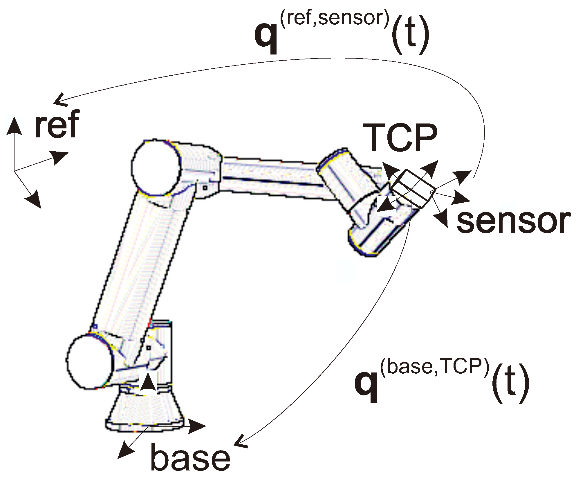
In our setup, a commercial robot arm is employed for validation, providing a precise orientation reference and enabling automated testing capabilities (
Figure 1). This approach not only ensures high accuracy but also facilitates systematic and repeatable validation processes.
The validation of orientation sensors using any test setup introduces the challenge of dealing with different reference and target frames. The sensor initializes its own unknown reference frame and measures the orientation of a frame fixed to the sensor relative to this reference. The analogous frames of an industrial manipulator are called base frame and TCP frame, respectively (see
Figure 2). We can suppose that the industrial robot’s internal measurement system provides reliable position and accurate orientation information regarding the base to TCP transformation [
22,
23].
As its main contribution, this paper proposes a tractable method to approximate the rotation transformation between the robot’s base frame and the sensor frame, as well as between the TCP (Tool Center Point) frame and the sensor frame. The method involves two main steps: first, deriving an initial estimate using geometric principles, followed by a local optimization to minimize the impact of measurement noise and errors. The proposed method relies solely on easily obtainable logged data of the robot’s TCP orientations and the sensor’s outputs, enabling automated and repeatable testing under a wide range of operational conditions and motion dynamics.
To demonstrate the method’s effectiveness, experiments were conducted using a UR16e robot [
24] with two distinct sensors: the widely used ICM20948 IMU sensor [
25] and the HTC VIVE headset’s inside-out tracking system [
8,
26,
27,
28].
This paper is organized as follows:
Section 2 defines the problem and introduces the relevant notations.
Section 3 elaborates on the proposed calibration method.
Section 4 presents experimental results obtained with various sensors and provides a comparative analysis.
Section 5 outlines future research activities and potential practical applications. Finally,
Section 6 summarizes the findings.
Appendix A includes details on vector and quaternion operations, along with their respective notations, as used throughout the paper. Original measurement data associated with the content of this paper can be found at [
29].
2. Problem Description
In the investigated measurement setup, the
orientation can be obtained from the pose of the manipulator, while the sensor provides its
orientation with respect to its own reference frame; see
Figure 2.
Note that the orientation sensor can be attached to the robot’s end-effector in any arbitrary relative orientation. There are no restrictions on this relative orientation, as it does not affect the calibration accuracy. However, it is essential that the relative orientation remains unchanged throughout the entire measurement process.
In an ideal case, there exist
and
orientations such that
for all
. However, in practical scenarios, there is an error resulting from the measurement noises and the drift of the sensor.
In the following, the value (read from the robot controller) will be considered as ground truth. The computation of and orientations from some initial data will be referred to as calibration.
Considering the whole recorded dataset, the angle error of Equation (
1) will be analyzed to obtain the measurement noise and the drift of the sensor.
3. Calibration Method
The calibration is performed using solely the first values of the measured data. This approach enables the analysis of sensor drift in the subsequent measurements for .
The method requires at least three values from the portion of the measured data, each rotated by an angle relative to the others. Denote the time of these measurements as , , and .
The calibration process consists of two stages: first, obtaining a good initial guess using the measurements at , , and ; next, refining this initial estimate with all measurements for . The following subsections provide a detailed description of these steps.
To minimize potential inaccuracies of the calibration resulting from processing and communication delays during the parallel recording of the robot’s and the sensor’s orientations, the robot’s motion program should be designed carefully. Specifically, in the interval, the end-effector should move at a low angular velocity and remain steady at , , and whenever possible.
3.1. Initial Guess
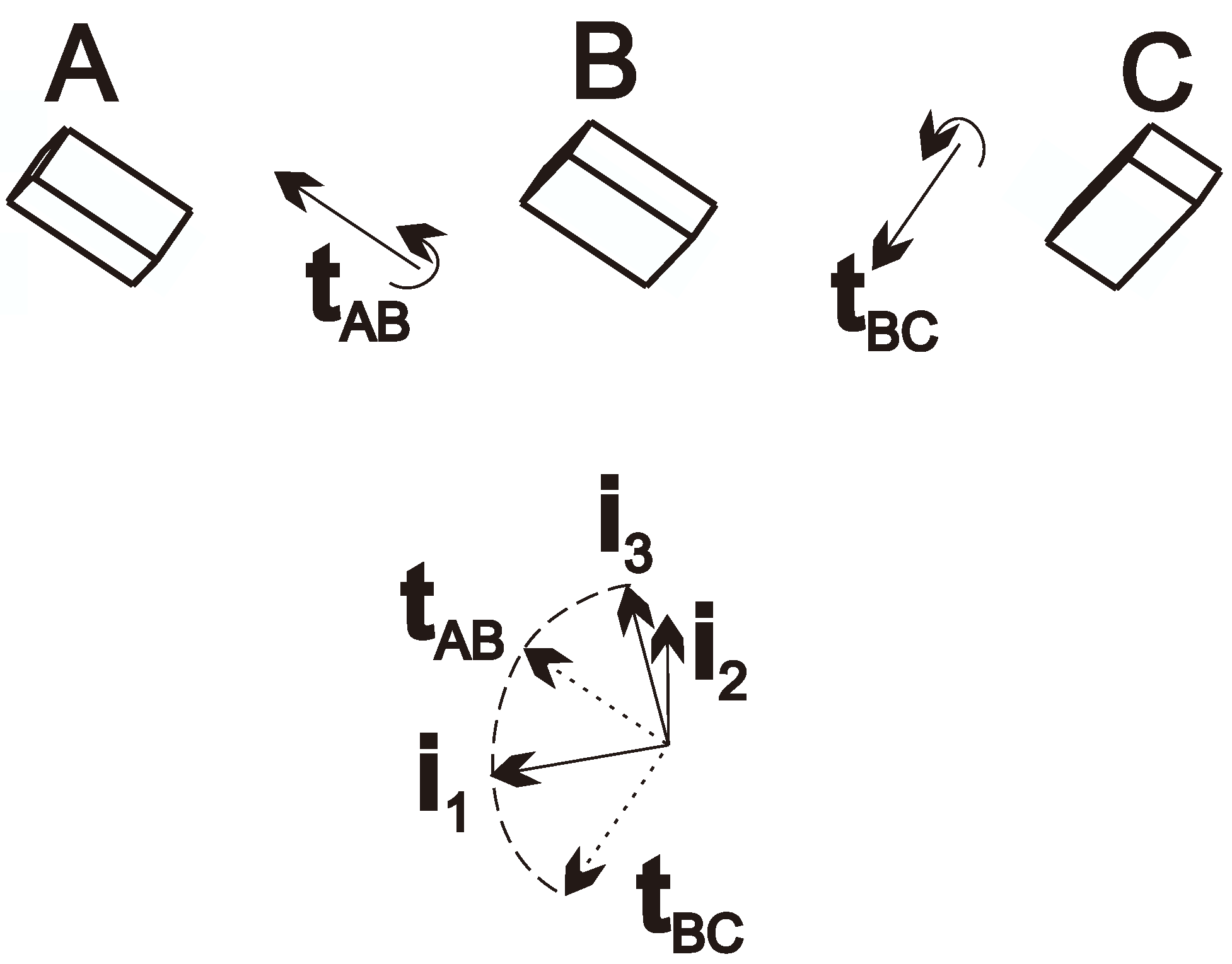
Consider the sensor pose at , and . The axis of rotation between two orientations gives a well-defined and easily obtainable common direction for both the sensor and the TCP.
For this, compute the direction of the axes as
if the computation results in a negative
angle, flip the direction of
. (The computation requires that
,
, and the angles of
and
be as close to the right angle as possible.) Furthermore, vectors
,
and
can be computed similarly.
Then, these values can be obtained by
and
frames as
Now the
and
directions are known by all frames; the following orthogonal directions can be defined based on them:
which constructs a frame denoted by
i. The method and the resulting frame are illustrated in
Figure 3.
Determining these base vectors from the vectors given by the
frame, the rotation matrix between the frames
and
i can be described as
It can also be computed for frames
,
and
as
,
and
.
Then, the initial guess for quaternions
and
can be computed as
3.2. Local Optimization
The previous step provided a good calibration for the three selected measurements. The local optimization step refines this calibration by taking into account all measurements for .
The correction of the orientations is defined with Roll–Pitch–Yaw variables (
)
where small angles are assumed due to the good initial guess.
With this correction term, the quaternions can be defined as
According to the parameters
and
, the measurements can be evaluated as
then the error of the measurement can be computed as the angle of a quaternion
where
Based on this derivation, this optimization problem can be written as
where a Nelder–Mead optimization can be used initialized from
,
.
From the resulting
,
vectors, the error of a measurement can be written as
4. Experimental Demonstration
This section presents examples of validating various orientation sensors using a UR16e manipulator [
24] with the proposed method. The results provide a straightforward comparison of the devices’ performance. We investigated two sensors, a MEMS-based IMU sensor and the HTC VIVE VR headset (Manufacturer: TDK INVENSENSE (San Jose, CA, USA) Type ID: ICM-20948) equipped with 6DoF tracking capabilities (so-called inside-out tracking).
4.1. ICM20948 IMU with Disabled Magnetometer
The IMU sensor ICM20948 [
25] used in the experiment integrates gyroscope, magnetometer, and accelerometer units in a single package. For this measurement, the magnetometer was turned off because of the disturbing magnetic field of the manipulator. It was found that the micro-vibrations of the manipulator can influence the performance of the sensor to a considerable extent causing noise and drift in the output signal. For this reason, the sensor was attached to the manipulator in silicon bedding instead of using a rigid mounting fixture.
Furthermore, the effect of these vibrations was also diminished by applying a higher robot speed (2–4 [cm]/step).
Figure 4 shows the path of the manipulator. After an initial motion phase, it performs five full circles. The figure also shows the orientation in each measurement point with red line segments in the
x direction and blue segments in the
z direction.
First, three measurements (samples recorded at , , and ) must be chosen as close to perpendicular as possible.
It was obtained by performing a search through the
section of the logged data, according to the following optimum criteria (see
Section 3.1):
where in optimal case
, so the angles are perpendicular.
On the initial phase of the path (), the procedure automatically looks for three measured orientations that are inclined at least 60 degrees and less than 120 degrees relative to each other (in this case, their indices were , and ). The angle differences between the orientations are and . Furthermore, the angle of and is because of the initial path segment, and is almost zero.
With the results of calibration, the
error of the orientation of the IMU sensor (considering the robot as a reference) can be computed, and it is plotted in
Figure 5 with blue. The histogram of the error is plotted in
Figure 6. They clearly show that the error is mostly below
, and by plotting the magnitude of rotations between the measurements (in red in
Figure 5), it is easy to see that significant errors are only measured during fast rotations. These errors are partially caused by the unavoidable time difference between signal processing in the robot and the sensors that result in a certain time delay between the parallel orientation samples.
It should be emphasized that the contribution of this paper is confined to the method and procedure for registering the robot’s and the orientation sensor’s references. Consequently, the investigation of the time delay is intentionally considered beyond the scope of this work. Measuring or identifying time delays in commercial systems (e.g., robot controllers; IMU’s internal signal processing, etc.), which are out of the researchers’ control, may not even be feasible in general. However, using the proposed procedure, a comparative delay analysis can be performed with multiple orientation sensors mounted on the robot simultaneously or consecutively. Such an analysis could be valuable from an engineering perspective when evaluating sensing technologies for specific applications.
4.2. HTC VIVE (IMU and SLAM Sensor-Fusion Using 6 Cameras)
The HTC VIVE Cosmos headset uses six cameras and an IMU unit for its SLAM algorithm and can be considered as a cutting-edge inside-out tracking technology. The headset was fixed to the flange of the manipulator and was moved on the path plotted in
Figure 4, without the initial segment. Because it was not sensitive to vibrations of slow robot motions, two rounds were recorded at different speeds.
In this case, an automatic search was also applied to obtain orientation samples with angles between them. The indices of the chosen measurements were , and , and the angles between them are and . Furthermore, the angle of and is , so in this case, .
After performing the calibration method described in
Section 3, the computation results in
errors plotted in
Figure 7 in blue and in the histogram of
Figure 8. The figures show that the error is mostly below
. The rotation angle between the measurements is also plotted in
Figure 7 with red, and it clearly shows that the larger differences between the sensors are measured only if the device is rotating.
4.3. Notes on the Robot Trajectory
The proposed method is designed to be robust to the robot’s motion during measurement, provided that the key poses required for calibration are carefully selected (See
Section 3). Specifically, the robot path must be planned to avoid kinematic singularities, as approaching these configurations can lead to large joint velocities, causing vibrations and potentially affecting the accuracy of orientation measurements.
Outside of these singularities, the robot’s path has no impact on the algorithm’s sensitivity, since the calibration process depends solely on the relative angular separation between the key poses. As long as these key poses are properly captured during the calibration phase and the relative orientation between the robot’s end-effector and the sensor is preserved, the method will maintain its reliability. By ensuring smooth, controlled robot motions and steering clear of singular configurations, the robustness of the proposed method can be upheld across various trajectories.


