
A Low-Profile, Triple-Band, and Wideband Antenna Using Dual-Band AMC


Abstract
:1. Introduction
2. Materials and Methods
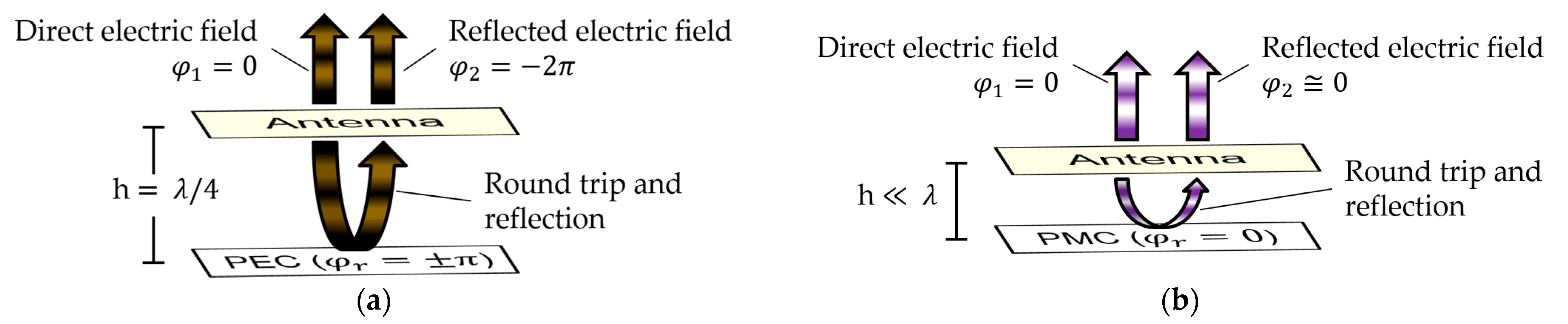
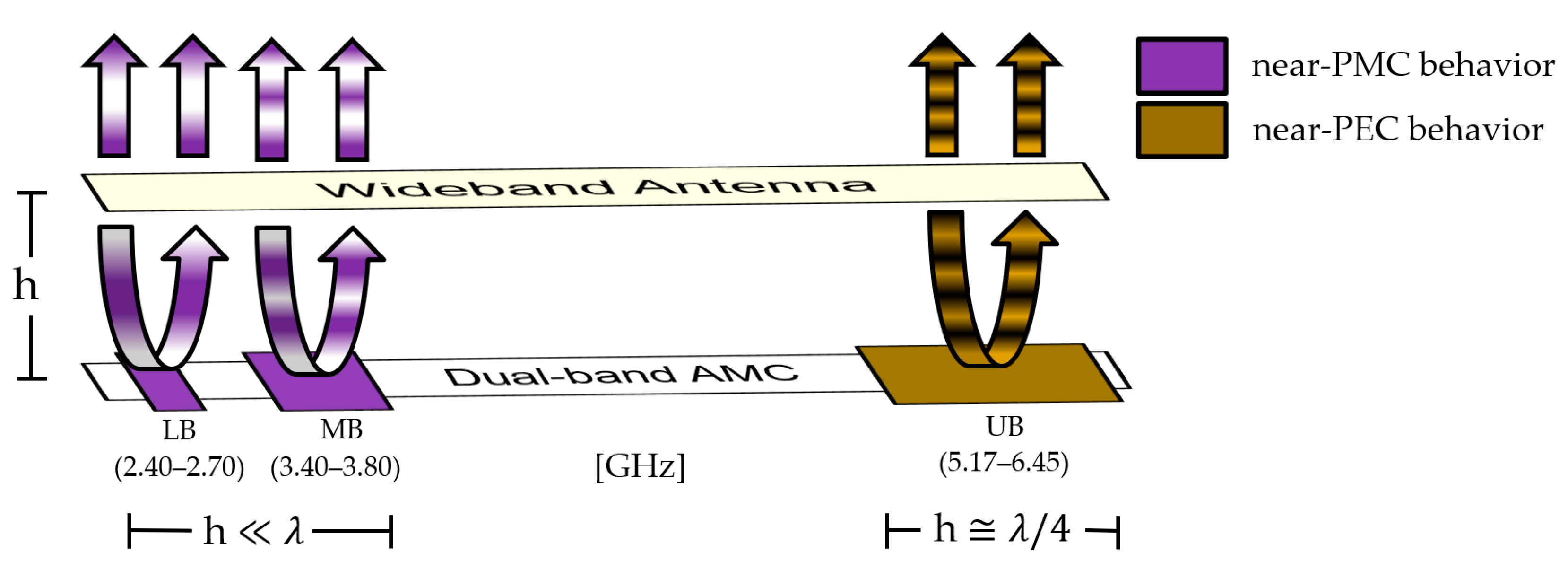
2.1. Working Principle
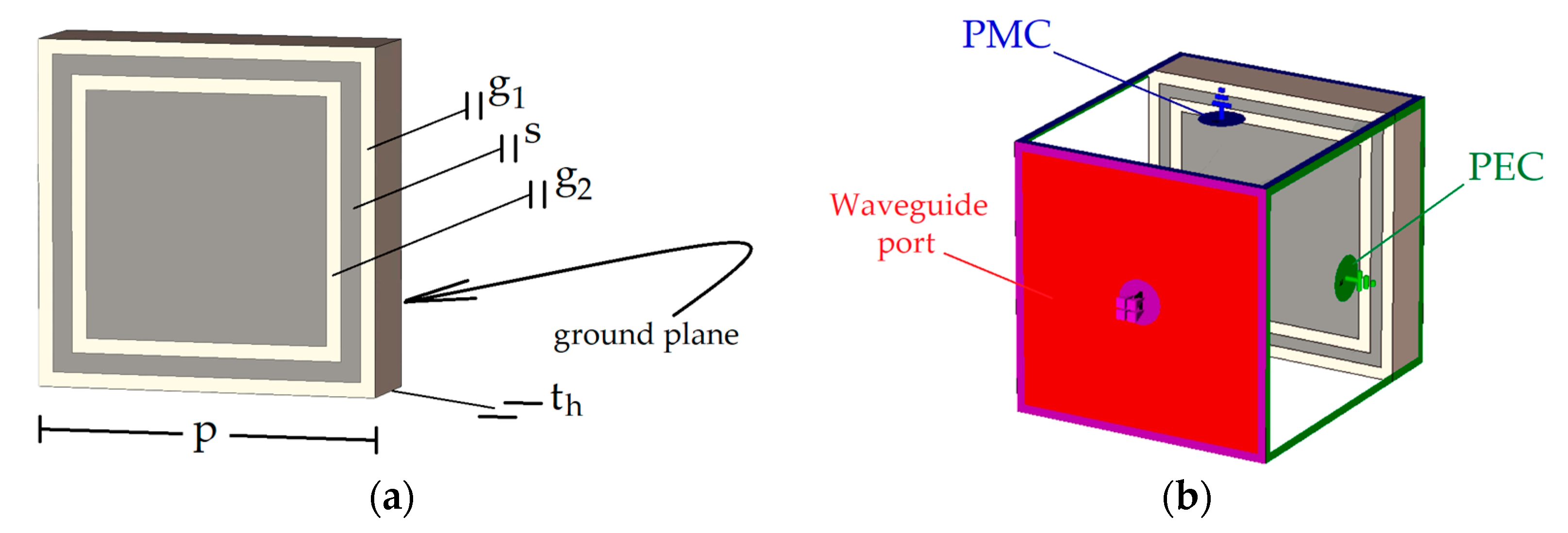
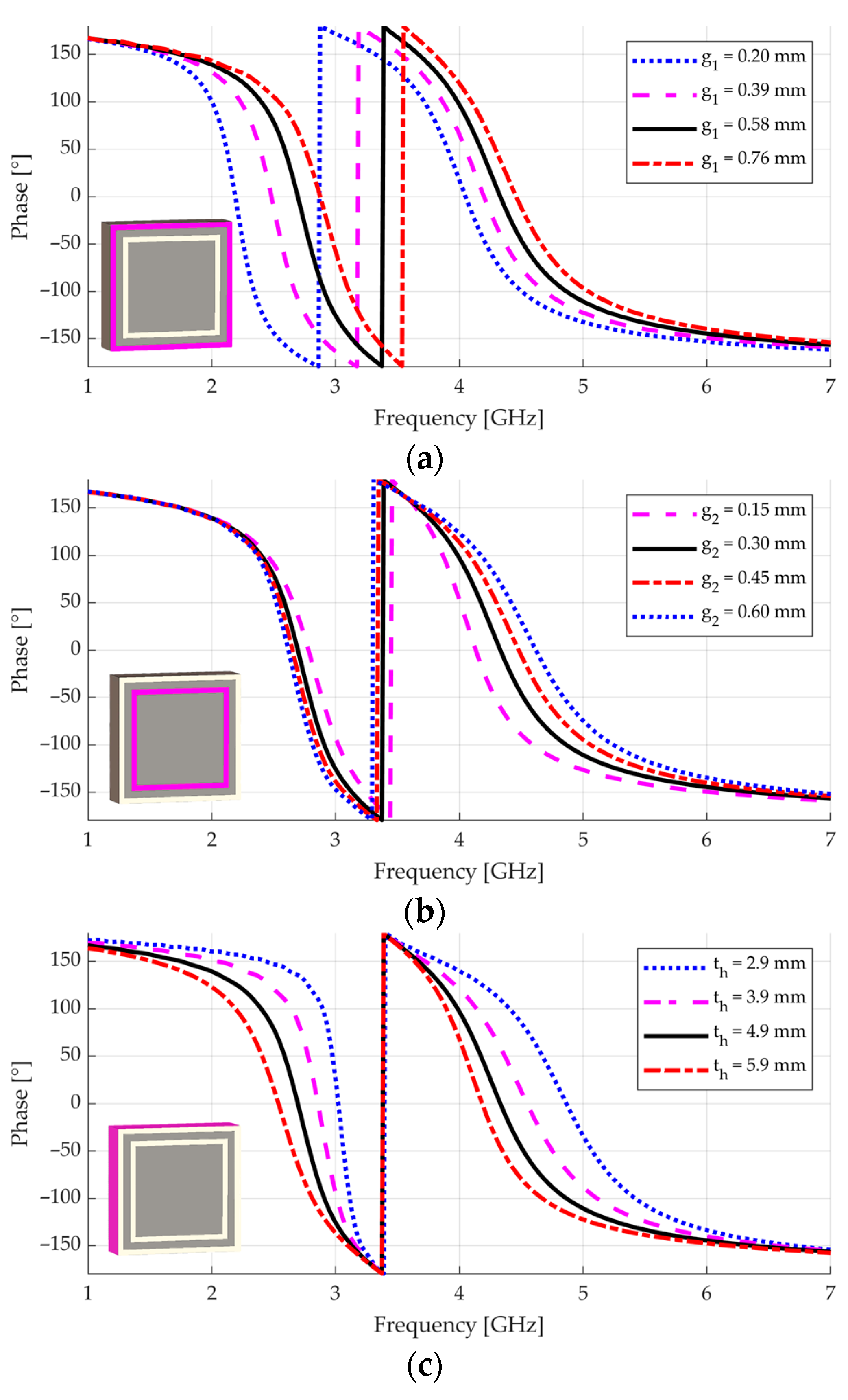
2.2. Choosing and Adjusting the Dual-Band AMC Unit Cell
- Consider changing the material to one that has a more appropriate relative permittivity if the second resonance is not close to the desired frequency;
- Consider changing the material to one that has another substrate thickness if the operational bandwidth achieved around the first resonance is not proper;
- Adjust the gap and the strip width to achieve the desired bandwidth around the second resonance;
- Adjust the periodicity to place the second resonance at the desired frequency;
- Adjust the gap to place the first resonance at the desired frequency; to achieve a fine adjustment in both resonance frequencies, some iterations between this and the previous step may be required.
2.3. Choosing and Adjusting the Radiating Element
2.4. Putting the AMC and the Radiating Element Together
- The AMC is in the antenna near-field region and is not illuminated by a plane wave;
- Some coupling effects between antenna and AMC may take place;
- The finitude of the AMC creates extra surface wave resonances [37].
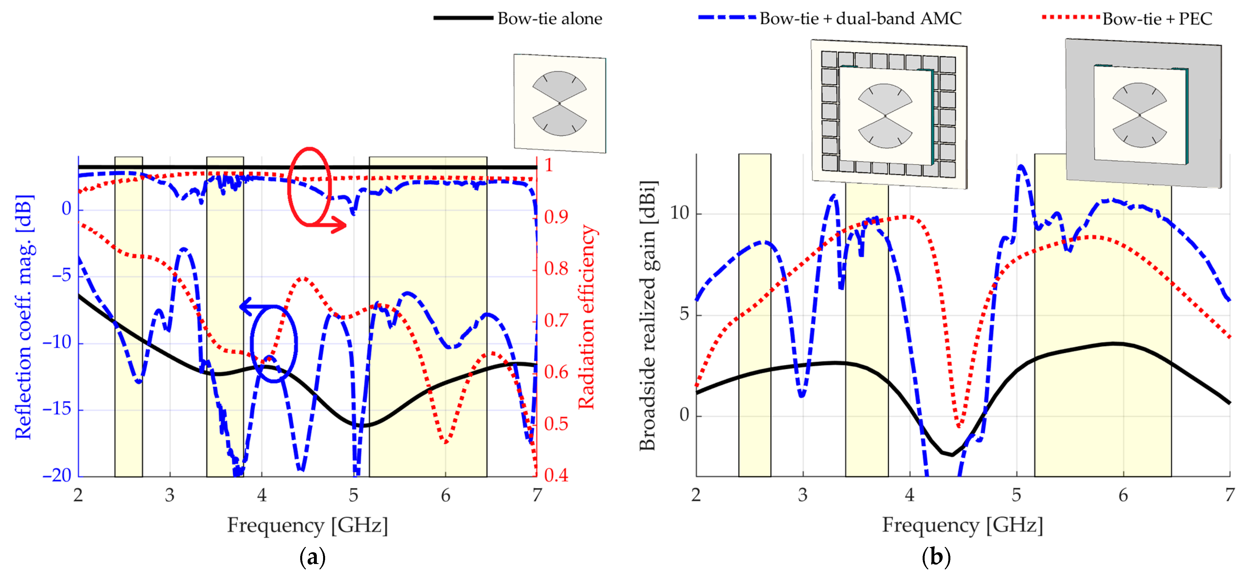
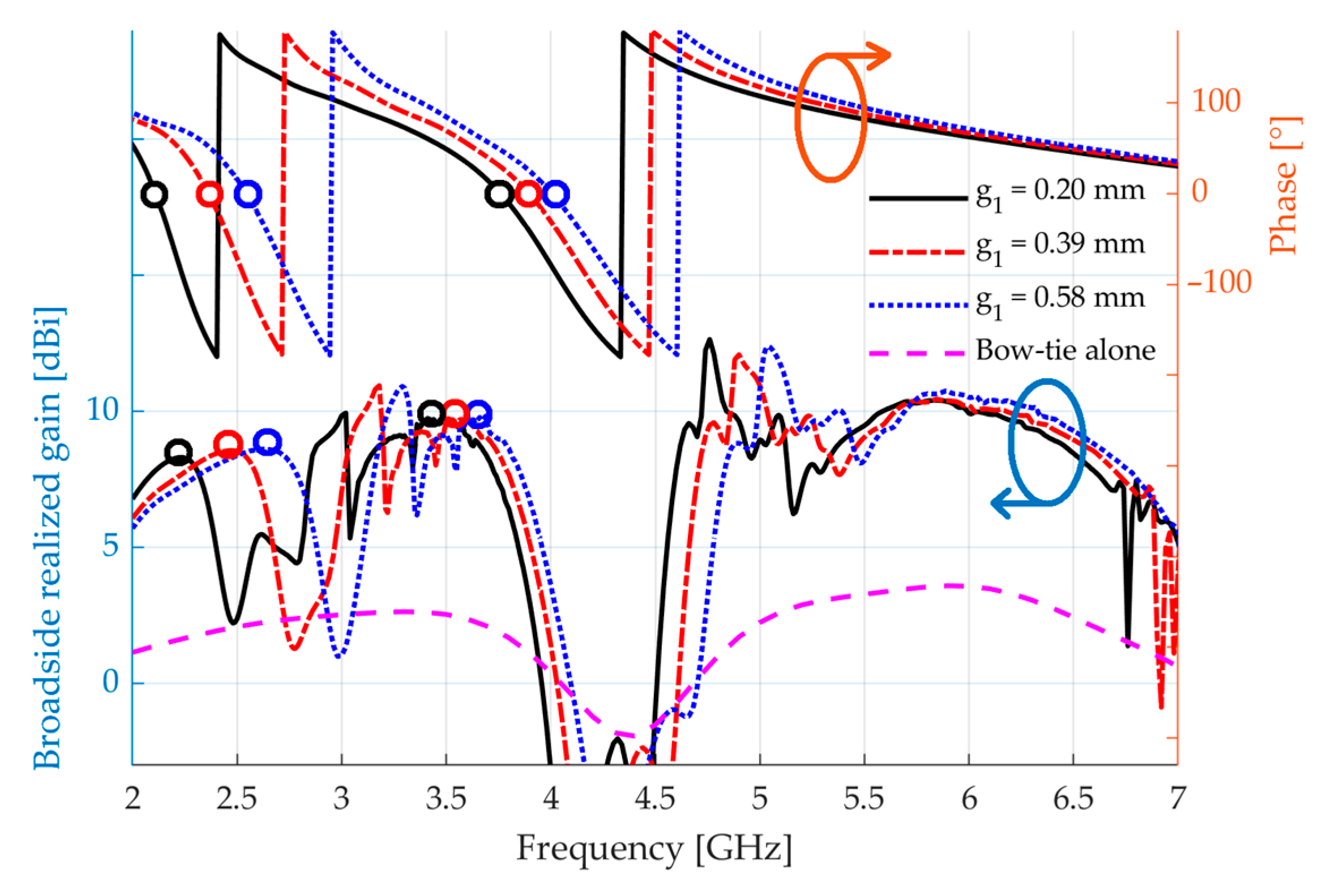
3. Results
4. Discussion
Author Contributions
Funding
Institutional Review Board Statement
Informed Consent Statement
Data Availability Statement
Conflicts of Interest
References
- Navarro-Ortiz, J.; Romero-Diaz, P.; Sendra, S.; Ameigeiras, P.; Ramos-Munoz, J.J.; Lopez-Soler, J.M. A Survey on 5G Usage Scenarios and Traffic Models. IEEE Commun. Surv. Tutor. 2020, 22, 905–929. [Google Scholar] [CrossRef]
- IEEE P802.11ax/D8.0; IEEE Approved Draft Standard for Information Technology—Telecommunications and Information Exchange between Systems Local and Metropolitan Area Networks—Specific Requirements Part 11: Wireless LAN Medium Access Control (MAC) and Physical Layer (PHY) Specifications Amendment 1: Enhancements for High Efficiency WLAN. IEEE: New York, NY, USA, 2021; pp. 1–820.
- Björnson, E.; Hoydis, J.; Sanguinetti, L. Massive MIMO Networks: Spectral, Energy, and Hardware Efficiency. Now Publishers Inc.: Boston, MA, USA, 2017. [Google Scholar]
- Djoma, C.; Jousset, M.; Lepage, A.C.; Mallégol, S.; Renard CBegaud, X. Maximal Bandwidth of an Archimedean Spiral Antenna Above a Reflector. IEEE Antennas Wirel. Propag. Lett. 2014, 13, 333–336. [Google Scholar] [CrossRef]
- Feresidis, A.P.; Goussetis, G.; Wang, S.; Vardaxoglou, J.C. Artificial magnetic conductor surfaces and their application to low-profile high-gain planar antennas. IEEE Trans. Antennas Propag. 2005, 53, 209–215. [Google Scholar] [CrossRef]
- Brewitt-Taylor, C.R. Limitation on the bandwidth of artificial perfect magnetic conductor surfaces. IET Microw. Antennas Propag. 2007, 1, 255–260. [Google Scholar] [CrossRef]
- Yang, W.; Hua, G.; Hong, W. Wideband artificial magnetic conductor structure for Ku-band antenna applications. In Proceedings of the 2009 3rd IEEE International Symposium on Microwave, Antenna, Propagation and EMC Technologies for Wireless Communications, Beijing, China, 27 October 2009. [Google Scholar] [CrossRef]
- Cheng, Y.-F.; Zhao, Y.; Peng, F.; Liao, C. Wideband AMC-Based Phased Array with Enhanced Bandwidth and Wide-Angle Scan. In Proceedings of the 3rd IEEE International Conference on Microwave and Millimeter Wave Technology (ICMMT), Shanghai, China, 20 September 2020. [Google Scholar] [CrossRef]
- Wang, Z.; Jiao, Y.; Zhang, Y.; Wen, J.; Zhao, G. Wideband AMC Surface and Applications to Low Profile Circularly Polarized Slot Antennas. In Proceedings of the 2019 International Conference on Microwave and Millimeter Wave Technology (ICMMT), Guangzhou, China, 19 May 2019. [Google Scholar] [CrossRef]
- Damaj, L.; Lepage, A.C.; Begaud, X. Low profile, directive and very wideband antenna on a high impedance surface. In Proceedings of the 4th European Conference on Antennas and Propagation, Barcelona, Spain, 12 April 2010. [Google Scholar]
- Akhoondzadeh-Asl, L.; Nourinia, J.; Ghobadi, C.; Hall, P.S. Influence of Element Shape on the Bandwidth of Artificial Magnetic Conductors. J. Electromagn. Waves Appl. 2007, 21, 929–946. [Google Scholar] [CrossRef]
- Monorchio, A.; Manara, G.; Lanuzza, L. Synthesis of artificial magnetic conductors by using multilayered frequency selective surfaces. IEEE Antennas Wirel. Propag. Lett. 2002, 1, 196–199. [Google Scholar] [CrossRef]
- Rayno, J.T.; Nakatsu JS, K.; Huang, G.C.; Celik, N.; Iskander, M.F. 3D metamaterial broadband ground plane designed using genetic programming for the long slot array antenna. In Proceedings of the 2013 IEEE Antennas and Propagation Society International Symposium (APSURSI), Orlando, FL, USA, 7 July 2013. [Google Scholar] [CrossRef]
- Rayno, J.; Iskander, M.F.; Celik, N. Synthesis of Broadband True-3D Metamaterial Artificial Magnetic Conductor Ground Planes Using Genetic Programming. IEEE Trans. Antennas Propag. 2014, 62, 5732–5744. [Google Scholar] [CrossRef]
- Kern, D.J.; Werner, D.H.; Monorchio, A.; Lanuzza, L.; Wilhelm, M.J. The design synthesis of multiband artificial magnetic conductors using high impedance frequency selective surfaces. IEEE Trans. Antennas Propag. 2005, 53, 8–17. [Google Scholar] [CrossRef]
- Alwareth, H.; Ibrahim, I.M.; Zakaria, Z.; Al-Gburi, A.J.A.; Ahmed, S.; Nasser, Z.A. A Wideband High-Gain Microstrip Array Antenna Integrated with Frequency-Selective Surface for Sub-6 GHz 5G Applications. Micromachines 2022, 13, 1215. [Google Scholar] [CrossRef]
- Al-Gburi, A.J.A.; Ibrahim, I.M.; Zakaria, Z.; Abdulhameed, M.K.; Saeidi, T. Enhancing Gain for UWB Antennas Using FSS: A Systematic Review. Mathematics 2021, 9, 3301. [Google Scholar] [CrossRef]
- Shi, C.; Zou, J.; Gao, J.; Liu, C. Gain Enhancement of a Dual-Band Antenna with the FSS. Electronics 2022, 11, 2882. [Google Scholar] [CrossRef]
- Zhang, Y.; Zhang, X.Y.; Ye, L.; Pan, Y. Dual-Band Base Station Array Using Filtering Antenna Elements for Mutual Coupling Suppression. IEEE Trans. Antennas Propag. 2016, 8, 3423–3430. [Google Scholar] [CrossRef]
- An, W.X.; Wong, H.; Lau, K.L.; Li, S.F.; Xue, Q. Design of Broadband Dual-Band Dipole for Base Station Antenna. IEEE Trans. Antennas Propag. 2012, 3, 1592–1595. [Google Scholar] [CrossRef]
- Cui, Y.; Li, R.; Wang, P. Novel Dual-Broadband Planar Antenna and Its Array for 2G/3G/LTE Base Stations. IEEE Trans. Antennas Propag. 2013, 3, 1132–1139. [Google Scholar] [CrossRef]
- Zhu, X.; Zhang, J.; Cui, T.; Zheng, Z. A Dielectric-Loaded Dual-Broadband Printed Dipole Antenna With Stable Radiation Pattern in the H-Plane. IEEE Antennas Wirel. Propag. Lett. 2019, 9, 1761–1765. [Google Scholar] [CrossRef]
- Yang, G.; Zhang, S.; Li, J.; Zhang, Y.; Pedersen, G.F. A Multi-Band Magneto-Electric Dipole Antenna With Wide Beam-Width. IEEE Access 2020, 8, 68820–68827. [Google Scholar] [CrossRef]
- Feng, B.; Lai, J.; Zeng, Q.; Chung, K.L. A Dual-Wideband and High Gain Magneto-Electric Dipole Antenna and Its 3D MIMO System With Metasurface for 5G/WiMAX/WLAN/X-Band Applications. IEEE Access 2018, 6, 33387–33398. [Google Scholar] [CrossRef]
- Hua, Q.; Huang, Y.; Song, C.; Akinsolu, M.O.; Liu, B.; Jia, T.; Xu, Q.; Alieldin, A. A Novel Compact Quadruple-Band Indoor Base Station Antenna for 2G/3G/4G/5G Systems. IEEE Access 2019, 7, 151350–151358. [Google Scholar] [CrossRef]
- Abbasi, N.A.; Langley, R.J. Multiband-integrated antenna/artificial magnetic conductor. IET Microw. Antennas Propag. 2011, 5, 711–717. [Google Scholar] [CrossRef]
- Mouhouche, F.; Azrar, A.; Dehmas, M.; Djafer, K. Gain Enhancement of Monopole Antenna using AMC Surface. Adv. Electromagn. 2018, 3, 69–74. [Google Scholar] [CrossRef]
- Paracha, K.N.; Abdul Rahim, S.K.; Soh, P.; Chatha, H.T.; Misran, M.H.; Lokman, A.H. A dual band stub-loaded AMC design for the gain enhancement of a planar monopole antenna. Microw. Opt. Technol. Lett. 2018, 60, 2108–2112. [Google Scholar] [CrossRef]
- Liu, Q.; Liu, H.; He, W.; He, S. A Low-Profile Dual-Band Dual-Polarized Antenna With an AMC Reflector for 5G Communications. IEEE Access 2020, 8, 24072–24080. [Google Scholar] [CrossRef]
- Zhai, H.; Zhang, K.; Yang, S.; Feng, D. A Low-Profile Dual-Band Dual-Polarized Antenna With an AMC Surface for WLAN Applications. IEEE Antennas Wirel. Propag. Lett. 2017, 16, 2692–2695. [Google Scholar] [CrossRef]
- Hu, T.; Pan, Z.; Saitou, M.; Liu, J.; Shimamoto, S. A triple-band antenna loaded with reflector surface for WLAN and 5G applications. J. Commun. 2020, 15, 729–734. [Google Scholar] [CrossRef]
- Mantash, M.; Tarot, A. On the bandwidth and geometry of dual-band AMC structures. In Proceedings of the 10th European Conference on Antennas and Propagation (EuCAP), Davos, Switzerland, 10 April 2016. [Google Scholar] [CrossRef]
- Linot, F.; Cousin, R.; Begaud, X.; Soiron, M. Design and measurement of High Impedance Surface. In Proceedings of the 4th European Conference on Antennas and Propagation, Barcelona, Spain, 12 April 2010. [Google Scholar]
- Compton, R.; McPhedran, R.; Popovic, Z.; Rebeiz, G.; Tong, P.; Rutledge, D. Bow-tie antennas on a dielectric half-space: Theory and experiment. IEEE Trans. Antennas Propag. 1987, 6, 622–631. [Google Scholar] [CrossRef]
- Gonçalves Licursi de Mello, R.; Lepage, A.C.; Begaud, X. The bow-tie antenna: Performance limitations and improvements. IET Microw. Antennas Propag. 2022, 16, 283–294. [Google Scholar] [CrossRef]
- Rutledge, D.E.; Schwarz, S.E.; Adams, A.T. Infrared and submillimetre antennas. Infrared Phys. 1978, 18, 713–729. [Google Scholar] [CrossRef]
- Costa, F.; Luukkonen, O.; Simovski, C.R.; Monorchio, A.; Tretyakov, S.A.; de Maagt, P.M. TE Surface Wave Resonances on High-Impedance Surface Based Antennas: Analysis and Modeling. IEEE Trans. Antennas Propag. 2011, 10, 3588–3596. [Google Scholar] [CrossRef]
- Vahdani, M.; Begaud, X. A directive ultra wideband sinuous slot antenna. In Proceedings of the First European Conference on Antennas and Propagation, Nice, France, 6 November 2006. [Google Scholar] [CrossRef]
- Tran, H.H.; Park, I. A Dual-Wideband Circularly Polarized Antenna Using an Artificial Magnetic Conductor. IEEE Antennas Wirel. Propag. Lett. 2015, 15, 950–953. [Google Scholar] [CrossRef]


| Symbol | Description | Value |
|---|---|---|
| substrate relative permittivity | ||
| substrate loss tangent | ||
| outer gap | ||
| inner gap | ||
| strip between gaps | ||
| periodicity | ||
| substrate thickness |
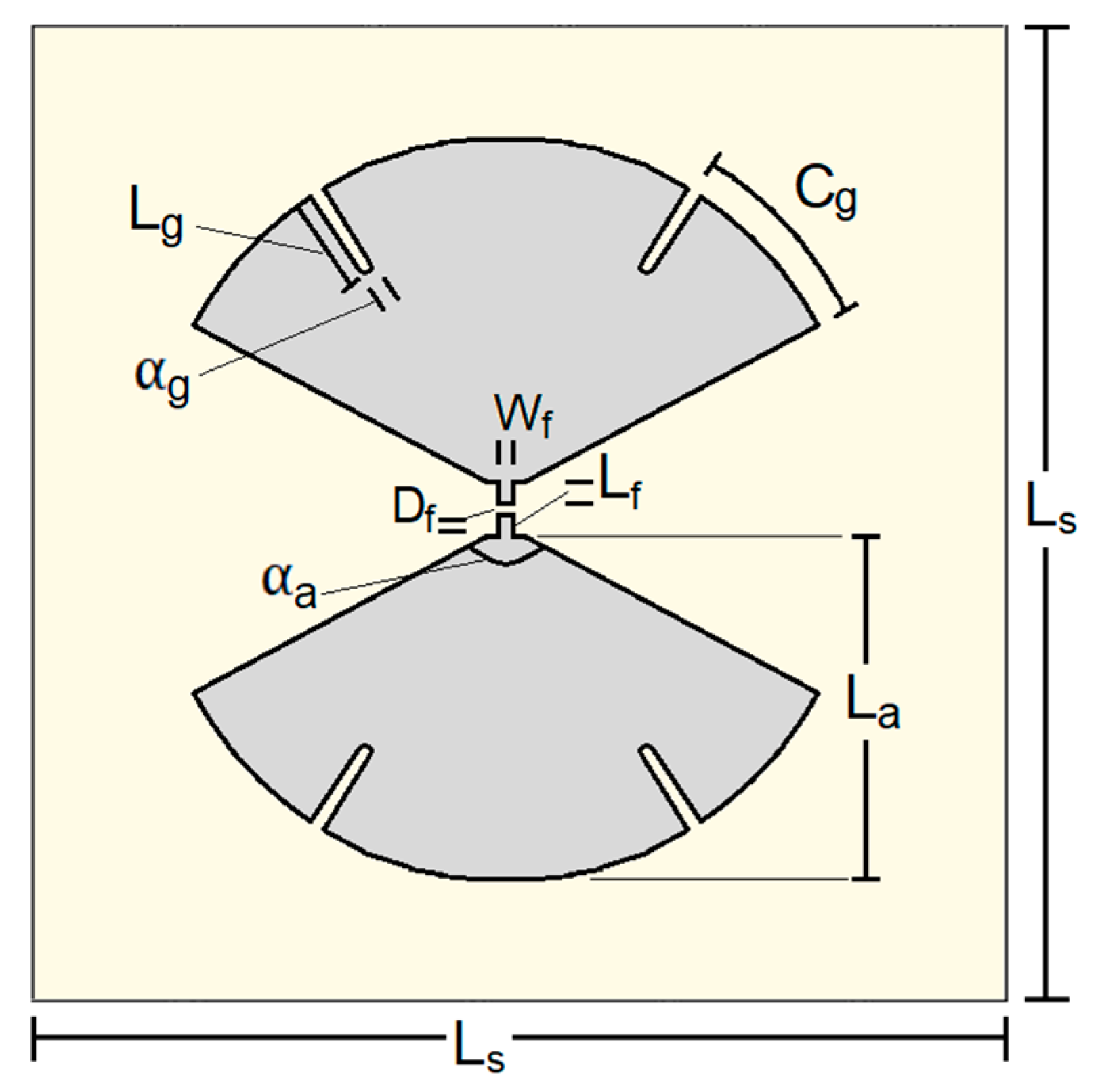
| Symbol | Description | Value |
|---|---|---|
| substrate relative permittivity | 2.2 | |
| substrate loss tangent | 0.0009 | |
| substrate length | 94.5 mm | |
| substrate thickness | 0.76 mm | |
| bow length | 31.5 mm | |
| bow flare angle | 124.4° | |
| feeding strip length | 0.80 mm | |
| feeding strip width | 0.60 mm | |
| gap between feeding strips | 0.76 mm | |
| groove length | 7.0 mm | |
| groove angular width | 0.69° | |
| groove angular position | 30.0° |
| Work | 3-dB Gain Bandwidth | Number of Sources | Where the Complexity Is | |||
|---|---|---|---|---|---|---|
| [23] | 4 | source | ||||
| – | – | |||||
| – | – | |||||
| – | – | |||||
| [25] | 2 | source, feeding and parasitic elements | – | |||
| – | – | |||||
| – | – | |||||
| – | – | |||||
| [26] | 1 | reflector | (peak) | |||
| – | – | |||||
| – | (peak) | |||||
| – | – | |||||
| [28] | – | 1 | reflector | (peak) | ||
| (peak) | ||||||
| (peak) | ||||||
| [31] | – | 1 | reflector | – | ||
| – | – | |||||
| – | – | |||||
| This work | – | 1 | reflector | – | ||
| – | – | |||||
| – | – |
Disclaimer/Publisher’s Note: The statements, opinions and data contained in all publications are solely those of the individual author(s) and contributor(s) and not of MDPI and/or the editor(s). MDPI and/or the editor(s) disclaim responsibility for any injury to people or property resulting from any ideas, methods, instructions or products referred to in the content. |
© 2023 by the authors. Licensee MDPI, Basel, Switzerland. This article is an open access article distributed under the terms and conditions of the Creative Commons Attribution (CC BY) license (https://creativecommons.org/licenses/by/4.0/).
Share and Cite
Gonçalves Licursi de Mello, R.; Lepage, A.C.; Begaud, X. A Low-Profile, Triple-Band, and Wideband Antenna Using Dual-Band AMC. Sensors 2023, 23, 1920. https://doi.org/10.3390/s23041920
Gonçalves Licursi de Mello R, Lepage AC, Begaud X. A Low-Profile, Triple-Band, and Wideband Antenna Using Dual-Band AMC. Sensors. 2023; 23(4):1920. https://doi.org/10.3390/s23041920
Chicago/Turabian StyleGonçalves Licursi de Mello, Rafael, Anne Claire Lepage, and Xavier Begaud. 2023. "A Low-Profile, Triple-Band, and Wideband Antenna Using Dual-Band AMC" Sensors 23, no. 4: 1920. https://doi.org/10.3390/s23041920
APA StyleGonçalves Licursi de Mello, R., Lepage, A. C., & Begaud, X. (2023). A Low-Profile, Triple-Band, and Wideband Antenna Using Dual-Band AMC. Sensors, 23(4), 1920. https://doi.org/10.3390/s23041920