
Dual-Channel Stretchable, Self-Tuning, Liquid Metal Coils and Their Fabrication Techniques

 , , , ,
Abstract
:1. Introduction
2. Materials and Methods
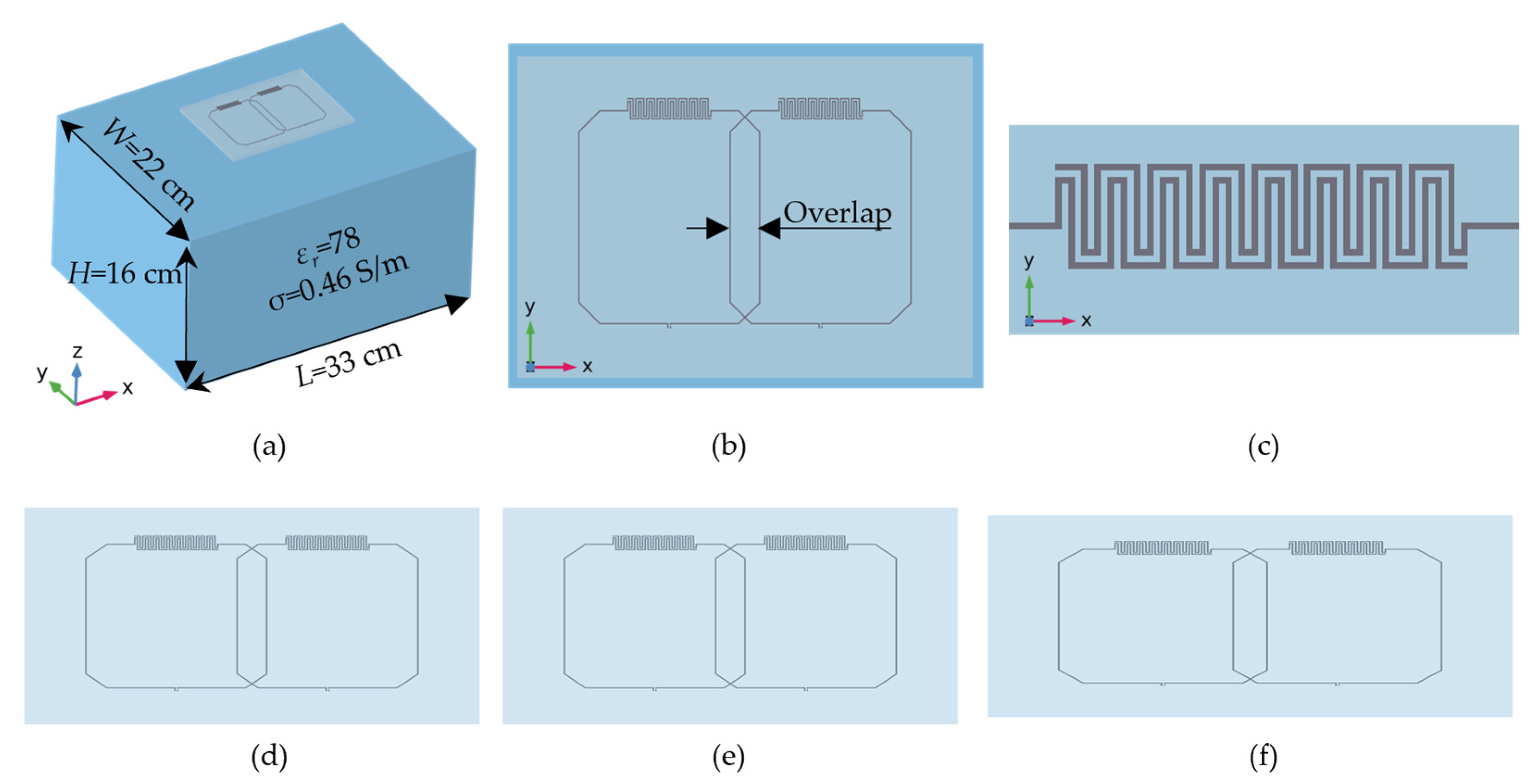
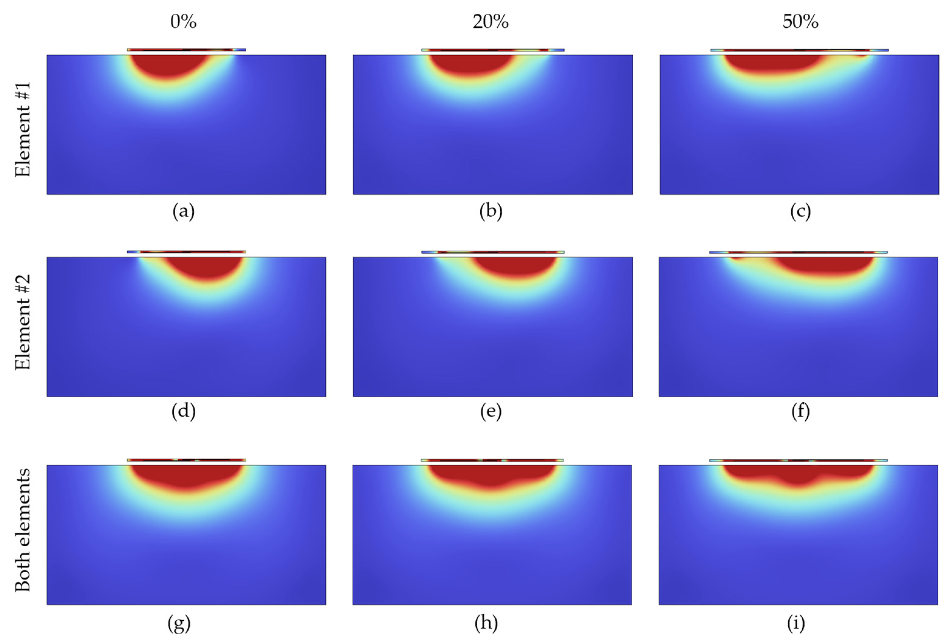
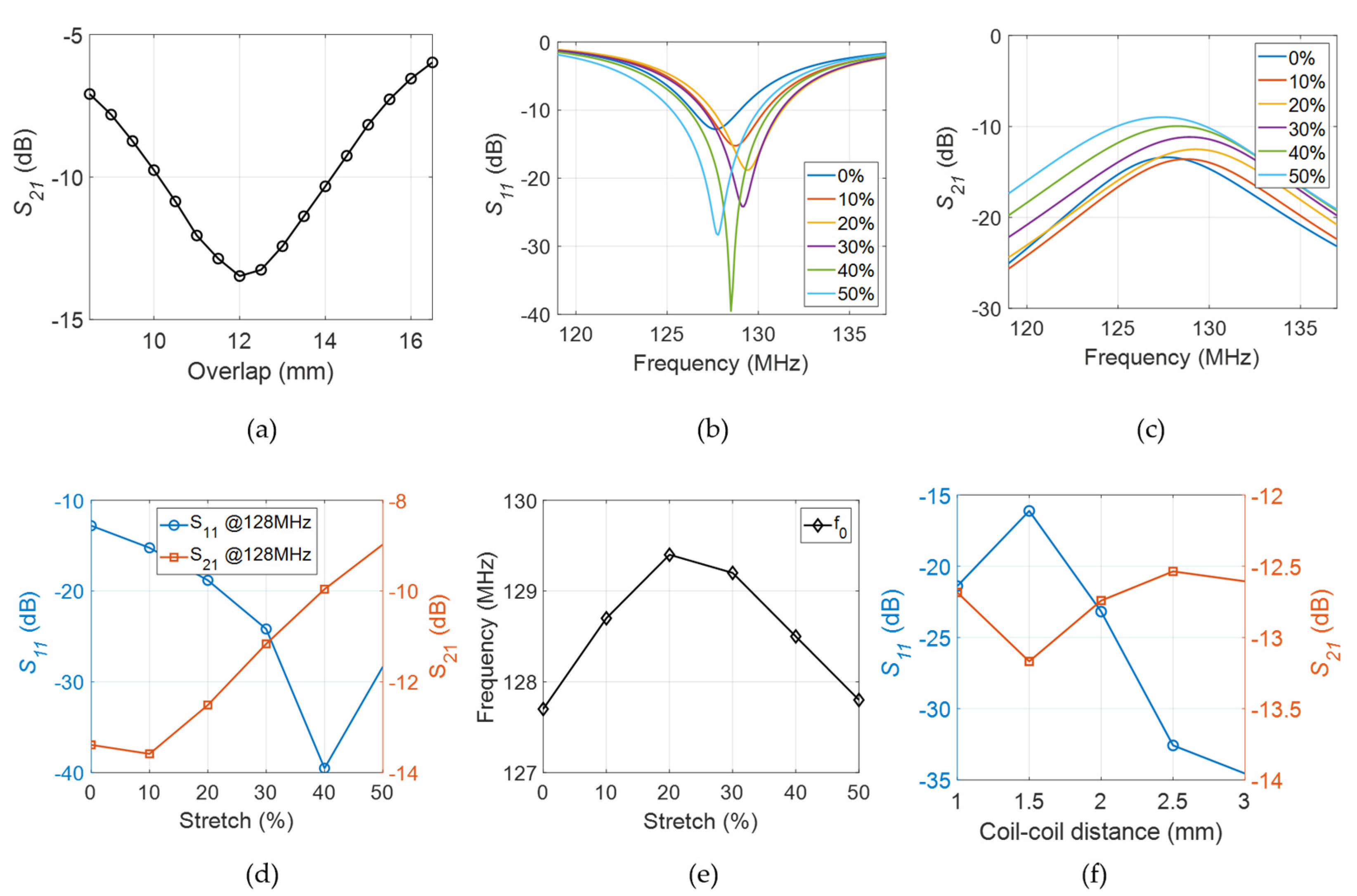
2.1. Simulations
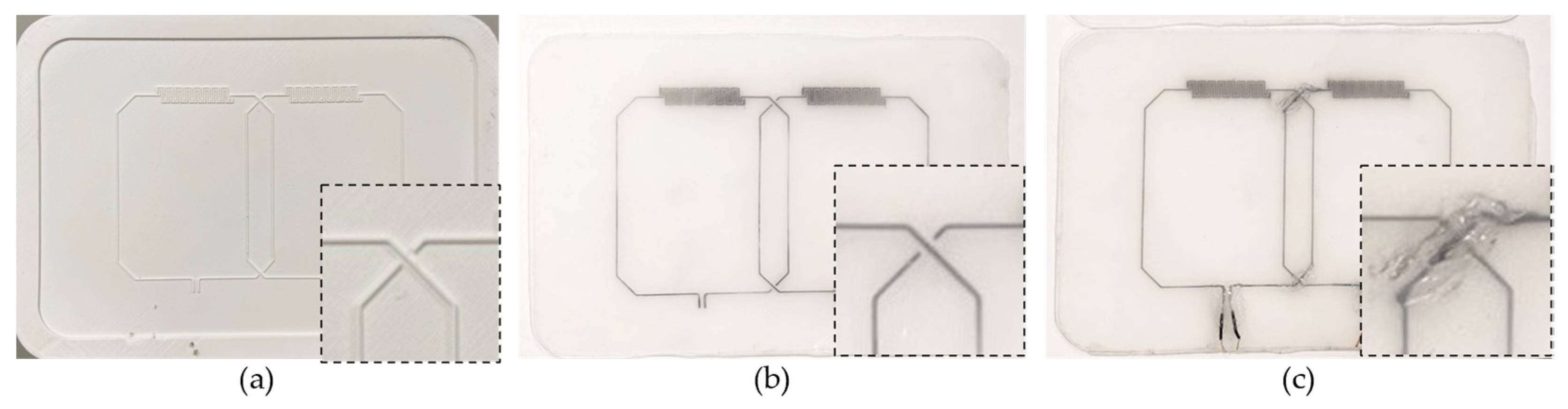
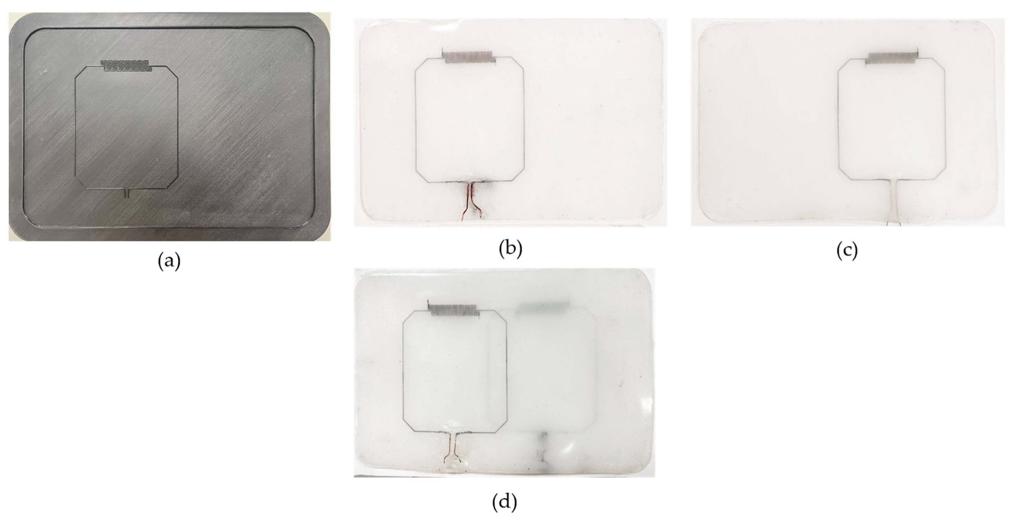
2.2. Fabrication Techniques
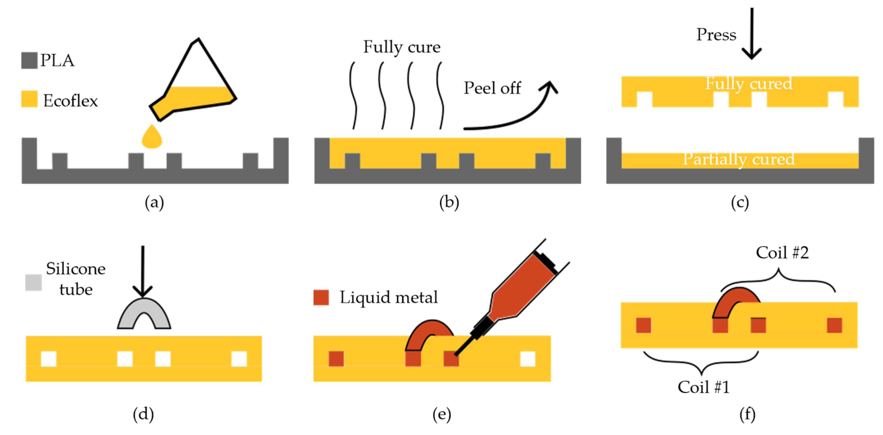
2.2.1. Single Layer Casting
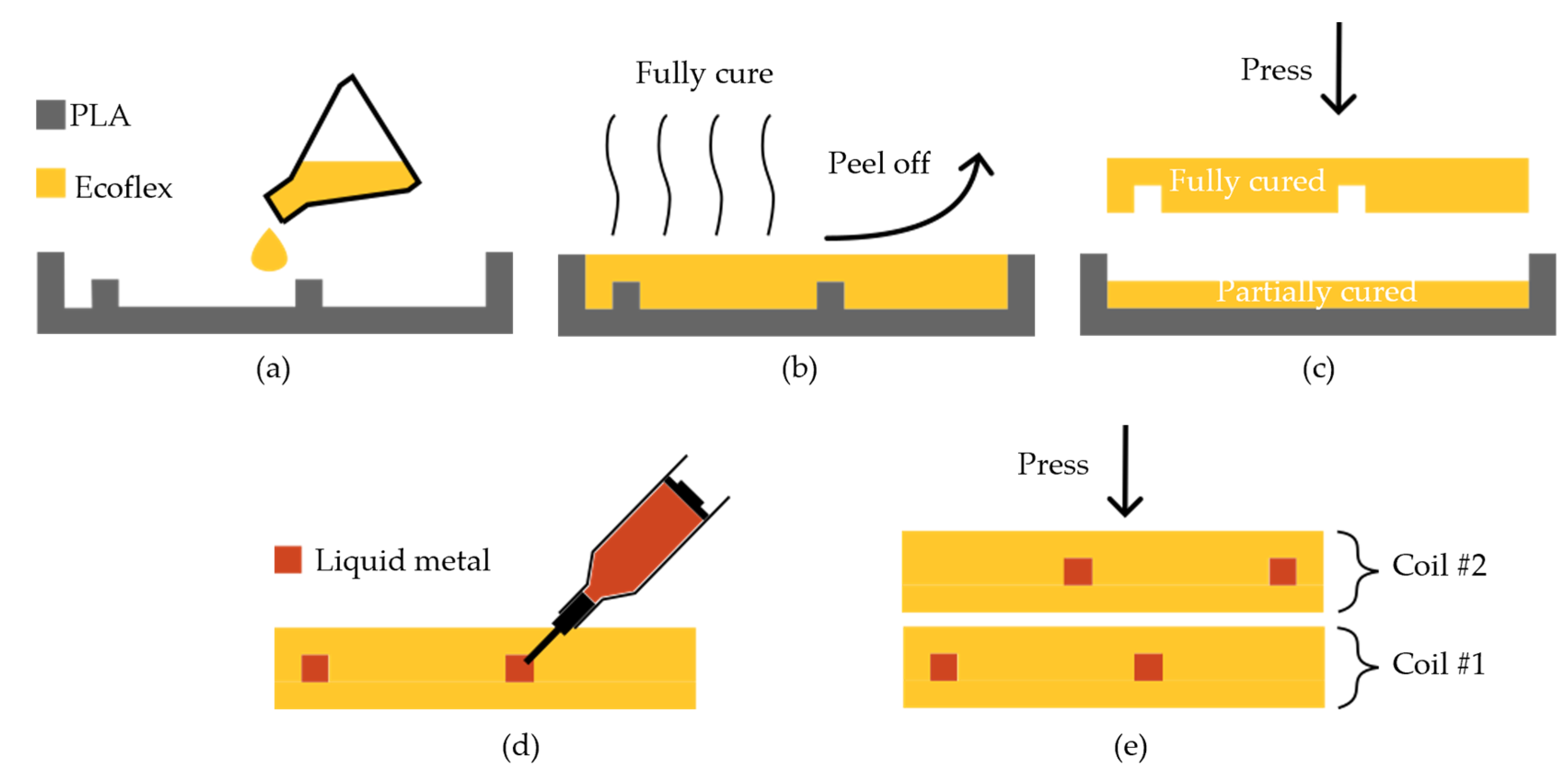
2.2.2. Double Layer Casting
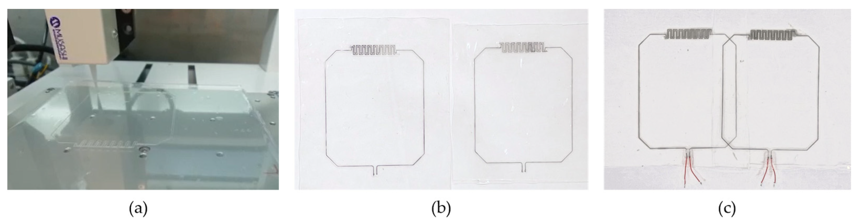
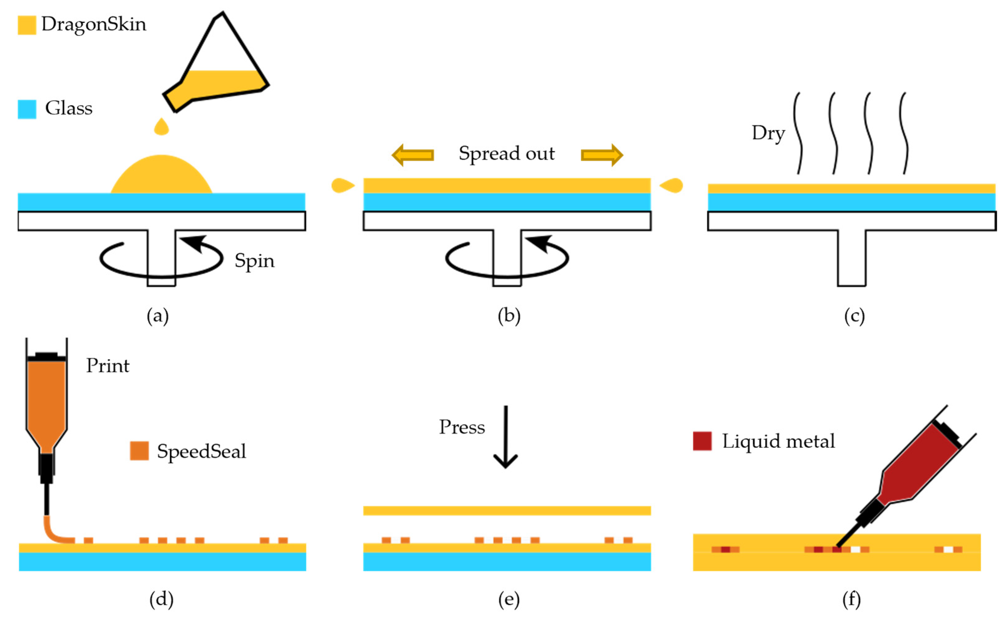
2.2.3. Direct Ink Writing
2.2.4. Conductors and Circuitry
2.3. Benchtop Measurements
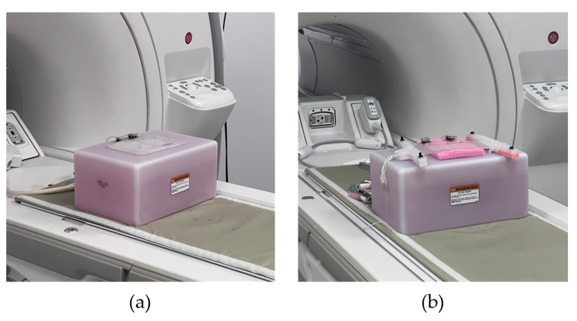
2.4. In Vitro Imaging
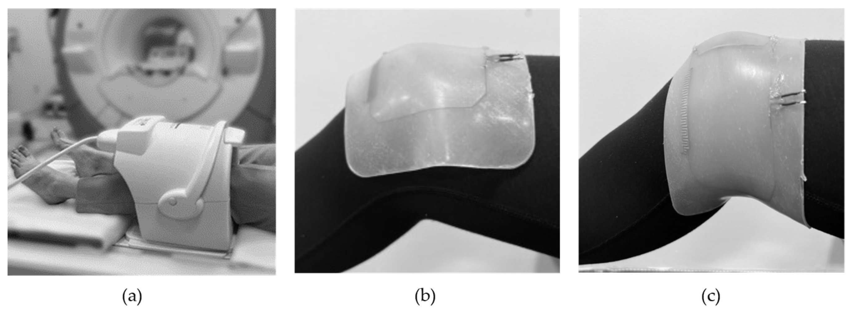
2.5. In Vivo Imaging
3. Results
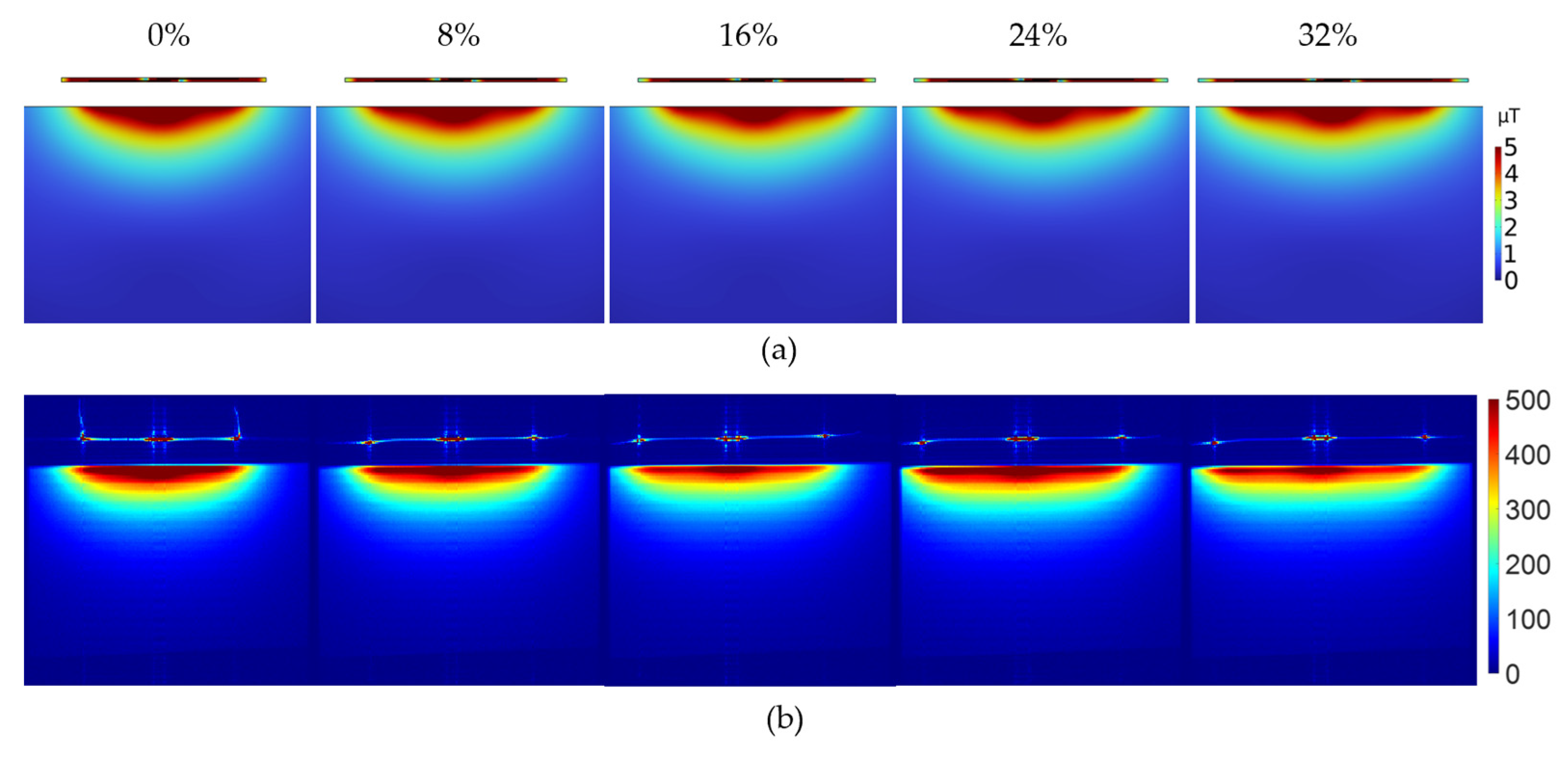
3.1. Simulations
3.2. Fabrication
3.2.1. Single Layer Casting
3.2.2. Double Layer Casting
3.2.3. Direct Ink Writing
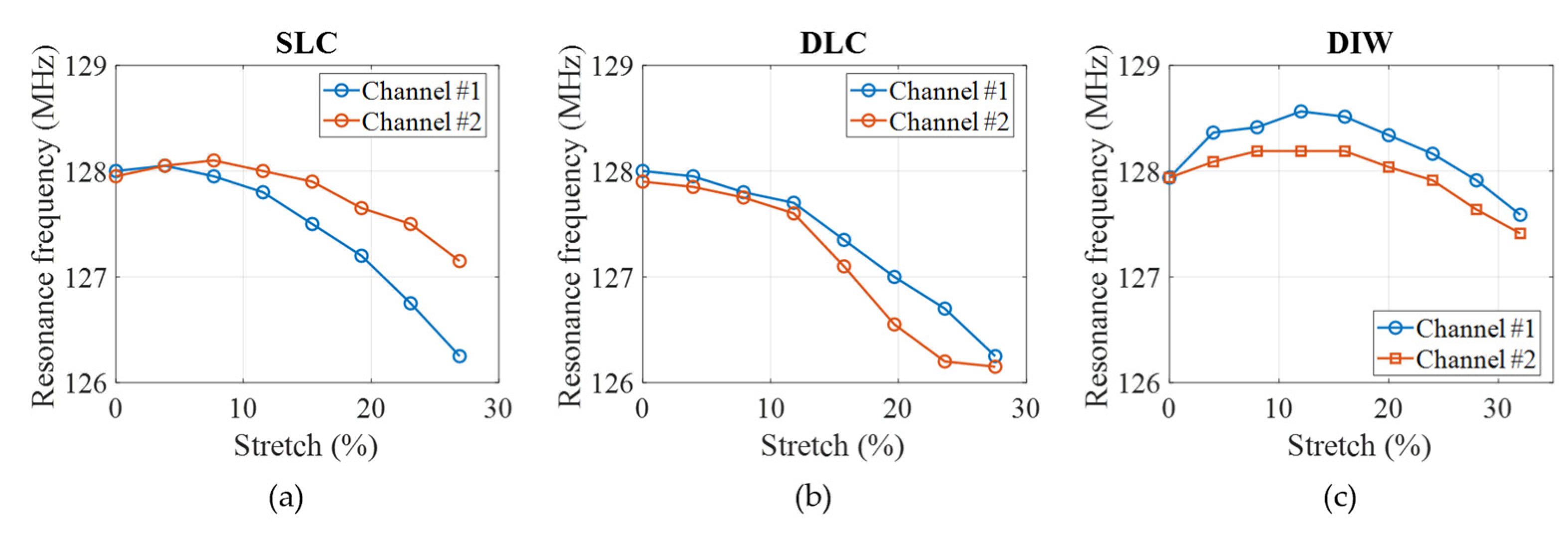
3.3. Benchtop Measurements
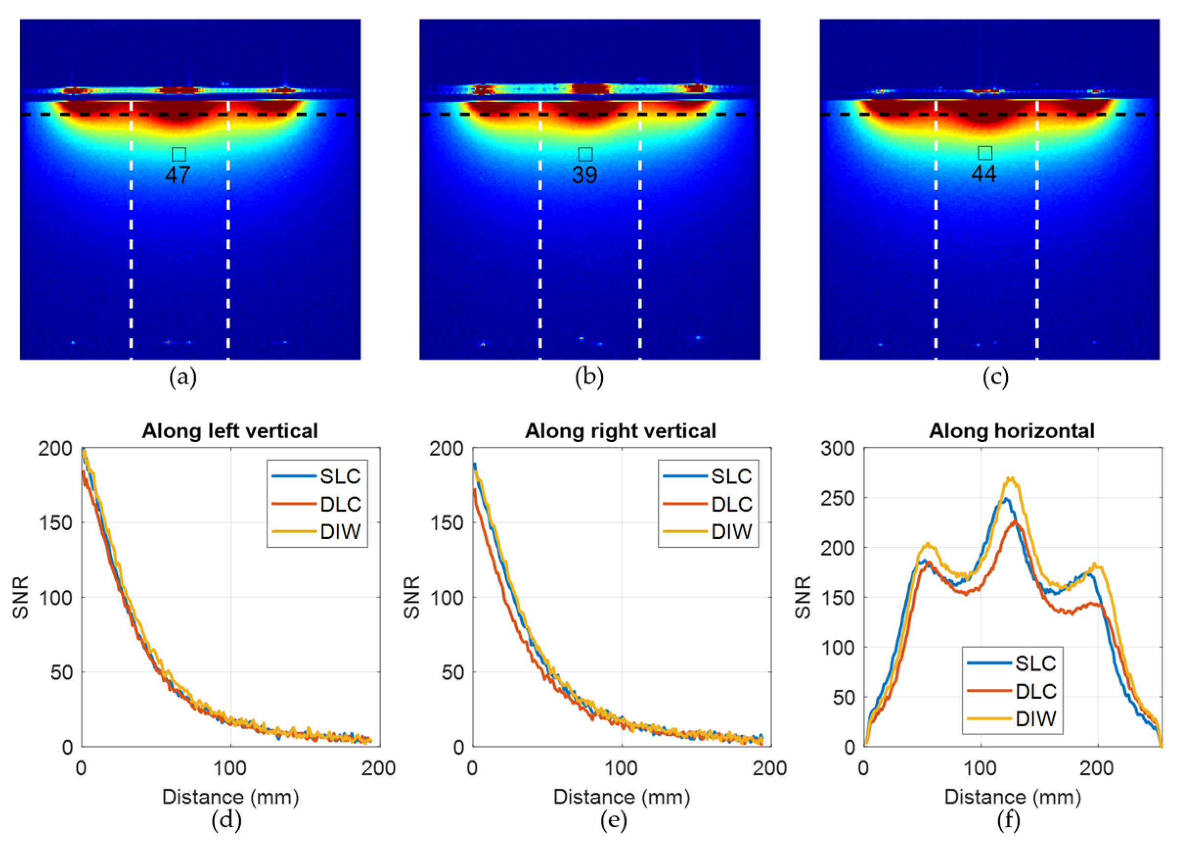
3.4. In Vitro Imaging
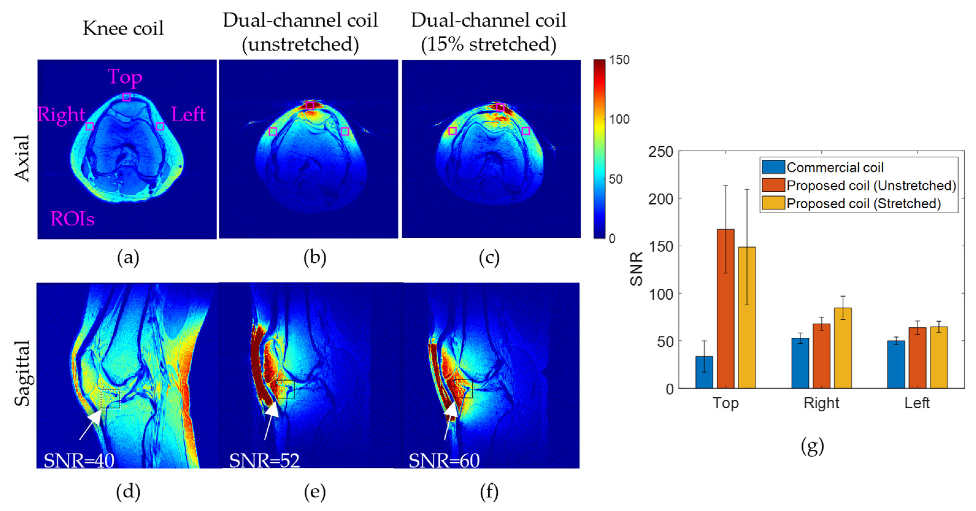
3.5. In Vivo Imaging
4. Discussion
5. Conclusions
Author Contributions
Funding
Institutional Review Board Statement
Informed Consent Statement
Data Availability Statement
Acknowledgments
Conflicts of Interest
References
- Vaughan, J.T.; Griffiths, J.R. RF Coils for MRI; John Wiley & Sons: Hoboken, NJ, USA, 2012. [Google Scholar]
- Kumar, A.; Edelstein, W.A.; Bottomley, P.A. Noise figure limits for circular loop MR coils. Magn. Reson. Med. 2009, 61, 1201–1209. [Google Scholar] [CrossRef] [PubMed]
- Gruber, B.; Froeling, M.; Leiner, T.; Klomp, D.W. RF coils: A practical guide for nonphysicists. J. Magn. Reson. Imaging 2018, 48, 590–604. [Google Scholar] [CrossRef]
- Darnell, D.; Truong, T.K.; Song, A.W. Recent Advances in Radio-Frequency Coil Technologies: Flexible, Wireless, and Integrated Coil Arrays. J. Magn. Reson. Imaging 2022, 55, 1026–1042. [Google Scholar] [CrossRef]
- Mager, D.; Peter, A.; Del Tin, L.; Fischer, E.; Smith, P.J.; Hennig, J.; Korvink, J.G. An MRI receiver coil produced by inkjet printing directly on to a flexible substrate. IEEE Trans. Med. Imaging 2010, 29, 482–487. [Google Scholar] [CrossRef]
- Corea, J.R.; Flynn, A.M.; Lechêne, B.; Scott, G.; Reed, G.D.; Shin, P.J.; Lustig, M.; Arias, A.C. Screen-printed flexible MRI receive coils. Nat. Commun. 2016, 7, 10839. [Google Scholar] [CrossRef]
- Corea, J.R.; Lechene, P.B.; Lustig, M.; Arias, A.C. Materials and methods for higher performance screen-printed flexible MRI receive coils. Magn. Reson. Med. 2017, 78, 775–783. [Google Scholar] [CrossRef]
- Winkler, S.A.; Corea, J.; Lechêne, B.; O’Brien, K.; Bonanni, J.R.; Chaudhari, A.; Alley, M.; Taviani, V.; Grafendorfer, T.; Robb, F. Evaluation of a flexible 12-channel screen-printed pediatric MRI coil. Radiology 2019, 291, 180–185. [Google Scholar] [CrossRef]
- Wu, B.; Zhang, X.; Wang, C.; Li, Y.; Pang, Y.; Lu, J.; Xu, D.; Majumdar, S.; Nelson, S.J.; Vigneron, D.B. Flexible transceiver array for ultrahigh field human MR imaging. Magn. Reson. Med. 2012, 68, 1332–1338. [Google Scholar] [CrossRef]
- Zhang, T.; Grafendorfer, T.; Cheng, J.Y.; Ning, P.; Rainey, B.; Giancola, M.; Ortman, S.; Robb, F.J.; Calderon, P.D.; Hargreaves, B.A. A semiflexible 64-channel receive-only phased array for pediatric body MRI at 3T. Magn. Reson. Med. 2016, 76, 1015–1021. [Google Scholar] [CrossRef]
- Hosseinnezhadian, S.; Frass-Kriegl, R.; Goluch-Roat, S.; Pichler, M.; Sieg, J.; Vít, M.; Poirier-Quinot, M.; Darrasse, L.; Moser, E.; Ginefri, J.-C. A flexible 12-channel transceiver array of transmission line resonators for 7 T MRI. J. Magn. Reson. 2018, 296, 47–59. [Google Scholar] [CrossRef]
- Zhang, B.; Brown, R.; Cloos, M.; Lattanzi, R.; Sodickson, D.; Wiggins, G. Size-adaptable “Trellis” structure for tailored MRI coil arrays. Magn. Reson. Med. 2019, 81, 3406–3415. [Google Scholar] [CrossRef]
- Wang, B.; Siddiq, S.S.; Walczyk, J.; Bruno, M.; Khodarahmi, I.; Brinkmann, I.M.; Rehner, R.; Lakshmanan, K.; Fritz, J.; Brown, R. A flexible MRI coil based on a cable conductor and applied to knee imaging. Sci. Rep. 2022, 12, 15010. [Google Scholar] [CrossRef]
- Hardy, C.J.; Giaquinto, R.O.; Piel, J.E.; Rohling AAS, K.W.; Marinelli, L.; Blezek, D.J.; Fiveland, E.W.; Darrow, R.D.; Foo, T.K. 128-channel body MRI with a flexible high-density receiver-coil array. J. Magn. Reson. Imaging 2008, 28, 1219–1225. [Google Scholar] [CrossRef] [PubMed]
- Jia, F.; Yuan, H.; Zhou, D.; Zhang, J.; Wang, X.; Fang, J. Knee MRI under varying flexion angles utilizing a flexible flat cable antenna. NMR Biomed. 2015, 28, 460–467. [Google Scholar] [CrossRef] [PubMed]
- Nordmeyer-Massner, J.A.; De Zanche, N.; Pruessmann, K.P. Mechanically adjustable coil array for wrist MRI. Magn. Reson. Med. 2009, 61, 429–438. [Google Scholar] [CrossRef] [PubMed]
- Lopez Rios, N.; Foias, A.; Lodygensky, G.; Dehaes, M.; Cohen-Adad, J. Size-adaptable 13-channel receive array for brain MRI in human neonates at 3 T. NMR Biomed. 2018, 31, e3944. [Google Scholar] [CrossRef] [PubMed]
- Gruber, B.; Rehner, R.; Laistler, E.; Zink, S. Anatomically Adaptive Coils for MRI—A 6-Channel Array for Knee Imaging at 1.5 Tesla. Front. Phys. 2020, 8, 80. [Google Scholar] [CrossRef]
- Adriany, G.; Van De Moortele, P.-F.; Ritter, J.; Moeller, S.; Auerbach, E.J.; Akgün, C.; Snyder, C.J.; Vaughan, T.; Uğurbil, K. A geometrically adjustable 16-channel transmit/receive transmission line array for improved RF efficiency and parallel imaging performance at 7 Tesla. Magn. Reson. Med. 2008, 59, 590–597. [Google Scholar] [CrossRef]
- Zhang, B.; Sodickson, D.K.; Cloos, M.A. A high-impedance detector-array glove for magnetic resonance imaging of the hand. Nat. Biomed. Eng. 2018, 2, 570–577. [Google Scholar] [CrossRef]
- Frass-Kriegl, R.; Laistler, E.; Hosseinnezhadian, S.; Schmid, A.I.; Moser, E.; Poirier-Quinot, M.; Darrasse, L.; Ginefri, J.-C. Multi-turn multi-gap transmission line resonators–Concept, design and first implementation at 4.7 T and 7 T. J. Magn. Reson. 2016, 273, 65–72. [Google Scholar] [CrossRef]
- Ruytenberg, T.; Webb, A.; Zivkovic, I. Shielded-coaxial-cable coils as receive and transceive array elements for 7T human MRI. Magn. Reson. Med. 2020, 83, 1135–1146. [Google Scholar] [CrossRef]
- Nohava, L.; Czerny, R.; Roat, S.; Obermann, M.; Kuehne, A.; Frass-Kriegl, R.; Felblinger, J.; Ginefri, J.-C.; Laistler, E. Flexible multi-turn multi-gap coaxial RF coils: Design concept and implementation for Magnetic Resonance Imaging at 3 and 7 Tesla. IEEE Trans. Med. Imaging 2021, 40, 1267–1278. [Google Scholar] [CrossRef] [PubMed]
- Ruytenberg, T.; Webb, A.; Zivkovic, I. A flexible five-channel shielded-coaxial-cable (SCC) transceive neck coil for high-resolution carotid imaging at 7T. Magn. Reson. Med. 2020, 84, 1672–1677. [Google Scholar] [CrossRef] [PubMed]
- Cogswell, P.M.; Trzasko, J.D.; Gray, E.M.; Campeau, N.G.; Rossman, P.J.; Kang, D.; Robb, F.; Stormont, R.S.; Lindsay, S.A.; Bernstein, M.A.; et al. Application of adaptive image receive coil technology for whole-brain imaging. AJR. Am. J. Roentgenol. 2021, 216, 552–559. [Google Scholar] [CrossRef]
- Nordmeyer-Massner, J.A.; De Zanche, N.; Pruessmann, K. Stretchable coil arrays: Application to knee imaging under varying flexion angles. Magn. Reson. Med. 2012, 67, 872–879. [Google Scholar] [CrossRef]
- Vincent, J.; Rispoli, J.V. Conductive thread-based stretchable and flexible radiofrequency coils for magnetic resonance imaging. IEEE Trans. Biomed. Eng. 2019, 67, 2187–2193. [Google Scholar] [CrossRef]
- Kahraman-Agir, B.; Yegin, K.; Ozturk-Isik, E. Wearable and elastic surface coil for 1H magnetic resonance imaging. IEEE Microw. Wirel. Compon. Lett. 2021, 31, 517–520. [Google Scholar] [CrossRef]
- Zhang, D.; Rahmat-Samii, Y. A novel flexible electrotextile 3T MRI RF coil array for carotid artery imaging: Design, characterization, and prototyping. IEEE Trans. Antennas Propag. 2019, 67, 5115–5125. [Google Scholar] [CrossRef]
- Ramesh, T.V.; Narongrit, F.W.; Susnjar, A.; Rispoli, J.V. Stretchable receive coil for 7T small animal MRI. J. Magn. Reson. 2023, 353, 107510. [Google Scholar] [CrossRef]
- Port, A.; Luechinger, R.; Albisetti, L.; Varga, M.; Marjanovic, J.; Reber, J.; Brunner, D.O.; Pruessmann, K.P. Detector clothes for MRI: A wearable array receiver based on liquid metal in elastic tubes. Sci. Rep. 2020, 10, 8844. [Google Scholar] [CrossRef]
- Motovilova, E.; Tan, E.T.; Taracila, V.; Vincent, J.M.; Grafendorfer, T.; Shin, J.; Potter, H.G.; Robb, F.J.; Sneag, D.B.; Winkler, S.A. Stretchable self-tuning MRI receive coils based on liquid metal technology (LiquiTune). Sci. Rep. 2021, 11, 16228. [Google Scholar] [CrossRef] [PubMed]
- Varga, M.; Mehmann, A.; Marjanovic, J.; Reber, J.; Vogt, C.; Pruessmann, K.P.; Tröster, G. Adsorbed eutectic GaIn structures on a neoprene foam for stretchable MRI coils. Adv. Mater. 2017, 29, 1703744. [Google Scholar] [CrossRef] [PubMed]
- Malko, J.A.; McClees, E.C.; Braun, I.F.; Davis, P.C.; Hoffman, J. A flexible mercury-filled surface coil for MR imaging. Am. J. Neuroradiol. 1986, 7, 246–247. [Google Scholar] [PubMed]
- Rousseau, J.; Lecouffe, P.; Marchandise, X. A new, fully versatile surface coil for MRI. Magn. Reson. Imaging 1990, 8, 517–523. [Google Scholar] [CrossRef] [PubMed]
- Duan, Q.; Lu, H.; Cooper, C.; Zong, X.; Duyn, J.H.; Dickey, M.D.; Wang, S. Liquid metal based deformable transmitter for MR imaging: A feasibility study. In Proceedings of the ISMRM 24th Annual Meeting & Exhibition, Singapore, 7–8 May 2016; Abstract #3503. [Google Scholar]
- Port, A.; Luechinger, R.; Brunner, D.O.; Pruessmann, K.P. Elastomer coils for wearable MR detection. Magn. Reson. Med. 2021, 85, 2882–2891. [Google Scholar] [CrossRef]
- Barta, R.; Volotovskyy, V.; Wachowicz, K.; Fallone, B.G.; De Zanche, N. How thin can you go? Performance of thin copper and aluminum RF coil conductors. Magn. Reson. Med. 2021, 85, 2327–2333. [Google Scholar] [CrossRef]
- Mehmann, A.; Vogt, C.; Varga, M.; Port, A.; Reber, J.; Marjanovic, J.; Pruessmann, K.P.; Sporrer, B.; Huang, Q.; Tröster, G. Automatic resonance frequency retuning of stretchable liquid metal receive coil for magnetic resonance imaging. IEEE Trans. Med. Imaging 2018, 38, 1420–1426. [Google Scholar] [CrossRef]
- Roemer, P.B.; Edelstein, W.A.; Hayes, C.E.; Souza, S.P.; Mueller, O.M. The NMR phased array. Magn. Reson. Med. 1990, 16, 192–225. [Google Scholar] [CrossRef]
- Zhang, P.; Lei, I.M.; Chen, G.; Lin, J.; Chen, X.; Zhang, J.; Cai, C.; Liang, X.; Liu, J. Integrated 3D printing of flexible electroluminescent devices and soft robots. Nat. Commun. 2022, 13, 4775. [Google Scholar] [CrossRef]
- Yamagishi, K.; Zhou, W.; Ching, T.; Huang, S.Y.; Hashimoto, M. Ultra-Deformable and Tissue-Adhesive Liquid Metal Antennas with High Wireless Powering Efficiency. Adv. Mater. 2021, 33, 2008062. [Google Scholar] [CrossRef]
- Dickey, M.D. Stretchable and Soft Electronics using Liquid Metals. Adv. Mater. 2017, 29, 1606425. [Google Scholar] [CrossRef] [PubMed]
- Dickey, M.D.; Chiechi, R.C.; Larsen, R.J.; Weiss, E.A.; Weitz, D.A.; Whitesides, G.M. Eutectic gallium-indium (EGaIn): A liquid metal alloy for the formation of stable structures in microchannels at room temperature. Adv. Funct. Mater. 2008, 18, 1097–1104. [Google Scholar] [CrossRef]
- NEMA MS 1-2008 (R2014, R2020); Determination of Signal-to-Noise Ratio (SNR) in Diagnostic Magnetic Resonance Imaging. National Electrical Manufacturers Association (NEMA): Rosslyn, VA, USA, 2021.
- Vaidya, M.V.; Collins, C.M.; Sodickson, D.K.; Brown, R.; Wiggins, G.C.; Lattanzi, R. Dependence of and field patterns of surface coils on the electrical properties of the sample and the MR operating frequency. Concepts Magn. Reson. Part B Magn. Reson. Eng. 2016, 46, 25–40. [Google Scholar] [CrossRef]
- Motovilova, E.; Aranowitz, E.; Vincent, J.; Shin, J.; Tan, E.T.; Robb, F.; Taracila, V.; Sneag, D.; Dyke, J.; Winkler, S.A. Silicone-based materials with tailored MR relaxation characteristics for use in reduced coil visibility and in tissue-mimicking phantom design. Med. Phys. 2023, 50, 3498–3510. [Google Scholar] [CrossRef]
- Marjanska, M.; Waks, M.; Snyder, C.J.; Vaughan, J.T. Multinuclear NMR investigation of probe construction materials at 9.4 T. Magn. Reson. Med. 2008, 59, 936–938. [Google Scholar] [CrossRef]
- Horch, R.A.; Wilkens, K.; Gochberg, D.F.; Does, M.D. RF coil considerations for short-T2 MRI. Magn. Reson. Med. 2010, 64, 1652–1657. [Google Scholar] [CrossRef]
- Springer, F.; Martirosian, P.; Schwenzer, N.F.; Szimtenings, M.; Kreisler, P.; Claussen, C.D.; Schick, F. Three-dimensional ultrashort echo time imaging of solid polymers on a 3-Tesla whole-body MRI scanner. Investig. Radiol. 2008, 43, 802–808. [Google Scholar] [CrossRef]
- Kumar, A.; Patra, K.; Hossain, M. Silicone composites cured under a high electric field: An electromechanical experimental study. Polym. Compos. 2021, 42, 914–930. [Google Scholar] [CrossRef]


Disclaimer/Publisher’s Note: The statements, opinions and data contained in all publications are solely those of the individual author(s) and contributor(s) and not of MDPI and/or the editor(s). MDPI and/or the editor(s) disclaim responsibility for any injury to people or property resulting from any ideas, methods, instructions or products referred to in the content. |
© 2023 by the authors. Licensee MDPI, Basel, Switzerland. This article is an open access article distributed under the terms and conditions of the Creative Commons Attribution (CC BY) license (https://creativecommons.org/licenses/by/4.0/).
Share and Cite
Motovilova, E.; Ching, T.; Vincent, J.; Shin, J.; Tan, E.T.; Taracila, V.; Robb, F.; Hashimoto, M.; Sneag, D.B.; Winkler, S.A. Dual-Channel Stretchable, Self-Tuning, Liquid Metal Coils and Their Fabrication Techniques. Sensors 2023, 23, 7588. https://doi.org/10.3390/s23177588
Motovilova E, Ching T, Vincent J, Shin J, Tan ET, Taracila V, Robb F, Hashimoto M, Sneag DB, Winkler SA. Dual-Channel Stretchable, Self-Tuning, Liquid Metal Coils and Their Fabrication Techniques. Sensors. 2023; 23(17):7588. https://doi.org/10.3390/s23177588
Chicago/Turabian StyleMotovilova, Elizaveta, Terry Ching, Jana Vincent, James Shin, Ek Tsoon Tan, Victor Taracila, Fraser Robb, Michinao Hashimoto, Darryl B. Sneag, and Simone Angela Winkler. 2023. "Dual-Channel Stretchable, Self-Tuning, Liquid Metal Coils and Their Fabrication Techniques" Sensors 23, no. 17: 7588. https://doi.org/10.3390/s23177588
APA StyleMotovilova, E., Ching, T., Vincent, J., Shin, J., Tan, E. T., Taracila, V., Robb, F., Hashimoto, M., Sneag, D. B., & Winkler, S. A. (2023). Dual-Channel Stretchable, Self-Tuning, Liquid Metal Coils and Their Fabrication Techniques. Sensors, 23(17), 7588. https://doi.org/10.3390/s23177588