Abstract
Magnetic field sensors using magnetoelectric (ME) effects in planar ferromagnetic-piezoelectric heterostructures convert a magnetic field into an output voltage. The parameters of ME sensors are determined by characteristics of the magnetic constituent. In this work, the low-frequency ME effects in heterostructures comprising a layer of antiferromagnetic hematite α-Fe2O3 crystal with easy-plane anisotropy and a piezoelectric layer are studied. The effects arise due to a combination of magnetostriction and piezoelectricity because of mechanical coupling of the layers. The field dependences of magnetization and magnetostriction of the hematite crystal are measured. The resonant ME effects in the hematite-piezopolymer and hematite-piezoceramic structures are studied. The strong coupling between magnetic and acoustic subsystems of hematite results in a tuning of the acoustic resonance frequency by the magnetic field. For the hematite layer, the frequency tuning was found to be ~37% with an increase in the bias field up to 600 Oe. For the hematite-PVDF heterostructure, the frequency tuning reached ~24% and the ME coefficient was 58 mV/(Oe∙cm). For the hematite-piezoceramic heterostructure, the frequency tuning was ~4.4% and the ME coefficient 4.8 V/(Oe∙cm). Efficient generation of the second voltage harmonic in the hematite-piezoceramic heterostructure was observed.
1. Introduction
In recent decades, magnetic field sensors based on magnetoelectric (ME) effects in composite heterostructures containing ferromagnetic (FM) and piezoelectric (PE) layers have been actively developed and studied. The ME sensors possess a high sensitivity and a large dynamic range, allow for the detection of both permanent and alternating magnetic fields, operate at room temperature, and are simple in design [1,2]. In bulk composite heterostructures with fairly thick layers, ME effects arise because of a combination of magnetostriction of the FM layer and piezoelectricity in the PE layer due to the mechanical coupling of the layers [3,4]. When an alternating magnetic field is applied to the heterostructure, the FM layer is deformed due to magnetostriction, this deformation is transferred to the PE layer, and it generates an alternating electrical voltage (direct ME effect). When the structure is excited by an alternating electric field, the PE layer is deformed due to the inverse piezoelectric effect, the deformation is transferred to the FM layer, which leads to a change in its magnetization (converse ME effect). In magnetic field sensors, the direct ME effect is mostly used.
The characteristics of ME sensors (sensitivity, range of measured fields, noise level, etc.) depend on the magnetic and magnetostrictive properties of the FM layer. To date, ME effects have been studied in detail in structures with layers of metals (Ni, Co), alloys (FeCo, FeGa, amorphous alloys, Terfenol-D) and ferrites (NiFe2O4, CoFe2O4), which have a high magnetostriction λ in low magnetic fields [5,6,7]. It has been shown that the magnitude of the ME effect depends on the permanent bias magnetic field H applied to the structure [8]. The efficiency of the ME conversion increases by 1–2 orders of magnitude when the excitation field frequency coincides with the frequency of natural acoustic oscillations of the heterostructure due to the resonant increase in deformations [9]. Nonlinear ME effects of generation of harmonics, subharmonics and combination frequencies, the bistability was found with an increasing excitation field [10,11].
In this regard, it is of interest to study ME effects in structures with layers of new materials for ME sensors—antiferromagnets (AFM), whose magnetic, magnetostrictive and acoustic properties differ significantly from the properties of FM layers. Of particular interest are high-temperature AFM single crystals with an easy-plane type anisotropy, which include hematite α-Fe2O3 with the Neel temperature TN = 960 K and iron borate FeBO3 with TN = 348 K. The technologies for growing high-quality crystals of hematite and iron borate are well developed, their magnetic properties have been studied, these crystals are good dielectrics and possess high acoustic quality factors [12,13,14,15,16]. A feature of the AFM crystals with easy-plane anisotropy is a strong coupling of the magnetic and acoustic subsystems, which leads to a tuning of the frequency of acoustic oscillations of crystals by the magnetic field and a nonlinearity of their acoustic characteristics [15,16,17,18].
To the authors’ knowledge, the low-frequency ME effects in composite heterostructures with AFM layers have not yet been studied. The only work published was [19], where a shift in the ferromagnetic resonance frequency under the action of an electric field in the iron borate-piezoelectric heterostructure was observed.
The aim of this work was to study the low-frequency ME effects in heterostructures containing a hematite layer and various piezoelectrics. First, the magnetic, magnetostrictive and magnetoacoustic characteristics of a free hematite plate were measured. Second, the direct resonant ME effect in the structure of hematite-piezopolymer of the PVDF type was investigated. After that, the characteristics of the resonant direct ME effect in the hematite-lead zirconate titanate (PZT) structure were studied. In conclusion, the main results of the work and possibilities of using heterostructures with AFM layers in magnetic field sensors are discussed.
2. Materials and Methods
We used a single crystal of α-Fe2O3 grown using the method of spontaneous solution-melt crystallization at MIREA by V.A. Murashev [16]. The single crystal was oriented using the X-ray method, cut and polished to optical quality. In measurements, a rectangular plate of hematite with a length of L = 17 mm, width of W = 5 mm and thickness of am = 0.33 mm was tested. Hematite is a two-sublattice antiferromagnet with easy-plane anisotropy in the temperature range from the Morin temperature TM = 260 K to the Neel temperature TN = 960 K. Magnetic structure of hematite is schematically shown in Figure 1a. The magnetizations of the sublattices M1 and M2 lie in the easy “x-y” plane, the C3 axis is parallel to the “z” axis, and the binary axis U2 is also in the “x-y” plane and directed at the angle β with respect to the field H. The sublattices magnetizations are equal to M1 = M2 = 870 emu/cm3 and canted in a weak external field H at an angle φ ≈ 10 with respect to the “y” axis, so that the resulting low magnetization M ≈ 2 emu/cm3 is directed along the field H [20]. The anisotropy in the “x-y” plane is small and ferromagnetic vector M can freely rotate in the plane, following the direction of H.
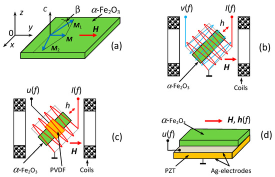
Figure 1.
(a) Schematic view of magnetic structure of hematite; (b) the scheme for excitation and registration of magnetization oscillations in hematite plate; (c) the scheme for observation of ME effect in the hematite-PVDF heterostructure; (d) schematic view of the hematite-PZT heterostructure.
The geometry of magnetoacoustic characteristic measurements in a free hematite plate is shown schematically in Figure 1b. The sample was placed inside two flat electromagnetic coils of rectangular cross section, inserted one into the other. The inner coil had dimensions of 20 mm × 20 mm, and the outer one of 23 mm × 23 mm, each containing 50 turns of 0.3 mm wire. The axes of the coils were directed perpendicular to each other. Orthogonal orientation of the coil axes made it possible to minimize the direct electromagnetic pickup from one coil to another and, at the same time, effectively excite magnetization oscillations in the sample. The entire structure was placed between the poles of an electromagnet in an external permanent magnetic field H with a strength up to 1.5 kOe. The longitudinal axis of the sample was oriented at an experimentally found angle of ~190 to the direction of the permanent field H, at which the magnetization oscillations were most effectively excited. A current with an amplitude up to I = 200 mA and a frequency of f = 0–500 kHz was passed through the internal coil from an Agilent 33210A generator (Agilent Technologies, Santa Clara, CA, USA), which created an excitation magnetic field with an amplitude h up to 2 Oe. Oscillations of the sample magnetization were recorded with an external measuring coil. The dependences of the voltage V induced in the measuring coil on the amplitude h and frequency f of the excitation field h and field H were measured using an SR844 lock-in amplifier (SRS, Sunnyvale, CA, USA). The permanent magnetic field H was measured using a LakeShore 421 Gaussmeter (Lake Shore Cryotronics, Westerville, OH, USA) with an accuracy of 0.1 Oe. The ac excitation field h was measured using the current through the coil calibrated at a frequency of 100 Hz. The measuring setup operated in automatic mode under the control of a specialized program.
To study ME effects, two heterostructures were fabricated. The first heterostructure (Figure 1c) contained a hematite plate and a piezoelectric film of poly(vinylidene fluoride) (PVDF-polymer), mounted in the center of the plate with a cyanoacrylate glue. The piezopolymer was chosen as the PE layer because it has low mechanical rigidity and, at the same time, a high piezoelectric-modulus-to-permittivity ratio. The film had in-plane dimensions of 10 mm × 2 mm, thickness of ap = 50 μm, piezoelectric modulus of d31 ≈ 10 pC/N and relative permittivity of ε ≈ 10.4. Ag-electrodes with a thickness of ~1 μm were preliminarily deposited on the film surface using the thermal method. The ME effect was excited by an alternating magnetic field h(f) produced by the excitation coil. The voltage u(f) generated by the structure was taken across the electrodes of the PVDF-layer. The amplitude of the ME voltage was recorded at different values of f, h, and H.
The second heterostructure (Figure 1d) contained a hematite plate and a plate of piezoelectric lead-zirconate titanate Pb(Zr0.52Ti0.48)O3 ceramic (PZT). The PZT plate had in-plane dimensions of 17 mm × 6 mm, thickness of ap = 250 μm, piezoelectric modulus of d31 = −175 pC/N and relative permittivity of ε ≈ 1750. The Ag-electrodes with a thickness of ~3 μm were preliminarily deposited on the wafer surface using the firing method. The hematite and PZT layers were bonded with a ~4 μm thick cyanoacrylate adhesive, which provided a strain transfer between the layers. The same setup was used to record the ME voltage u(f) generated by the PZT layer at different values of f, h and H.
The magnetization curves of the hematite plate M(H) were measured using a Lakeshore vibrating magnetometer in the field range of H = 0–18 kOe with magnetization along the long axis. The field dependence of hematite magnetostriction λ(H) was measured using a strain gauge glued to the surface of a hematite plate [21] with an accuracy of δλ ≈ 0.2 × 10⁻⁶. All measurements were carried out at room temperature without electromagnetic shielding of the structures.
3. Results
3.1. Magnetization and Magnetostriction of Hematite
Figure 2 shows the magnetization curves for a free α-Fe2O3 plate when magnetized by field H along the long axis. It can be seen from Figure 2a that the magnetization M is equal to zero in the region of fields close to zero H ≈ 0, then increases abruptly to the value M ≈ 2 emu/cm3 and grows linearly with a further increase in the field H up to 18 kOe. Features of magnetization reversal in the region of low fields with a cyclic change in the field are shown in an expanded scale in Figure 2b. It can be seen that the magnetization M begins to grow from zero in the field Hc ≈ 2 Oe and then smoothly increases with increasing H. As the field H falls from maximum to zero and its direction changes, a hysteresis occurs. The magnetization drops abruptly in the field Hc ≈ −2 Oe and the process is repeated. The value of the coercive force was Hc ≈ 2 Oe.
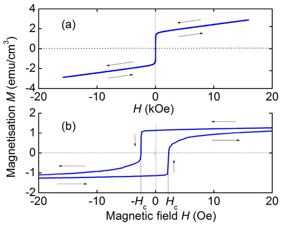
Figure 2.
Magnetization curves for the hematite plate: (a) in the high field region; (b) in the low field region. The arrows show directions of the field change.
Figure 3a shows the dependence of the longitudinal magnetostriction λ(H) of the hematite plate on the field H applied in the plane along the sample length. The magnetostrictive strain λ first grows from zero to λS ≈ 2.5 × 10⁻⁶ with an increase in H up to ~300 Oe, and then increases approximately linearly with an increase in the field. Solid and dashed lines in Figure 3a show the calculated field dependences of the magnetostriction λ(H) and the piezomagnetic coefficient , which is equal to the derivative of the magnetostriction with respect to the field. Saturation of the hematite magnetostriction in the range of fields up to 1.5 kOe was not observed.
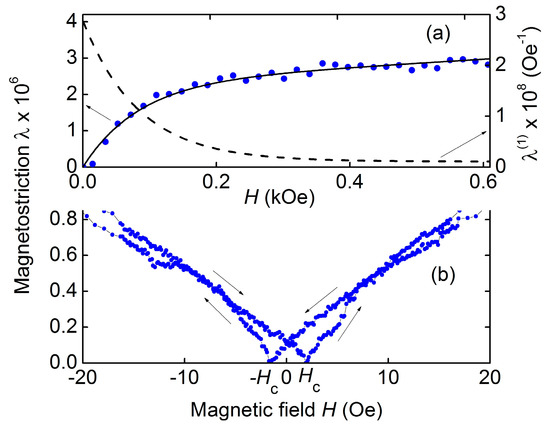
Figure 3.
Dependences of hematite magnetostriction λ vs. magnetic field H: (a) points are the data, solid line is the calculation, dashed line is the piezomagnetic modulus vs. field; (b) magnetostriction λ vs. field H in the low field region. The arrows show directions of the field change.
Figure 3b shows the field dependence of the hematite magnetostriction in the low field region H < 20 Oe. It can be seen that the magnetostriction increases approximately linearly with the field and exhibits a hysteresis as the field direction is changed. The coercive force, as for the magnetization curve, was approximately Hc ≈ 2 Oe.
3.2. Frequency Tuning of Acoustic Resonance of Hematite
At the first stage, the magnetoacoustic characteristics of a free hematite plate were studied. Oscillations of the plate magnetization were excited by an alternating harmonic magnetic field h created by the first coil, and the output signal V was taken from the receiving coil, as shown in Figure 1b.
Figure 4 shows a typical dependence of the voltage amplitude V from the receiving coil on the frequency f of the excitation field with an amplitude h ≈ 0.3 Oe for a hematite plate at H = 50 Oe. Several peaks are visible on the characteristic: near the frequency f1 ≈ 165 kHz with an amplitude of ~4.3 mV and a quality factor Q1 ≈ 110, near the frequency f2 ≈ 314 kHz with an amplitude of ~2.7 mV and a quality factor Q2 ≈ 150, and a peak near the frequency ~394 kHz. The quality factor of the peaks was estimated using the formula Q = f/Δf, where f is the center frequency of the peak, and Δf is the peak width at a level of 0.71 from the maximum. As will be shown later, the peak with frequency f1 corresponds to the excitation of the fundamental mode of planar vibrations along the length of the plate and the peak with frequency f2 corresponds to the excitation of the main contour-shear mode of the plate. Other low-amplitude peaks, corresponding to the excitation of higher modes of planar, bending or shear vibrations of the plate will not be considered further.
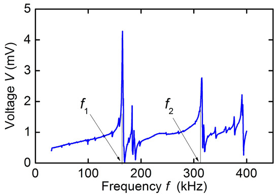
Figure 4.
Frequency response of the hematite plate under excitation and registration of acoustic vibrations by coils at excitation field h = 0.3 Oe and bias field H = 50 Oe.
Figure 5 demonstrates a frequency tuning of the peaks as the field H is increased from zero to 0.6 kOe. The relative frequency tuning of resonances of a hematite plate
where is the limiting frequency in high fields corresponding to the layer saturation, and f(H) is the resonance frequency at field H. For the first mode with frequency f1, the frequency tuning was γ1 ≈ 23.4%, and for the second mode with frequency f2, γ2 ≈ 37.1%. When evaluating the frequency tuning, = 197 kHz was taken for the first mode, and = 425 kHz for the second mode. Quality factors for both resonances increased from Q ≈ 60 in low fields to Q ≈ 4 × 10³ in the saturation field. The dependences obtained are consistent with the data of [13,22]. Solid lines in Figure 5 show calculated dependences of the peak frequencies on the bias field (see below).
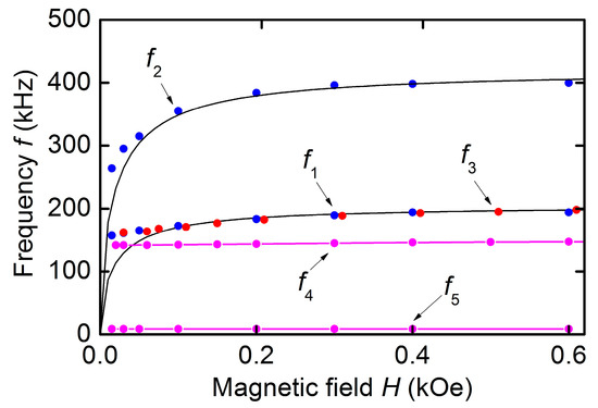
Figure 5.
Magnetic field dependences of resonance frequencies f1 and f2 for the hematite plate (blue dots), resonance frequency f3 for the hematite-PVDF heterostructure (red dots), and resonance frequencies f4 and f5 for the hematite-PZT heterostructure (purple dots and lines). Points are the data and black solid lines are the calculation using Equation (3).
3.3. ME Effect in Hematite-PVDF Heterostructure
At the second stage, the frequency and field characteristics of the ME effect in the hematite-PVDF heterostructure were studied. The structure was excited by an alternating magnetic field h generated by the excitation coil, and the output voltage u was taken across the electrodes of the PVDF layer, as shown in Figure 1c.
Figure 6 shows the dependences of the voltage u on the frequency f of the excitation field with an amplitude h ≈ 0.2 Oe for different values of the bias field H. All the dependences clearly show a resonant peak corresponding to excitation of planar acoustic oscillations of the structure. The peak center frequency f3 is tuned within ~162–200 kHz with increasing H. The peak amplitude u3 first increases with increasing H, reaches a maximum value u3 ≈ 0.058 mV at magnetic fields H = 50–300 Oe, and then decreases gradually as the field increases. The quality factor of the peak in this case increased from Q ≈ 50 to ~150. The dependence of the frequency f3 on the magnetic field H plotted using data of Figure 6 is shown in Figure 5. It can be seen that the relative frequency tuning of the acoustic resonance in the hematite-PVDF structure by magnetic field was ~24%. No peaks were observed on the u(f) characteristic in the high-frequency region of 260–400 kHz.
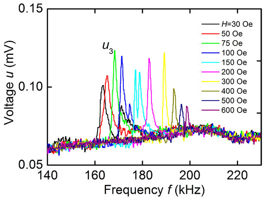
Figure 6.
Dependences of the ME voltage u on the excitation field frequency f for the hematite-PVDF heterostructure at different magnetic fields H.
3.4. ME Effect in Hematite-PZT Heterostructure
At the third stage, the characteristics of ME effect in the hematite-PZT heterostructure were studied. Figure 7 shows the dependence of the voltage u generated by the PZT layer of the structure on the frequency f of the excitation magnetic field for h = 1.3 Oe and bias field H = 10 Oe. The dependence was measured for orientation of the permanent field H and the excitation field h along the longitudinal axis of the structure, as shown in Figure 1d.
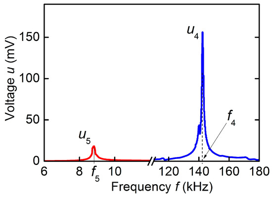
Figure 7.
Dependence of the ME voltage u on the excitation field frequency f for the hematite-PZT heterostructure at excitation field h = 1.3 Oe and bias field H = 10 Oe. The blue and red peaks correspond to acoustic resonance in the plane of the structure and bending resonance of the structure, respectively.
Two resonances are visible on the curve: a resonance near the frequency f4 ≈ 142.5 kHz with an amplitude u4 = 156 mV and a quality factor Q ≈ 180, and a weaker resonance near the frequency f5 ≈ 8.8 kHz with an amplitude u5 ≈ 18 mV and a quality factor Q ≈ 50. The peak with frequency f4 corresponds to the excitation of the lowest mode of planar vibrations along the length of the heterostructure, and the low-frequency peak with frequency f5 corresponds to the excitation of bending vibrations of the heterostructure. With an increase in the field H, an increase in the frequencies of both peaks was observed. The frequency f4 increased from 141.5 kHz at H = 0 to ~147.8 kHz at H = 600 Oe, which corresponds to the frequency tuning by γ ≈ 4.4%. The dependences of the frequencies f4 and f5 on the magnetic field H for the hematite-PZT heterostructure are shown in Figure 5.
Figure 8a shows the dependence of the voltage u4 of the peak with frequency f4 on the bias field H. It can be seen that u4 first decreases monotonically from the maximum value of ~156 mV at H ≈ 0 to ~70 mV at H ≈ 0.3 kOe, and then remains approximately constant as the field increases up to 1.5 kOe. One can see a pronounced dip in the region of fields near zero H ≈ 0. The fine structure of the dependence u4(H) in the low field region is shown in Figure 8b. The peak amplitude hysteretically depends on the field H, reaching a minimum in the fields Hmin ≈ ±2 Oe. In the absence of a field, H = 0, the ME voltage u4 was ~70% of the maximum value at H ≈ 2.5 Oe. For a low-frequency resonance with a frequency f5, the dependences of the voltage u5 on the magnetic field H had the form similar to the dependences shown in Figure 8.
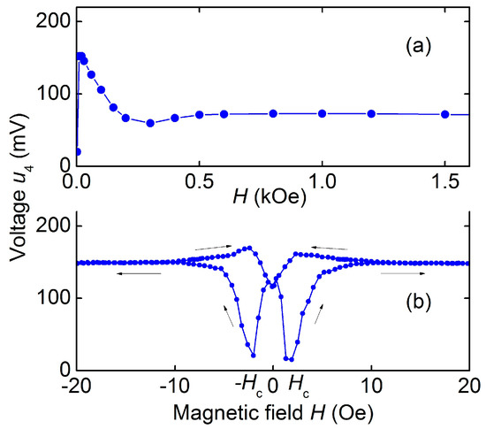
Figure 8.
Dependence of the ME voltage u4 on the magnetic field H for the hematite-PZT heterostructure at excitation field h = 1.3 Oe and frequency 142 kHz: (a) in the wide field region; (b) in the low field region. The arrows show directions of the field change.
3.5. Second Harmonic Generation
With an increase in the excitation field amplitude h, the generation of the second voltage harmonic was observed in the hematite-PZT structure. The structure was excited by a field h with a frequency equal to half the resonance frequency, and the voltage with a doubled frequency, equal to the resonance frequency was recorded. The second harmonic generation was observed only in the region of permanent fields H near zero.
Figure 9 shows the dependence of the second harmonic amplitude on the field H when the structure is excited by a field with a frequency f1/2 = 70.8 kHz and an amplitude h ≈ 1.3 Oe. One can see a voltage peak with an amplitude of ~170 mV and a width at the base δH ≈ 2 Oe. The peak amplitude and peak width increased approximately linearly with increasing excitation field h. Note that the amplitude of the peak is comparable to the amplitude of the voltage generated at linear ME effect (see Figure 7). When generating the second harmonic, there was also a hysteresis on the magnetic field.
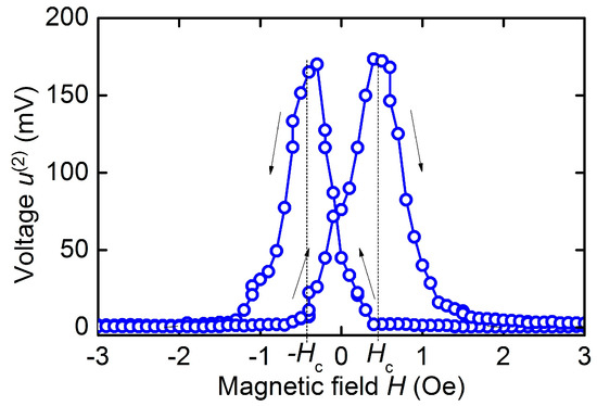
Figure 9.
Dependence of the second voltage harmonic on permanent field H for the hematite-PZT heterostructure at excitation field h = 1.3 Oe and frequency 70.85 kHz. The arrows show directions of the field change.
4. Discussion of Results
First of all, we note the features of magnetization and magnetostriction of a hematite plate, which determine characteristics of ME effects in heterostructures with hematite layers.
As can be seen from Figure 2, the hematite magnetization M rapidly increases from zero to M ≈ 2 emu/cm3 in weak magnetic fields. Using the magneto-optical method, it was shown [23] that in this field region, as H increases, the domain structure of the sample is rearranged, leading to the formation of a single-domain state. With a further increase in H up to 20 kOe, the magnetization grows linearly with the field due to the canting of the sublattices magnetizations in the field direction. In the fields ranging up to several kOe, the resulting magnetization of hematite M is small. Therefore, the demagnetization effects are also small and should not affect the characteristics of ME effects. Consequently, the field characteristics of ME effects in heterostructures with hematite layers will not depend on the layers size, in contrast to heterostructures with FM layers, where demagnetization effects play a significant role [24,25].
The field dependence of the hematite magnetostriction λ(H), as can be seen from Figure 3a, differs qualitatively from the typical field dependence of magnetostriction of FM materials used in ME heterostructures. In low fields, λ of hematite grows approximately linearly with the field (not quadratically, as in ferromagnets), then its growth rate slows down. In high fields, λ again grows linearly with increasing field, but more slowly. =A similar dependence λ(H) for hematite was observed in [26,27], where it was also shown that value of the magnetostriction in high fields depends on the sample shape and orientation of the field H.
The measured field dependence of hematite magnetostriction is described by
where the experimentally found parameters λS = 2.31 × 10⁻⁶, α = 0.012 Oe−1 and τ = 1.1 × 10⁻³ Oe−1 are taken. The calculated curve is shown with a solid line in Figure 3a. The dashed line in Figure 3a shows the field dependence of the piezomagnetic coefficient , found by differentiating the function (2). The maximum coefficient was ~2.8 × 10⁻⁸ Oe−1, i.e., an order of magnitude smaller than for Metglas [10].
A unique property of antiferromagnets with easy-plane anisotropy is a giant frequency tuning of acoustic resonance by magnetic field, which occurs due to the strong coupling of magnetic and acoustic subsystems of the material [17,18]. The magnetoelastic coupling leads to a renormalization of elastic moduli of the material followed by a magnetic field dependence of the acoustic resonance frequencies of the sample—the so-called delta-E effect. The dependence of the resonance frequency f on the field H is given by the following formula [18]:
where is the maximum frequency corresponding to the saturated magnetoelastic coupling, HD = 22 kOe is the Dzyaloshinski field, HE = 9.2 × 10³ kOe is the effective exchange field [15], and Hms is the magnetostriction field. Here, is for the contour-shear mode and is for the longitudinal mode, where β is the angle between magnetic field H and the binary axis U2.
The dependences of the resonance frequencies f1 and f2 on the field H calculated using Equation (3) are shown with solid lines in Figure 5. The parameters of the hematite plate found from experiment 2HEHms ≈ 2.2 kOe2, = 197 kHz, = 425 kHz, and angle β = 190 were used in calculations. The limiting frequencies can be estimated by the formulas: for planar vibrations along the plate length L and for contour-shear vibrations along the plate width W. Calculation for a hematite plate of length L = 17 mm, width W = 5 mm, Young’s modulus Y = 23 × 1010 N/m2, and shear modulus C66 = 9.3 × 10¹⁰ N/m2 [13], gives the frequencies 193 kHz and 419 kHz, respectively. Thus, the theory explains the field dependences of the resonance frequencies of hematite plate well.
For the hematite-PVDF heterostructure, the field dependence of the resonance frequency f3(H), as can be seen from Figure 3, completely coincided with the dependence f1(H) for a free hematite plate. This indicates that a thin PVDF film deposited on the hematite surface did not affect its magnetoacoustic characteristics. The frequency tuning of the resonant ME effect under magnetic field in the structure under study was ~24%, i.e., an order of magnitude greater than the frequency tuning due to the delta-E effect in structures with various FM materials: 1% in the structure with permendure (FeCoV) [5], 1.4% in the structure with amorphous FeGaB alloy [28], and 3.9% in the structure with Terfenol-D [29]. The maximum value of ME voltage coefficient for the hematite-PVDF heterostructure, as follows from data in Figure 6 was 58 mV/(Oe∙cm) at a bias field of H ≈ 75–100 Oe. It is seen from Figure 6 that the resonant peak splits in magnetic fields of H ~ 100–150 Oe. This may be due to the intersection at a given field of the dispersion curves of vibration modes with close frequencies, which was recently observed in hematite disk resonators [22]. A lack of ME effect in the hematite-PVDF heterostructure at the frequency of contour-shear vibrations f2 is explained by the non-responsivity of the PVDF film to shear deformations.
It is seen from Figure 5, that the resonance frequency f4 of the hematite-PZT heterostructure increased by 4.5% with increasing H, i.e., the frequency tuning decreased by a factor of ~6 compared to the frequency tuning for a free hematite plate. The mechanism of magnetoelastic excitation in the geometry of Figure 1d is modulation of the non-saturated magnetostriction by the longitudinal alternating magnetic field. Longitudinal susceptibility in the fields up to 1.5 kOe is mainly determined by the residual growth stresses and weakly dependents on magnetizing field. As a result, the sensitivity of the magnetoelastic coupling to the magnetic field variations also deceases.
The limiting frequencies of the lowest modes of planar f4 and bending f5 resonances for the hematite-PZT structure were estimated using the formulas for the natural vibration frequencies of a free rod [30]. Taking into account dimensions of the structure, effective values of Young’s modulus Yef = 16.1 × 10¹⁰ N/m2 and density 6.2 × 10³ kg/m3, the frequencies f4cal ≈ 149.2 kHz and f5cal ≈ 8.02 kHz were obtained, which are in good agreement with the measured ones. The maximum value of the ME voltage coefficient for the hematite-PZT heterostructure, as follows from the data in Figure 8, was 4.8 V/(Oe∙cm) at a bias field of H ≈ 2.5 Oe.
It can be seen from Figure 8a that the field dependence of ME voltage u4(H) for the hematite-PZT heterostructure qualitatively differs from similar dependence for the structures with FM layers. This is due to the unusual field dependence of the magnetostriction λ(H) and piezomagnetic coefficient of hematite, which are shown in Figure 3a. It is known that in composite heterostructures with a stress-mediated ME effect, the dependence u(H) qualitatively repeats field dependence of the piezomagnetic modulus of magnetic layer [4]. Comparison of the curves in Figure 3a and u4(H) in Figure 8a confirms this connection. The quantitative difference between the experiment and theory can be due to a change in the shape of the dependence λ(H) for a hematite plate loaded with a PZT layer.
Finally, we note the high efficiency of the second voltage harmonic generation in the hematite-PZT heterostructure. Using the data in Figure 9, we obtain a nonlinear ME coefficient 4 V/(cm∙Oe2), which is comparable to the coefficient for the Metglas-PZT structure ~4.5 V/(cm∙Oe2) and exceeds by an order of magnitude the coefficients for structures with Ni or FeCo layers [31]. The high nonlinearity of ME effect is due to peculiarities of the hematite magnetostriction: the linear field dependence of the magnetostriction in low fields H ≈ 0 and symmetry of the magnetostriction with respect to the field direction λ(H) = λ(−H) (see Figure 3b). Therefore, the amplitude of the second harmonic at H ≈ 0 is proportional to the magnetostriction u(2)~λ, and not to its second derivative , as for the structures with ferromagnetic layers. The amplitude u(2) should be maximum at H = 0 and drop to zero with increasing magnetic field up to H ≈ h, which was observed experimentally. A decrease in the hysteresis of the nonlinear ME effect during second harmonic generation (see Figure 9) down to Hc ≈ 0.5 Oe compared to the hysteresis of linear ME effect (Figure 8b) may be due to suppression of ME effect hysteresis with an increase in the amplitude of the excitation magnetic field [32].
The above features of ME effects in heterostructures with hematite layers make it possible to expand the functionality of magnetic field sensors. In particular, magnetic tuning of the resonant frequency of the hematite-PVDF and hematite-PZT heterostructures can be used to fine-tune the sensors to the frequency of the measured alternating magnetic field. The dependence of the acoustic resonance frequency of heterostructures on the field makes it possible to elaborate self-oscillating permanent magnetic field sensors with a frequency output. The unambiguous dependence of ME voltage at the resonance frequency on the field in the hematite-PZT heterostructure can be used in sensors of permanent magnetic fields. The strong nonlinearity of the heterostructures allows for the realization of frequency doublers operating without a bias field.
5. Conclusions
Thus, we observed and investigated the direct resonant ME effect in heterostructures with a magnetostrictive layer of antiferromagnetic hematite α-Fe2O3 single crystal and piezoelectric layers of PVDF polymer or PZT piezoceramics. The dependences of the magnetization M and magnetostriction λ of a hematite plate on the permanent magnetic field are measured. It is shown that the strong coupling of magnetic and acoustic subsystems in the hematite crystal leads to a change in its rigidity (delta-E effect) and allows one magnetic tuning of the acoustic resonance frequency of crystals up to ~37%. In the hematite-PVDF heterostructure, the frequency tuning of planar acoustic resonance by magnetic field reached 24%, and the value of ME coefficient was 58 mV/(Oe∙cm). In the hematite-PZT heterostructure, the resonance frequency tuning by magnetic field reached ~4.4%. The ME coefficient in weak magnetic fields was ~4.8 V/(Oe∙cm) and monotonically decreased with increasing field. Efficient generation of the second voltage harmonic in the hematite-piezoceramic heterostructure in the absence of a bias field was found. The results show that by choosing the material and the size of the PE layer in bilayers with hematite, it is possible to realize both a wideband magnetic tuning of the resonance frequency and a high efficiency of ME conversion. The ME effects in heterostructures with layers of antiferromagnetic hematite single crystals open up new possibilities for creating magnetic field sensors.
Author Contributions
D.A.B.: measurements of magnetostriction and magnetoelectric characteristics of the structures. D.V.C.: preparation of the samples. N.A.E.: measurements of magnetoacoustic characteristics of the hematite crystal. L.Y.F.: measurements of magnetization of the hematite crystal. V.L.P.: calculation of tuning characteristics of the hematite crystal and the structures, proofreading the manuscript. Y.K.F.: overall management, writing of the article. All authors have read and agreed to the published version of the manuscript.
Funding
This research was funded by the Russian Science Foundation, project no. 22-29-01093.
Institutional Review Board Statement
Not applicable.
Informed Consent Statement
Not applicable.
Data Availability Statement
The data that support the findings of this study are available from the corresponding author upon reasonable request.
Acknowledgments
The authors are thankful to V.A. Murashov for providing the hematite sample. Some of the measurements were made on the equipment of the Joint Center for Collective Use of RTU MIREA.
Conflicts of Interest
The authors declare no conflict of interest. The funding sponsors had no role in the design of the study; in the collection, analyses, or interpretation of data; in the writing of the manuscript; or in the decision to publish the results.
References
- Gao, J.; Jiang, Z.; Zhang, S.; Mao, Z.; Shen, Y.; Chu, Z. Review of magnetoelectric sensors. Actuators 2021, 10, 109. [Google Scholar] [CrossRef]
- Kumar, A.; Kaur, D. Magnetoelectric heterostructures for next-generation MEMS magnetic field sensing applications. J. Alloys Compd. 2022, 897, 163091. [Google Scholar] [CrossRef]
- Van Suchtelen, J. Product properties: A new application of composite materials. Philips Res. Rep. 1972, 27, 28–37. [Google Scholar]
- Nan, C.-W.; Bichurin, M.I.; Dong, S.; Viehland, D.; Srinivasan, G. Multiferroic magnetoelectric composites: Historical perspective, status, and future directions. J. Appl. Phys. 2008, 103, 31101. [Google Scholar] [CrossRef]
- Filippov, D.A.; Laletin, V.M.; Poddubnaya, N.N.; Galichyan, A.; Zhang, J.; Srinivasan, G. Magnetoelectric and magnetostriction characteristics of symmetric three layered structures of nickel-lead zirconate titanate–nickel and permendure–lead zirconate titanate–permendure. IOP Conf. Ser. Mater. Sci. Eng. 2020, 939, 012023. [Google Scholar] [CrossRef]
- Liang, X.; Dong, C.; Chen, H.; Wang, J.; Wei, Y.; Zaeimbashi, M.; He, Y.; Matyushov, A.; Sun, C.; Sun, N. A Review of thin-film magnetoelastic materials for magnetoelectric applications. Sensors 2020, 20, 1532. [Google Scholar] [CrossRef]
- Dong, S.; Zhai, J.; Bai, F.; Li, J.; Viehland, D.; Lograsso, T.A. Magnetostrictive and magnetoelectric behavior of Fe–20at.% Ga/Pb(ZrTi)O3 laminates. J. Appl. Phys. 2015, 97, 103902. [Google Scholar] [CrossRef]
- Srinivasan, G.; De Vreugd, C.P.; Laletin, V.M.; Paddubnaya, N.; Bichurin, M.I.; Petrov, V.M.; Filippov, D.A. Resonant magnetoelectric coupling in trilayers of ferromagnetic alloy and piezoelectric lead zirconate titanate: The influence of bias magnetic field. Phys. Rev. B 2005, 71, 184423. [Google Scholar] [CrossRef]
- Bichurin, M.I.; Filippov, D.A.; Petrov, V.M.; Laletsin, V.M.; Paddubnaya, N.; Srinivasan, G. Resonance magnetoelectric effects in layered magnetostrictive-piezoelectric composites. Phys. Rev. B 2003, 68, 132408. [Google Scholar] [CrossRef]
- Fetisov, L.Y.; Burdin, D.A.; Ekonomov, N.A.; Chashin, D.V.; Zhang, J.; Srinivasan, G.; Fetisov, Y.K. Nonlinear magnetoelectric effects at high magnetic field amplitudes in composite multiferroics. J. Phys. D Appl. Phys. 2018, 51, 15400321. [Google Scholar] [CrossRef]
- Fetisov, Y.K.; Burdin, D.A.; Ekonomov, N.A.; Fetisov, L.Y.; Berzin, A.A.; Hyes, P.; Quandt, E. Bistability in a multiferroic composite resonator. Appl. Phys. Lett. 2018, 113, 022903. [Google Scholar] [CrossRef]
- Morrish, A.H. Chapter 2—Canted antiferromagnetism: Hematite. In Crystal Growth and Characterization of Hematite; World Scientific Publishing Co.: Singapore, 1995. [Google Scholar] [CrossRef]
- Andruschak, E.A.; Evtikhiev, N.N.; Pogozhev, S.A.; Preobrazhensky, V.L.; Ekonomov, N.A. Acoustic vibrations in antiferromagnetic resonators. Sov. Phys. Acoust. 1981, 27, 170–178. [Google Scholar]
- Dubenko, I.S.; Kiselev, A.O.; Murashov, V.A.; Preobrazhensky, V.L. Influence of impurities and technology on thermostability of magneto-acoustic parameters of hematite. Non-Org. Mater. 1991, 27, 1850–1854. [Google Scholar]
- Strugatsky, M.B.; Skibinsky, K.M. Acoustic resonances in antiferromagnet FeBO3. J. Magn. Magn. Mater. 2007, 309, 64–70. [Google Scholar] [CrossRef]
- Evdokimov, A.A.; Murashov, V.A.; Preobrazhensky, V.L. Growth and magnetoacoustic properties of hematite crystals. In Crystal Growth 1983: Proceedings of the Seventh International Conference on Crystal Growth, Stuttgart, Germany, 12–16 September 1983; Tolksdorf, W., Ed.; North-Holland Physics Publisher: North-Holland, The Netherlands, 1983; Volume 5, p. 70. [Google Scholar]
- Seavey, M.H. Acoustic resonance in the easy-plane weak ferromagnets α-Fe2O3 and FeBO3. Solid State Commun. 1972, 10, 219–223. [Google Scholar] [CrossRef]
- Ozhogin, V.I.; Preobrazhenskii, V.L. Anharmonicity of mixed modes and giant acoustic nonlinearity of antiferromagnetics. Sov. Phys. Uspekhi 1988, 31, 713–729. [Google Scholar] [CrossRef]
- Popov, M.; Liu, Y.V.; Safonov, L.; Zavislyak, I.V.; Moiseienko, V.; Zhou, P.; Fu, J.; Zhang, W.; Zhang, J.; Qi, Y.; et al. Strong converse magnetoelectric effect in a composite of weakly ferromagnetic iron borate and ferroelectric lead zirconate titanate. Phys. Rev. Appl. 2020, 14, 034039. [Google Scholar] [CrossRef]
- Dzyaloshinsky, I. A Thermodynamic theory of “weak” ferromagnetism of antiferromagnetics. J. Phys. Chem. Solids 1958, 4, 241–255. [Google Scholar] [CrossRef]
- Chashin, D.V.; Burdin, D.A.; Fetisov, L.Y.; Ekonomov, N.A.; Fetisov, Y.K. Precise measurements of magnetostriction of ferromagnetic plates. J. Sib. Fed. Univ. Math. Phys. 2018, 11, 30–34. [Google Scholar] [CrossRef]
- Moshkin, V.; Preobrazhensky, V.; Pernod, P. Wide-range frequency control in magnetoacoustic resonator. IEEE Trans.Ultrason. Ferroelectr. Freq. Control 2020, 67, 1957–1959. [Google Scholar] [CrossRef]
- Preobrazhenskii, V.L.; Shishkov, A.A.; Ekonomov, N.A. Magnetooptic registration of domain structure of hematite. Solid State Phys. 1987, 29, 2034–2035. [Google Scholar]
- Lasheras, A.; Gutiérrez, J.; Barandiarán, J.M. Quantification of size effects in the magnetoelectric response of metallic glass/PVDF laminates. Appl. Phys. Lett. 2016, 108, 222903. [Google Scholar] [CrossRef]
- Fedulov, F.A.; Saveliev, D.V.; Chashin, D.V.; Shishkin, V.I.; Fetisov, Y.K. Magnetoelectric effects in stripe- and periodic heterostructures based on nickel–lead zirconate titanate bilayers. Russ. Technol. J. 2022, 10, 64–73. [Google Scholar] [CrossRef]
- Urquhar, H.M.A.; Goldman, J.E. Magnetostrictive effects in an antiferromagnetic hematite crystal. Phys. Rev. 1956, 101, 1443–1450. [Google Scholar] [CrossRef]
- Voskanyan, R.A.; Levitin, R.Z.; Shchurov, V.A. Magnetostriction of a hematite monocrystal in fields up to 150 kOe. Sov. Phys. JETP 1968, 27, 423–426. [Google Scholar]
- Li, M.; Matyushov, A.; Dong, C.; Chen, H.; Lin, H.; Nan, T.; Qian, Z.; Rinaldi, M.; Lin, Y.; Sun, N.X. Ultra-sensitive NEMS magnetoelectric sensor for picotesla DC magnetic field detection. Appl. Phys. Lett. 2017, 110, 145310. [Google Scholar] [CrossRef]
- Lei, C.; Ping, L.; Yu-Mei, W.; Yong, Z. Tunable characteristics of bending resonance frequency in magnetoelectric laminated composites. Chin. Phys. B 2013, 22, 077505. [Google Scholar] [CrossRef]
- Timoshenko, S. Vibration Problems in Engineering; D. Van Nostrand Company Inc.: Toronto, ON, Canada, 1955; pp. 310–312. [Google Scholar]
- Burdin, D.A.; Chashin, D.V.; Ekonomov, N.A.; Fetisov, L.Y.; Fetisov, Y.K.; Srinivasan, G.; Sreenivasulu, G. Nonlinear magnetoelectric effects in planar ferromagnetic-piezoelectric structures. J. Magn. Magn. Mater. 2014, 358–359, 98–104. [Google Scholar] [CrossRef]
- Burdin, D.A.; Chashin, D.V.; Ekonomov, N.A.; Fetisov, L.Y.; Fetisov, Y.K. Suppression of nonlinear magnetoelectric effect hysteresis in a layered ferromagnetic-piezoelectric structure. J. Magn. Magn. Mater. 2018, 449, 152–156. [Google Scholar] [CrossRef]
Disclaimer/Publisher’s Note: The statements, opinions and data contained in all publications are solely those of the individual author(s) and contributor(s) and not of MDPI and/or the editor(s). MDPI and/or the editor(s) disclaim responsibility for any injury to people or property resulting from any ideas, methods, instructions or products referred to in the content. |
© 2023 by the authors. Licensee MDPI, Basel, Switzerland. This article is an open access article distributed under the terms and conditions of the Creative Commons Attribution (CC BY) license (https://creativecommons.org/licenses/by/4.0/).