1. Introduction
Path planning is an essential component of robot motion planning and is a research hotspot in the field of robotics and other related intelligent fields [
1]. Among them, the manipulator, as an important industrial robot, has autonomy and intelligence levels that are crucial for improving production efficiency and quality. Path planning can help the manipulator automatically plan the optimal path, reduce dependence on staff, and improve the autonomy of the manipulator. Path planning can be flexibly adjusted and optimized according to different task characteristics, thereby improving the motion accuracy and speed of the manipulator, which directly affects production efficiency and quality. Compared with a single manipulator, the form of a dual manipulator collaborative operation can meet the needs of complex, intelligent, and compliant modern industrial systems, and dual manipulators have more advantages in efficiency and performance [
2,
3] and are gradually gaining attention in the industry. Path planning for dual manipulators is an important work of collaborative operations [
4]. To enhance the adaptability and flexibility of dual-manipulator systems, it is necessary to flexibly adjust and optimize paths based on various production environments and task requirements. The equipment transformation and upgrading of production lines are of great significance, but there are high requirements for efficiency, real-time performance, and safety in collaborative operations [
5]. To address these challenges, researchers are continuously developing and improving various path planning methods for dual manipulators to enhance their efficiency and precision and meet different demands in industrial production environments. Therefore, different path planning algorithms need to be designed or selected for various fields to achieve the goal of fast matching and application.
2. Related Work
The classic 3D path planning algorithms for robots can be roughly divided into three categories. The first type of path planning algorithm is based on searches, such as Dijkstra and A* algorithms [
6,
7]. This algorithm is based on a graph structure in which each node represents the robot’s location, and each edge represents its movement path. By searching through the graph structure and calculating a heuristic function for each node to evaluate the distance to the endpoint, the optimal path is found. Qing et al. [
8] proposed an improved Dijkstra algorithm that saves all equidistant shortest paths during the path search process, although it can solve several shortest path planning problems; in some cases, it may be difficult to obtain the complete graph structure, and there are issues such as large search space, high computational complexity, and poor real-time performance.
The second type of path planning algorithm is based on rules, such as the artificial potential field method [
9,
10]. The main idea is to design an artificial potential field to simulate the perception and decision-making process of the robot during movement and achieve path planning. The artificial potential field method has the advantages of simple algorithm implementation, easy understanding and use, rapid calculation of robot movement paths, and high real-time performance. Therefore, Xia et al. [
11] proposed an improved velocity potential field (IVPF) algorithm based on the artificial potential field method to address the inherent drawbacks of traditional algorithms. However, utilizing tangential velocity to avoid local minimum problems leads to poor path quality. The artificial potential field method only considers the relationship between the robot and obstacles, ignoring the constraints among robots themselves, which may lead to locally optimal solutions in some cases.
To address this issue, the third type of path planning algorithm based on sampling is widely applied in various fields, such as the rapidly exploring random tree (RRT) [
12] and probabilistic roadmap (PRM) [
13]. The main idea is to search for the optimal feasible path through random sampling in the environment. Sampling-based algorithms are not limited by the type of environment and can be applied to path planning problems in various complex environments, with high robustness and reliability. Li et al. [
14] improved the PRM algorithm by using a pseudorandom sampling strategy with the spatial principal axis as a reference axis and optimized the path using Bezier curves. However, the roadmap construction rate is unstable in three-dimensional environments. Liu et al. [
15] proposed a grid-local PRM method, which has high efficiency and real-time performance. However, this type of algorithm has weak scalability and a low roadmap reuse rate. To address this issue, the RRT algorithm and its variations have been proposed. The RRT algorithm has wide applicability, high efficiency, strong scalability, good determinism, and real-time computation, which effectively solves the path planning problem with high-dimensional space constraints. As a result, the RRT algorithm has become one of the most commonly used and effective algorithms in path planning.
On this basis, Kuffner et al. [
16] proposed an RRT-connect double tree algorithm by randomly expanding paths at the same time at the start and goal nodes. It is superior to the RRT algorithm in terms of search performance. However, it is difficult to find the optimal path due to randomness. To solve this problem, scholars made some improvements to the RRT-connect algorithm. For example, based on the triangle inequality, Kang et al. [
17] proposed an RRT-connect algorithm based on the triangle inequality principle by re-wiring path nodes, which has outstanding performance in terms of path length. However, there may be problems, such as non-differentiable linear sections with sharp corners and constraints with the kinematics of the manipulator. Based on the idea of dynamic step size [
18], Li et al. [
19] proposed a variable step size RRT (VT-RRT) by transforming the search space of random nodes in the RRT algorithm and adaptively adjusting the search step size according to the goal and the position of obstacles in the current point. This algorithm effectively reduces path planning time and optimizes sampling direction. However, it generates too many path nodes, resulting in longer paths. To improve the adverse effects of variable step size, Zhang et al. [
20] proposed a path planning method for a manipulator based on the artificial potential field and bidirectional rapidly exploring random tree (BiRRT-APF) algorithm, aiming to solve the problem of low search efficiency and high randomness. However, its goal orientation is poor. Shao et al. [
21] proposed a motion planning method based on the goal bias RRT algorithm (G-RRT), which reduces invalid searches by guiding the direction of random sampling. However, the one-way search is less efficient, and the resulting path is not optimal. Liu et al. [
22] proposed a goal bias bidirectional rapidly exploring random tree (GBI-RRT) algorithm, which improves the success rate of node expansion. However, in complex and high-dimensional environments, this algorithm generates redundant nodes, resulting in overly complex paths. The types of path planning algorithms are shown in
Table 1 below, as well as the advantages and disadvantages of each algorithm. Due to the existence of overlapping workspaces, the path planning of dual manipulators should deal with the interference of static and dynamic obstacles at the same time. In response to the above content, a sampling-based RRT path planning algorithm is adopted to improve and optimize the shortcomings of the algorithm and is deployed on a dual manipulator.
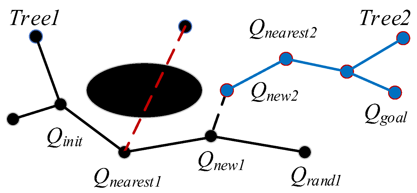
Regarding the aforementioned issues, this paper proposes a bidirectional potential field probabilistic step-size RRT algorithm for the path planning of dual manipulators by angle selection. The main contributions of this paper are as follows:
- (1)
Based on the RRT-connect algorithm and the characteristics of bidirectional searches, the high goal probability bias strategy is introduced to enable the random points to be sampled along the goal direction.
- (2)
Angle selection is used to limit the direction of dual-tree searches and avoid redundant sampling to the surrounding area.
- (3)
Based on the idea of dynamic step size, random values are innovatively used as step size parameters, and the search step size is adaptively adjusted by the dynamic changes of randomness to cope with the environment. The artificial potential field method is introduced to deal with multi-obstacle environments.
- (4)
A greedy algorithm is used for path optimization, removing redundant nodes on the path and finding the shortest path.
The remainder of this article is organized as follows.
Section 3 introduces the posture description and collision detection of the dual manipulator.
Section 4 presents the improved strategies and algorithm flow of the proposed algorithm. In
Section 5, comparative experiments are conducted with RRT-Goalbias, VT-RRT, and goal-biased bidirectional RRT as the control groups, and an ablation experiment is also carried out on the proposed algorithm to validate its performance.
Section 6 provides a path planning case study, deploying the proposed algorithm for obstacle avoidance path planning on a dual-arm robot for simulation verification.
Section 7 outlines limitations and future scope, and
Section 8 presents conclusions.
5. Planning Simulation
5.1. Performance of the BPFPS-RRT Algorithm
The simulation is performed using MATLAB 2020b. The hardware is an Intel (R) Core (TM) i7-12700H CPU. The reference frequency is 2.70 GHz and the memory is 16 G. The initial conditions of the simulation are as follows: the starting point coordinates are [10, 10, 10], the endpoint coordinates are [150, 150, 150], and the initial step size is = 10 mm, = 1.5, and = 1. The five balls of different specifications are simulated as obstacles in a three-dimensional space, and the G-RRT, VT-RRT, and GBI-RRT are selected as the control groups.
Figure 7 shows the search process of the control groups and the proposed BPFPS-RRT.
Figure 7a–d shows the search path process of the G-RRT, VT-RRT, GBI-RRT, and BPFPS-RRT algorithms, respectively. The green and blue dots represent the starting point and the goal point, respectively. The control groups are compared to the BPFPS-RRT. As shown in
Figure 7a, the G-RRT produces redundant sampling in the surrounding environment. As shown in
Figure 7b, the two trees use variable step size sampling, but their tendency toward the goal is poor. As shown in
Figure 7c, the two nodes expand toward each other; however, a large number of tree nodes are generated during the sampling process, and the fixed step size produces a complex path. As shown in
Figure 7d, the proposed algorithm has fewer path nodes, and the search step size can be adaptively adjusted based on the surrounding environment. This method avoids the failure of local planning and improves the efficiency of the path search.
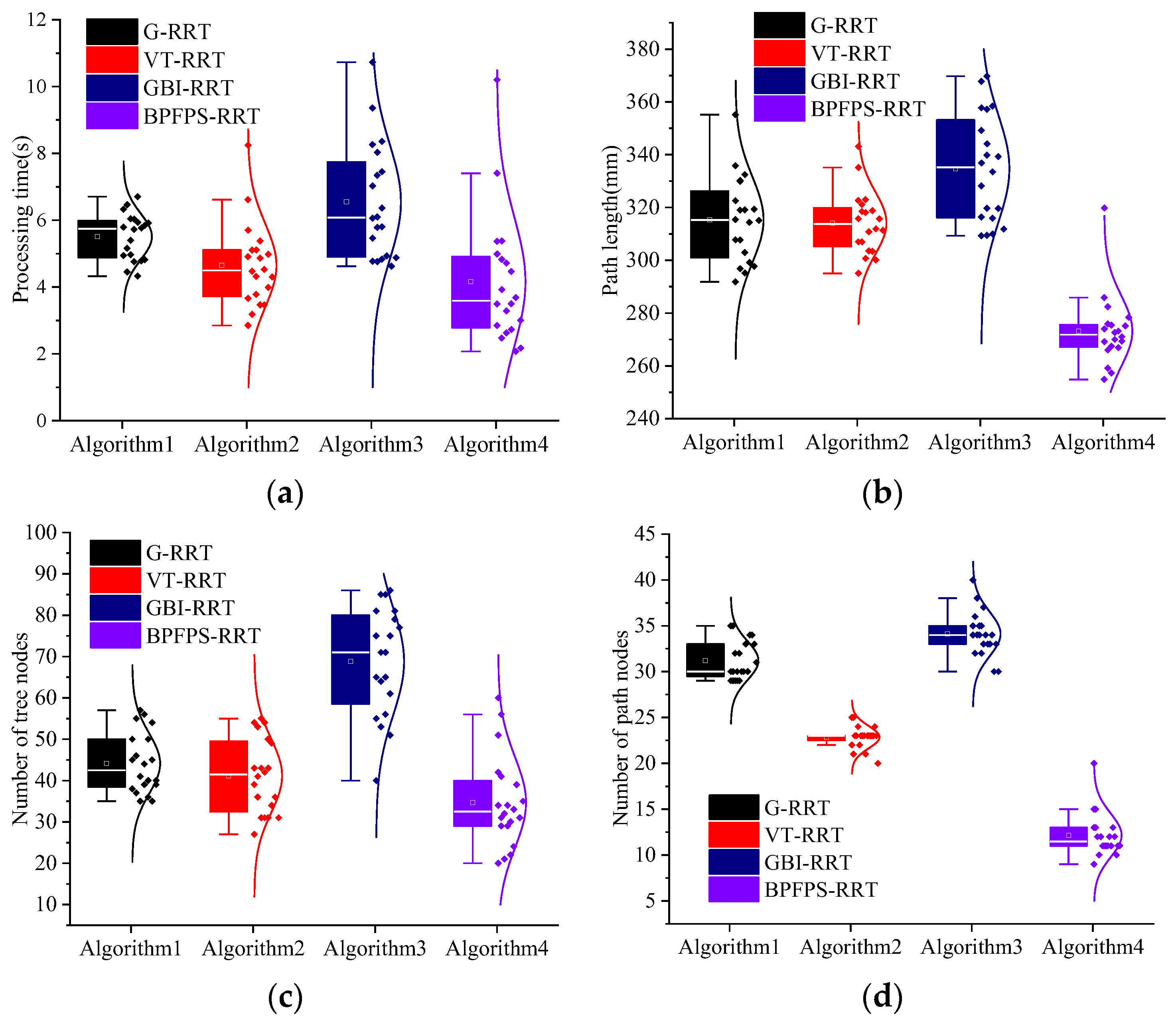
The experiment is repeated 20 times to explore the algorithm search time and planning path performance.
Figure 8a–d shows the search time, path length, tree nodes, and number of path nodes of the four algorithms, respectively. The data differences of each algorithm are visually reflected by the box plot and normal curve.
Table 3 presents the average experimental data of the four algorithms.
Compared to the G-RRT algorithm, the search time is reduced by 24.50% and the number of path nodes is reduced by 58.06%. Because the G-RRT searches in one direction, it is easy to increase the number of path nodes in complex environments. Among them, compared to the G-RRT algorithm, the path length of the BPFPS-RRT algorithm is shortened by 13.38%, and the number of tree nodes is reduced by 20.45%. These results suggest that BPFPS-RRT generates fewer nodes, makes better use of path points, and exhibits better overall performance compared to G-RRT.
The search time of the BPFPS-RRT is 10.76% shorter than the VT-RRT, and the number of tree nodes and path length of the BPFPS-RRT are reduced by 14.63% and 13.03%, respectively. The variable step size of the VT-RRT performs better than the G-RRT and GBI-RRT in complex environments but lacks potential field guidance, and its overall performance is inferior to the BPFPS-RRT. The number of path nodes was reduced by 43.48% compared with the VT-RRT. Based on data comparison, it is found that there are too many redundant nodes present in the vicinity and the path utilization rate is also low.
Compared to the GBI-RRT algorithm, the search time of the BPFPS-RRT is reduced by 36.39%, the path length is shortened by 18.38%, the number of tree nodes is reduced by 48.53%, and the number of path nodes is reduced by 61.76%. Since the fixed step size of the GBI-RRT can easily fall into a dead corner in a complex environment, it jumps out of the local planning by increasing the number of tree nodes. These findings indicate that in complex environments, the BPFPS-RRT exhibits a significant reduction in extension nodes. There is a stronger tendency toward the search goal in its sampling process, the path length is shorter, and it takes less time.
5.2. Ablation Experiment
To further visualize the improvement effects of each optimization strategy, an ablation experiment is conducted. The four main contribution strategies in
Section 2 are, respectively, designated algorithm A, algorithm B, algorithm C, and algorithm D. The basic algorithm is RRT-connect, and the algorithm (A + B + C + D) is called the BPFPS-RRT algorithm. The simulation uses the same specific parameters as above and simulates obstacles in a three-dimensional space using four different sizes of spheres. The coordinates of their centers are (100, 100, 100), (50, 60, 60), (100, 60, 60), and (50, 110, 80), with radii of (30, 20, 20, 20), respectively. The experiment is repeated twenty times, simulation data for five algorithms as shown in
Figure 9, and average experimental data for the five algorithms, as shown in
Table 4, are obtained.
Through box plots and normal distribution curves, it is intuitively reflected that the performance is improved with the addition of each optimization strategy. Combining
Figure 9 and
Table 4 for analysis, algorithm A introduces a high goal probability bias strategy based on RRT-connect, so it improves by 7.28%, 3.35%, 3.41%, and 5.26% in terms of search time, path length, tree nodes, and path nodes compared to RRT-connect, respectively. By increasing the randomness in the search toward the goal direction, although the improvement effect is relatively small, it can provide assistance for subsequent improvements. Algorithm (A + B) adds a strategy that restricts the dual-tree search direction using angle selection, compared to algorithm A. In terms of performance, algorithm (A + B) improves by 23.40%, 8.20%, 24.71%, and 8.33% compared to algorithm A, respectively. It can be observed that there is a significant improvement in search time and tree nodes because the efficiency of searching toward the goal point is further improved by restricting the search direction, and redundant sampling of the surrounding environment is avoided as much as possible. Algorithm (A + B + C) adds a potential field probability step size compared to algorithm (A + B). In terms of performance, algorithm (A + B + C) improves by 37.76%, 14.48%, 40.63%, and 48.48% compared to algorithm (A + B), respectively. The random value is used as the step parameter, which changes with the variation of high goal probability bias, and through the guidance of the artificial potential field method, it can adaptively adjust the search step length. From the analysis of the number of nodes in the algorithm, the improvement is significant, with a reduction of approximately 20 nodes. The reduction in tree and path nodes indicates an improvement in the sampling efficiency of the goal. The search time has been improved by 2 s, and the path length has been significantly improved compared to the previous groups, with a length reduction of nearly 50 mm; this has resulted in a qualitative improvement in overall performance. The BPFPS-RRT adds a path optimization strategy compared to algorithm (A + B + C). In terms of performance, the BPFPS-RRT improves by 2.74%, 6.98%, 7.89%, and 41.18% compared to algorithm (A + B + C), respectively. The greedy algorithm optimizes the path mainly by trimming the path nodes and removing redundant nodes so that the path quality is improved. There is a significant improvement in the performance of the path nodes, with the optimized path length reduced by approximately 20 mm. The search time is improved by about 0.09 s, which can be ignored as it is an optimization of the path and has no effect on the search efficiency and falls within the normal fluctuation range.
Through the ablation experiment, the simulation experiments are conducted for each improvement strategy point, and it can be seen that among the five sets of simulation data comparisons, the performance improvement of the algorithm after adding the potential field probability step size is the largest, which is also the most important improvement point in this paper.
6. Path Planning Case
The three-dimensional obstacle environment and the dual manipulator model are set up to verify the effectiveness of the obstacle avoidance path planning of the dual manipulator. The collision detection model of the boundary ball is adopted. Four spherical static obstacles with a radius of 0.1 cm were established, and their center locations, along with the motion parameters of the manipulator, are presented in
Table 5. In this section, the units of the parameters
,
,
, and
are all in centimeters.
The obstacles are placed on the path of the dual manipulator moving toward the goal point.
Figure 10 shows the dual manipulator pathless planning scenario, where the red and blue colors represent the obstacle avoidance trajectory of the main manipulator and the obstacle avoid-ance trajectory of the slave manipulator, respec-tively. As depicted in
Figure 10a,c, in the ab-sence of an obstacle avoidance path, the slave manipulator collides with the main manipulator during the dual manipulator’s motion. As shown in
Figure 10b, the dual manipulator col-lides with static obstacles, and the final motion trajectory without path planning is shown in
Figure 10d. Throughout the entire motion pro-cess, the slave manipulator failed to avoid ob-stacles and the moving main manipulator. While the environment around the dual manip-ulator is unchanged, the BPFPS-RRT path plan-ning algorithm is deployed in the simulation.
Figure 11 shows the motion process of the dual manipulator,
Figure 11a shows the initial movement of the dual manipulator, and both are without contact with obstacles.
Figure 11c,d show the obstacle avoidance process of the dual manipulator. It is observed that the dual ma-nipulator avoids obstacles, and the slave ma-nipulator avoids not only obstacles but also the moving main manipulator without collision.
Figure 11d shows the final state of movement of the dual manipulator.
Figure 12 depicts the change in joint angles in the dual manipulator, where the sampling interval is represented by the abscissa N. As shown in
Figure 12a, the obstacle avoidance process during the main manipulator’s motion from the starting point to the goal point is somewhat complex, but the degree of completion is high. The joint angles exhibit significant fluctuations in the middle of the movement, but the overall trajectory is smooth, and the main manipulator reaches the target position successfully. The joint angle change in the slave manipulator is presented in
Figure 12b. The path planning from the starting point to the goal point is executed successfully. During the motion process, the slave manipulator primarily adheres to the obstacle avoidance requirements of the main manipulator, and the joint angle changes remain stable, ultimately successfully reaching the goal position.
These algorithms are applied to the dual manipulator simulation. In the event that the path produced by the algorithm is excessively lengthy or intricate, it may lead to singular configurations of the dual manipulator while executing the motion and, therefore, be interpreted as a failure of the path planning strategy.
Table 6 presents the average operation data results after 20 sets of path planning experiments. For the main manipulator, the BPFPS-RRT is compared with the control group method, the path length of the BPFPS-RRT is reduced by 19.35%, 18.83%, and 21.38%. The path length of the control group method is close. The search time of the BPFPS-RRT is reduced by 23.53%, 15.45%, and 43.78%. When compared with the BPFPS-RRT, GBI-RRT requires more time due to its inclination to get trapped in local planning, which increases the search time. Although the path length of the GBI-RRT is similar to other control groups, its overall superiority is not as pronounced as that of the proposed algorithm. This characteristic can be attributed to the adaptive variation of its potential field probabilistic step size, which helps avoid a substantial number of redundant tree nodes. For the slave manipulator, the search time of the BPFPS-RRT is reduced by 6.71%, 1.49%, and 46.88% compared to the control groups, respectively. The path lengths of the BPFPS-RRT are shortened by 19.88%, 19.39%, and 20.83% compared to the control groups, respectively. As a result of poor goal orientation, complex paths were generated around the main and slave manipulators. The success rate of the G-RRT was only 19 and 18 times, respectively, while the GBI-RRT failed just once, and all other methods were executed successfully. It can be seen that the overall performance of the BPFPS-RRT is better than the control groups.
8. Conclusions
In this paper, a path planning method with angle-selected bidirectional potential field probabilistic step size RRT is proposed. To balance the randomness and blindness of the algorithm, the goal bias angle and random values are used as the strategy for step size searches, the artificial potential field method is introduced, and the bidirectional goal bias features of searches and the concept of greedy path optimization are combined. By analyzing the performance of the algorithms, it was found that the search time of the BPFPS-RRT algorithm is reduced by 24.50%, 10.76%, and 36.39%, respectively, compared with the G-RRT, VT-RRT, and GBI-RRT algorithms, the path lengths are reduced by 13.38%, 13.03%, and 18.38%, respectively, and the performance of the improved strategy is verified by an ablation experiment. Therefore, the planning path and search time of the proposed algorithm are more advantageous than the control groups. For the obstacle avoidance problem in path planning, the proposed algorithm is applied to the main manipulator of the dual manipulator. The search time of the proposed algorithm is reduced by 23.53%, 15.45%, and 43.78%, respectively, relative to the control groups, and the path lengths are reduced by 19.35%, 18.83%, and 21.38%, respectively. On the slave manipulator of the dual manipulator, the search time of the proposed algorithm is reduced by 6.71%, 1.49%, and 46.88% relative to the control groups, respectively, and the path lengths are reduced by 19.88%, 19.39%, and 20.83%, respectively. The simulation results show that the dual manipulator successfully avoids the obstacles to reach the goal position, and the trajectory of each joint is smooth.


