
Precision Low-Cost Compact Micro-Displacement Sensors Based on a New Arrangement of Cascaded Levers with Flexural Joints

Abstract
:1. Introduction
1.1. Problems and Motivations
1.2. Technical Background in Displacement Ampilification Mechanisms
2. Basic Concept and Studies of Conceptual Designs
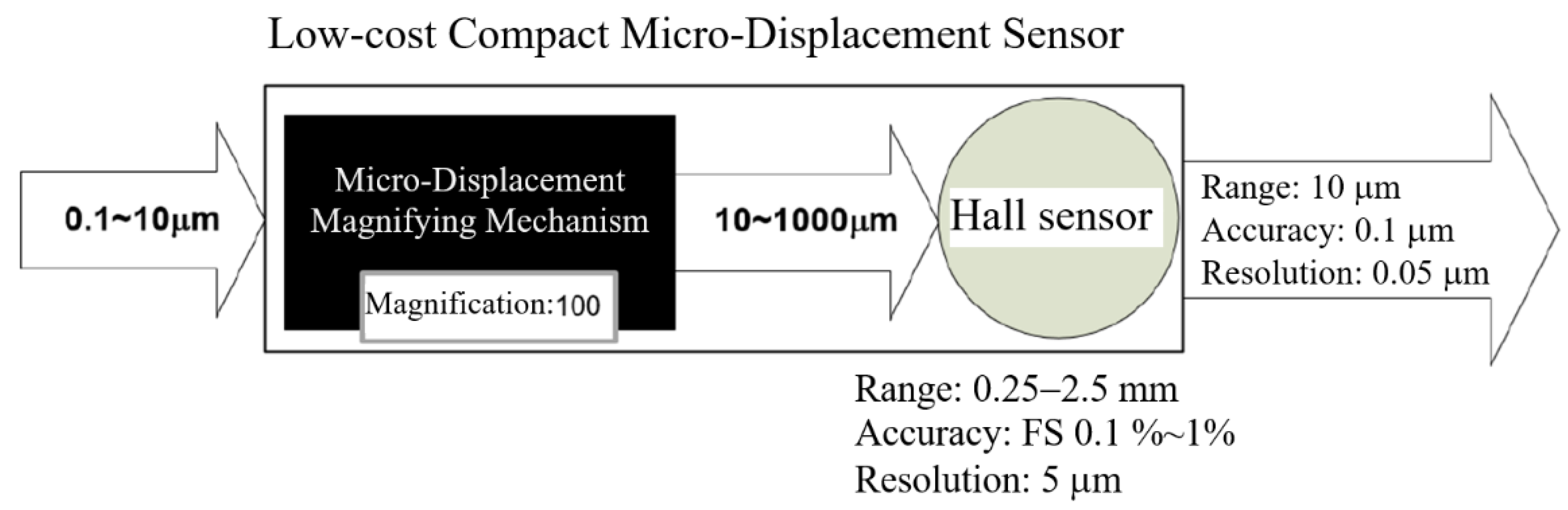
2.1. Basic Concept of the Low-Cost Precision Sensor
2.2. Conceptual Design A: Monolithic Structure of Co-Planar Layout with Monolithic Flexural Joints—Exploratory Study
2.3. Conceptual Design B: Assembled Structure of Multi-Planar Layout with Monolithic Hinges but Flat-Spring Couplers—Exploratory Study
- (1)
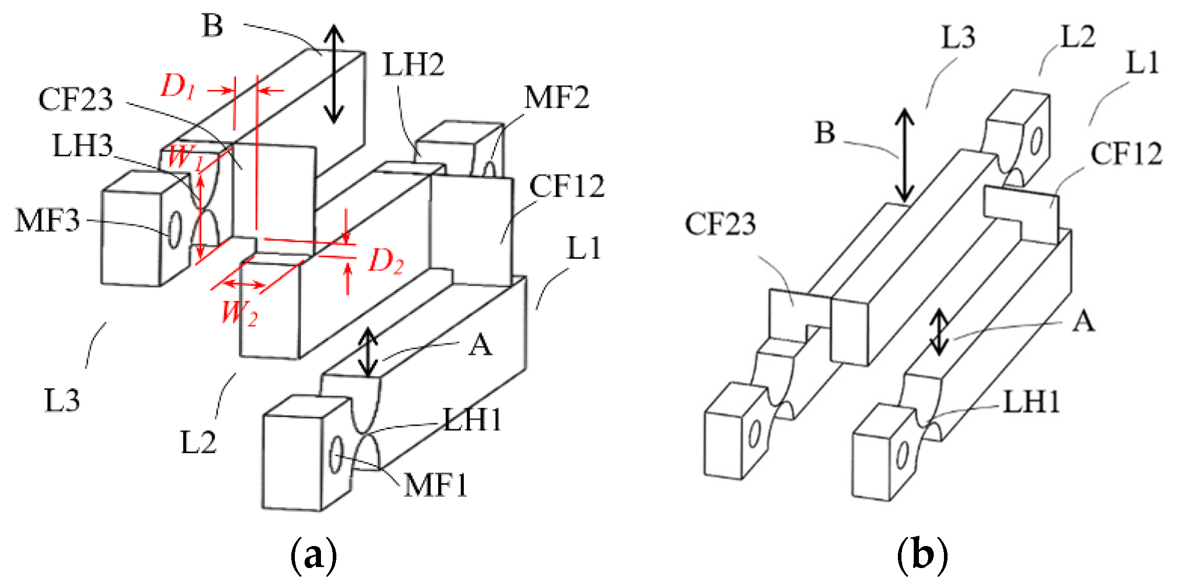
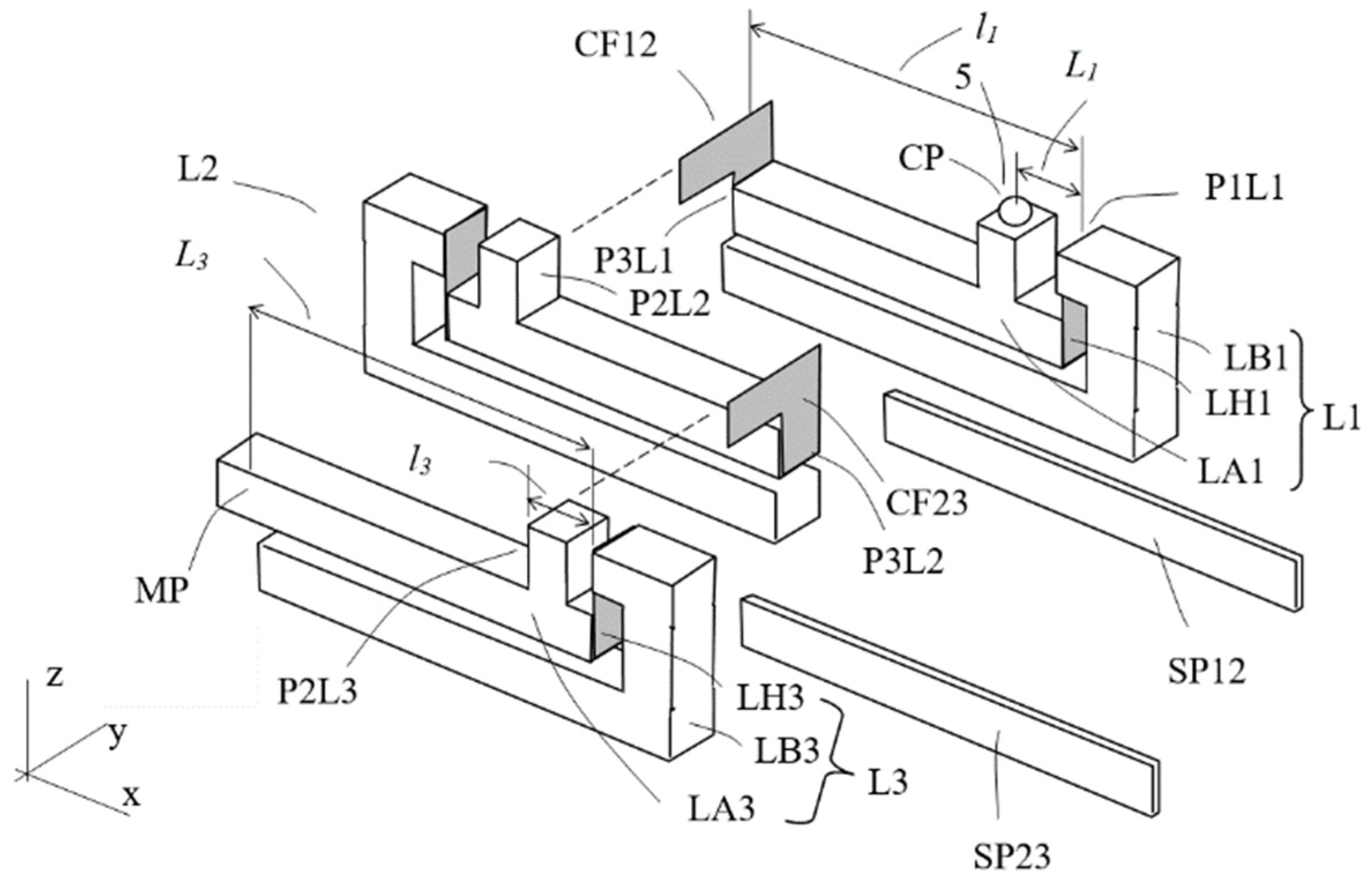
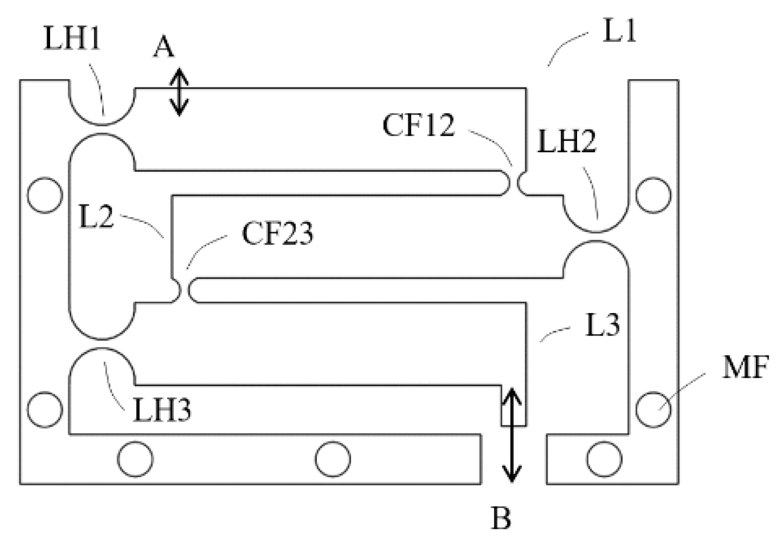
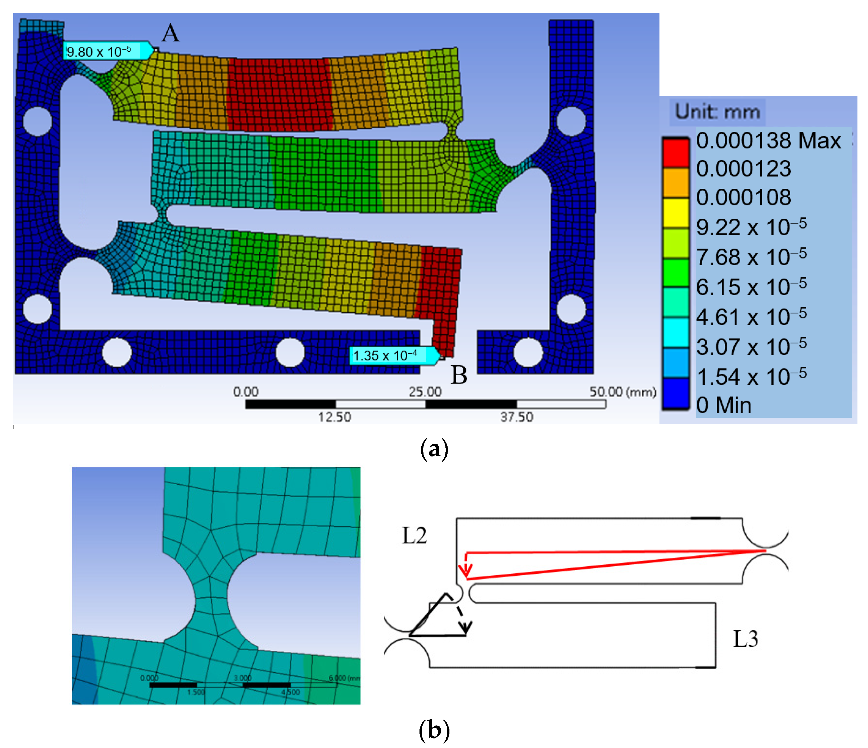
- The coupling foils should be pulled rather than pushed: The first question is in what orientation the L-shaped flat spring foil should be mounted between two adjacent lever arms. In the configuration of Figure 4a, when an input force pushes on position A the output displacement of lever L2 “pulls” lever L3 through the coupling foil CF23; while in the configuration of Figure 4b, lever L2 “pushes” lever L3. Considering mechanics of material, pulling should be preferred because it results in mainly tension, which is easier to take by the coupling foil than pushing, which has a potential of causing bulking in the foil. Finite element simulations using Ansys software confirms this consideration, as a model configuration of Figure 4b gives a smaller magnification ratio than the model configuration of Figure 4a does.
- (2)
- For an assembly of lever structures of a fixed size, the thickness of the coupling foils has a minimal effect on the magnification ratio.
- (3)
- The coupling foils should be in contact with the lever arms with widths as large as possible, as depicted as W1 and W2 in Figure 4a, so that there is sufficient stiffness in the coupling, which helps to improve the magnification ratio.
- (4)
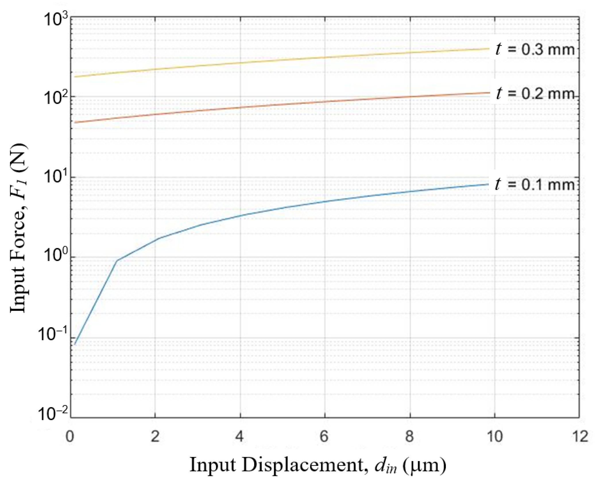
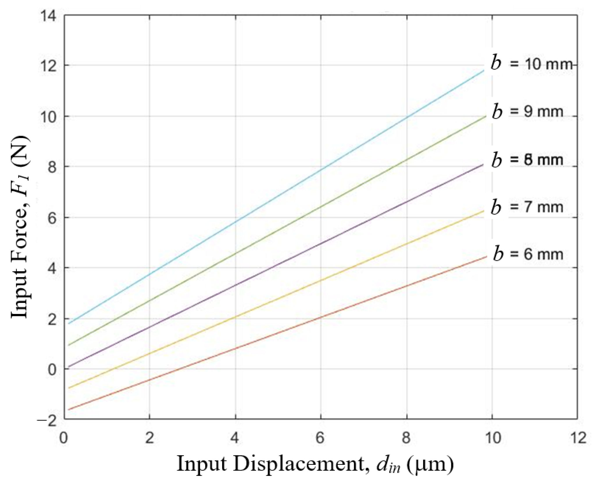
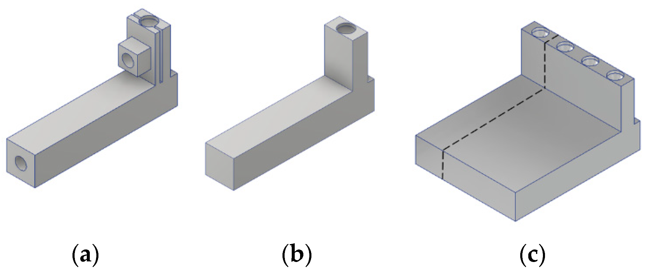
- A larger width (as W2 in Figure 4a) of each lever structure also increases the structure stiffness and thereby helps to improve the magnification ratio. However, activation force also increases with a thicker lever structure. For an input force not exceeding 1 N, the width of the levers in the design of Figure 6a was set to be 8 mm.
- (5)
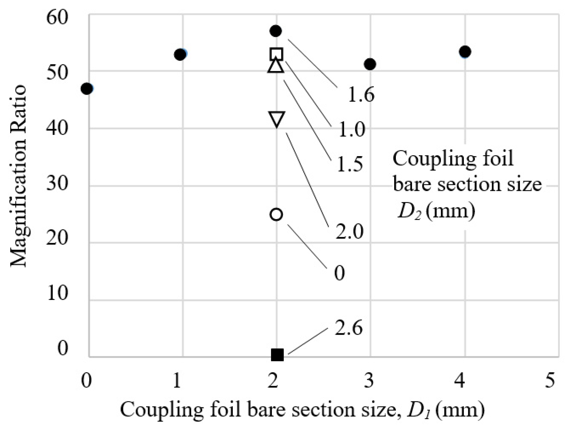
- The sizes of the bare sections of the coupling foil affect achievable magnification ratio significantly, especially the horizontal bare section D2. The bare sections D1 and D2 on the coupling foil are devised to accommodate the relative linear movements and relative rotational movements between adjacent, coupled lever arms. Sizes too small make the cascaded lever structures too stiff to deform, but sizes too large make the coupling too soft to effectively transfer displacement, both hurting the magnification ratio. Therefore, for a cascaded lever structure of a given size, there should be an optimal range of bare section sizes. Different values of D1 and D2 were tested to observe their effects on the total magnification ratio and the results are summarized in Figure 7. D1 = 2 mm and D2 = 1.6 mm were selected as close to optimal for this design.
2.4. Conceptual Design C: Assembled Structure of Multi-Planar Layout with Flat-Spring Couplers but Re-Oriented Monolithic Hinges—Exploratory Study
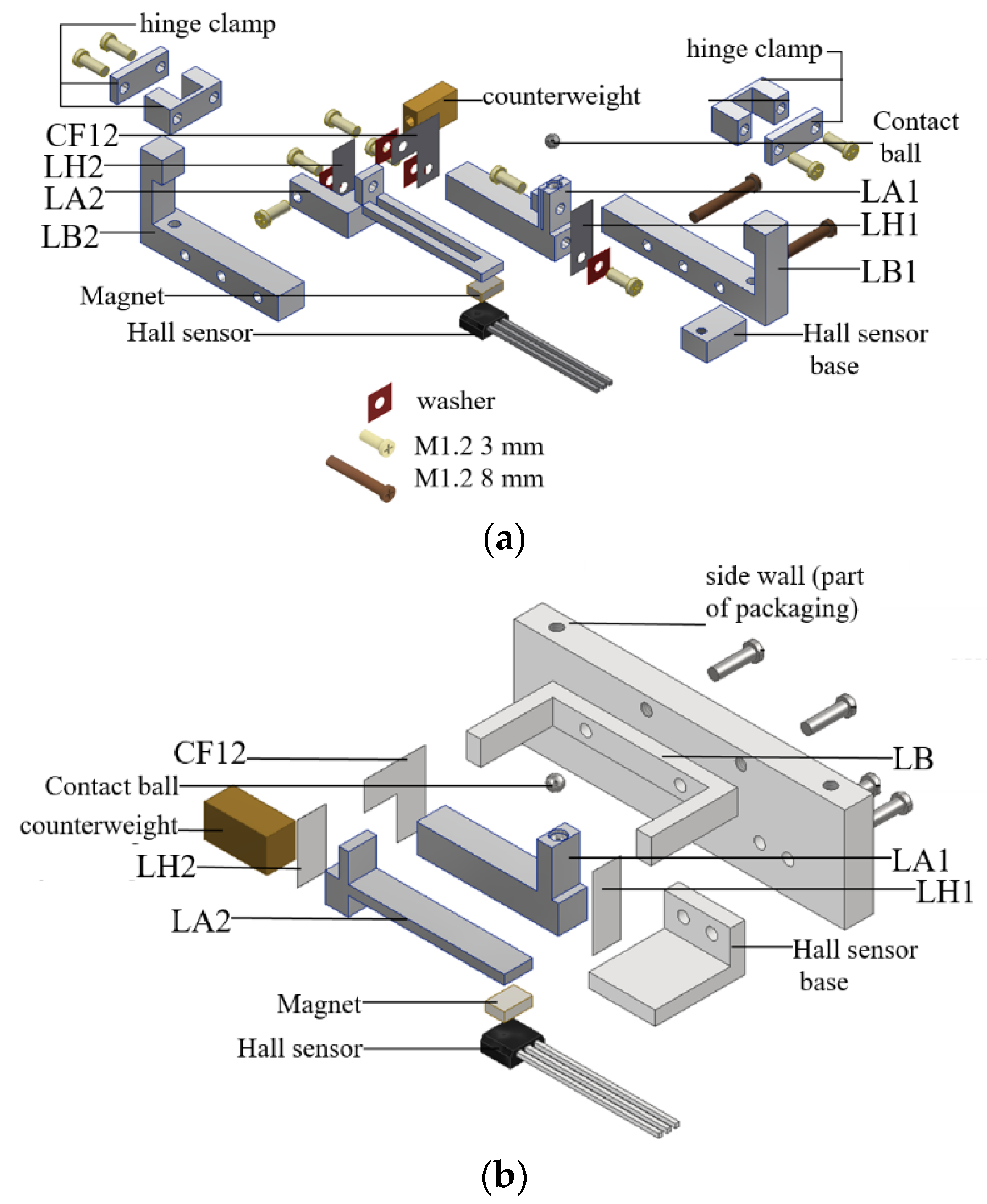
2.5. Conceptual Design D: Assembled Structure of Multi-Planar Layout with Flat-Spring Couplers and Hinges
- A.
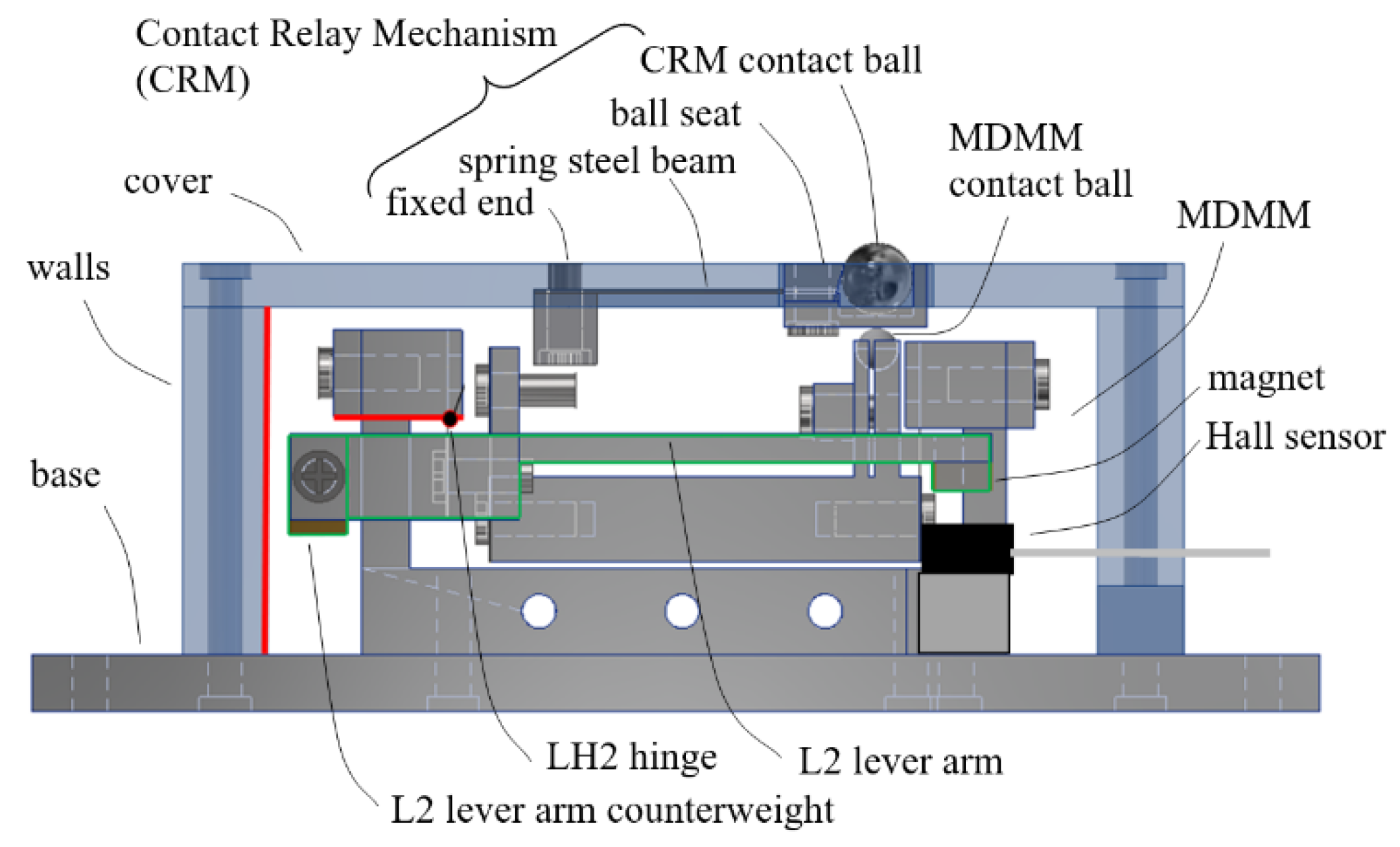
- System layout
- B.
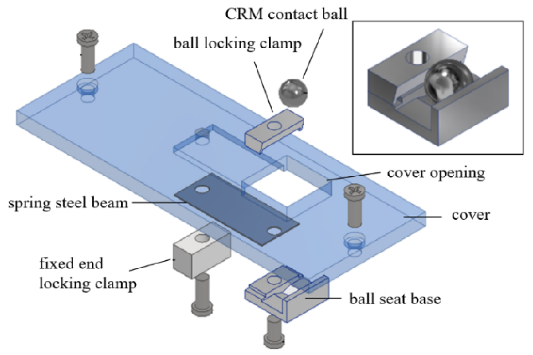
- Design of contact force and the flat spring hinges
3. Prototypes and Tests
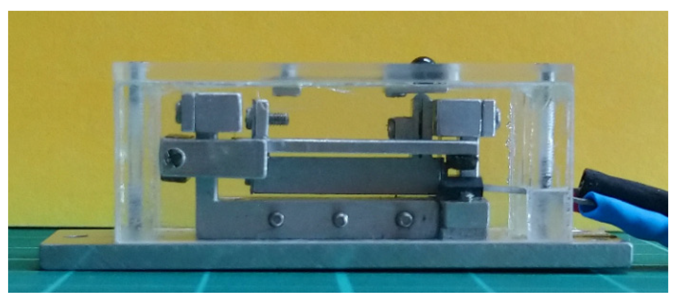
3.1. 82 mm Proof of Concept Prototype
- A.
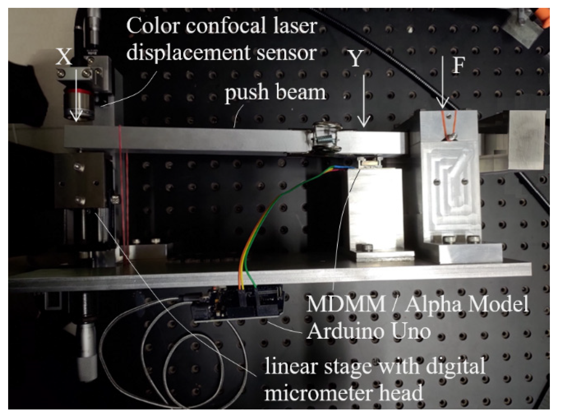
- Measuring prototype output displacement by a second eddy current sensor
- B.
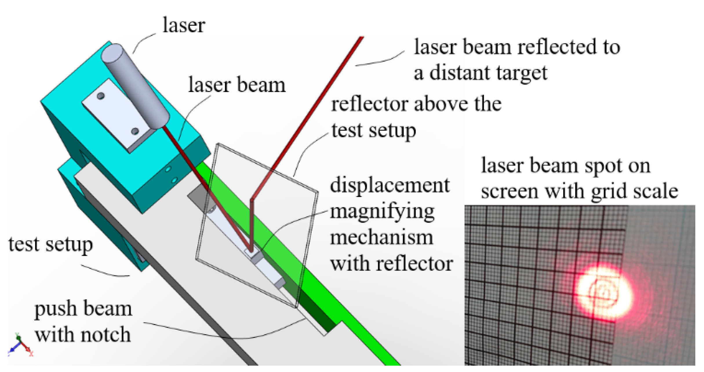
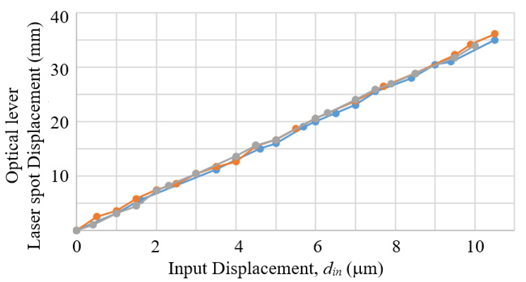
- Measuring prototype output displacement by an optical lever
- C.
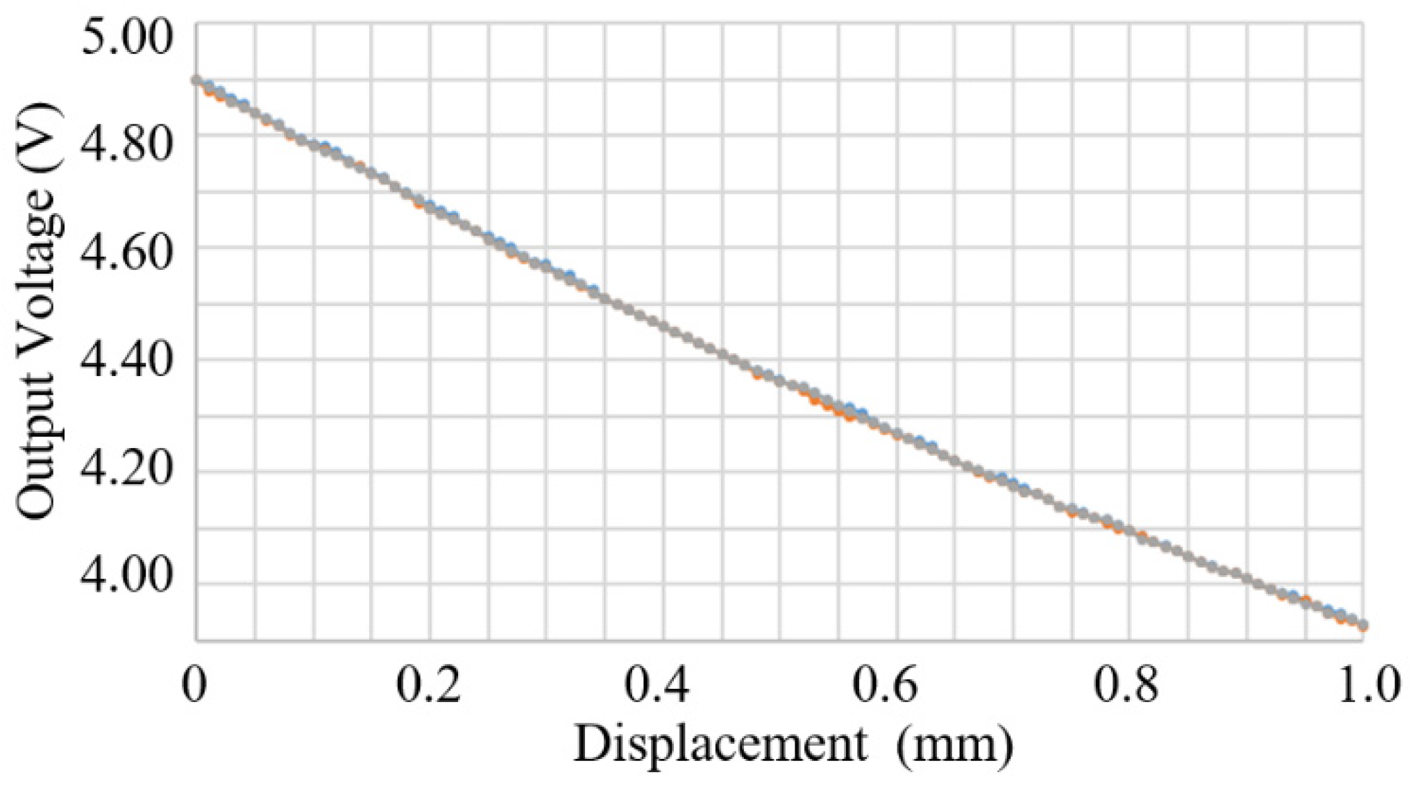
- Measuring prototype output displacement by a Hall sensor
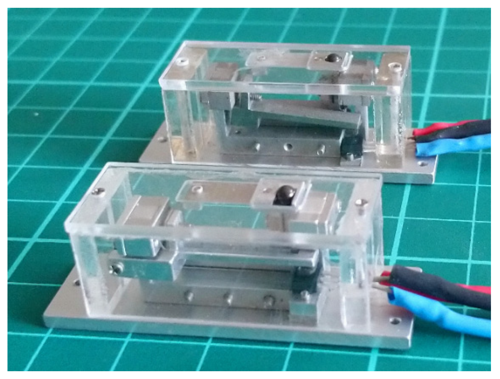
3.2. 25 mm Compact Model
3.3. LCMDS Alpha Model
4. Discussions of Related Issues
4.1. Effect of Variations of Part Dimensions and Assembly Precisions
4.2. Effect of Temperature
4.3. Effect of Magnetic Disturbance
4.4. Design for Low-Cost Small Lot Size Production
5. Conclusions
6. Patents
Author Contributions
Funding
Institutional Review Board Statement
Informed Consent Statement
Data Availability Statement
Acknowledgments
Conflicts of Interest
References
- Micro Epsilon. capaDTCT 6110 Datasheet. Available online: https://www.micro-epsilon.com/download/products/cat-capa/dax-capaNCDT-6110--en.html#page=2&zoom=Fit (accessed on 15 October 2021).
- Kaman. KD-2306 Datasheet. Available online: http://www.kamansensors.com/pdf_files/Kaman_KD-2306_data_sheet_web.pdf (accessed on 15 September 2022).
- Micro Epsilon. InduSensor Catalog. Available online: https://www.micro-epsilon.com/download/products/cat-induSENSOR-en.pdf (accessed on 15 October 2021).
- Micro Epsilon. optoNCDT 1320 Datasheet. Available online: https://www.micro-epsilon.com/download/products/cat-optoncdt/dax-optoNCDT-1320-en.html#page=2&zoom=Fit (accessed on 15 October 2021).
- Keyence. High-Accuracy Digital Contact Sensor GT-2 Series, Product Catalog, Keyence Corporation, 2016.
- Keyence. Color Confocal Laser Displacement Sensor CL-3000 Series, Product Catalog, Keyence Corporation, 2018.
- Slocum, A.H. Precision Machine Design; Prentice-Hall International Inc.: Hoboken, NJ, USA, 1992. [Google Scholar]
- Kelemenová, T.; Dovica, M.; Sedlačko, P. Displacement Amplifying Systems. Acta Mechatron. Int. Sci. J. Mechatron. 2016, 1, 1–5. [Google Scholar]
- Chen, F.; Zhang, Q.; Gao, Y.; Dong, W. A Review on the Flexure-Based Displacement Amplification Mechanisms. IEEE Access 2020, 8, 205919. [Google Scholar] [CrossRef]
- Juuti, J.; Kordás, K.; Lonnakko, R.; Moilanen, V.-P.; Leppävuori, S. Mechanically Amplified Large Displacement Piezoelectric Actuators. Sens. Actuators A 2005, 120, 225–231. [Google Scholar] [CrossRef]
- Muraoka, M.; Sanada, S. Displacement Amplifier for Piezoelectric Actuator based on Honeycomb Link Mechanism. Sens. Actuators A Phys. 2010, 157, 84–90. [Google Scholar] [CrossRef]
- Henmi, N.; Sumi, Y.; Tanaka, M. Fast Drive of Displacement Magnification Mechanism with Flexure hinge using Loading Type Impact Damper. J. Mech. Sci. Technol. 2010, 24, 211–214. [Google Scholar] [CrossRef]
- Yu, Y.; Sung, B.; Yang, W.; Ge, Y. Strain Type Micro-Nano-Scale Micro-Nano Displacement Sensor. CN Patent CN 101435690B, 8 December 2010. (In Chinese, English translation available from Google Patent). [Google Scholar]
- Yamauchi, T. The Annular Multilayer Rock Deformation Testing Device. CN Patent CN 1185580A, 24 June 1998. (In Chinese, English translation available from Google Patent). [Google Scholar]
- Bae, G.H.; Hong, S.W.; Lee, D.W. A Study on Precision Stage with Displacement Magnification Mechanism Using Flexure-Based Levers. Res. J. Appl. Sci. Eng. Technol. 2014, 7, 2225–2231. [Google Scholar] [CrossRef]
- Nada, Y.; Medhat, M.; Nagi, M.; Marty, F.; Saadany, B.; Bourouina, T. Mechanical Displacement Multiplier: 250 μm Stable Travel Range MEMS Actuator Using Frictionless Simple Compliant Structures. In Proceedings of the MEMS 2012, Paris, France, 29 January–2 February 2012; p. 1161. [Google Scholar]
- Merken, P.; Smal, O.; Debongnie, J.; Raucent, B. Mechanical Based Circular Notch Hinge Design. January 2007. Available online: https://www.researchgate.net/publication/277065173_Mechanical_based_circular_notch_hinge_design (accessed on 15 September 2022).
- ISO 230-2: 2014(E); Test Code for Machine Tools—Part 2: Determination of Accuracy and Repeatability of Numerically Controlled Axes. ISO: Geneva, Switzerland, 2014.
- Anonymous. SANDVIK Precision Strip Steel, SANDVIK, Application Note. 2019. Available online: https://www.materials.sandvik/globalassets/global/downloads/products_downloads/strip-steel-and-strip-based-products/sandvik-precision-strip-brochure-19-0863.pdf (accessed on 15 September 2022).
- Tsao, C.C.; Tseng, Y.C. Low-Cost Compact Micro-Displacement Sensor. U.S. Patent 16/677,174, 7 December 2019. Counterpart in Taiwan: Taiwan Patent 109138905, 6 December 2020. [Google Scholar]
- Tsao, C.C. Low-cost Compact Micro-Displacement Sensor. CN Patent 202210474163.8, 29 April 2022. [Google Scholar]


| Category | Range (mm) | Accuracy (μm) | Resolution (μm) | Dealer Price in USD a (Brand/Manufacturer) |
|---|---|---|---|---|
| Capacitive sensor | 0.05 | 0.15 | 0.001 | $2000 (με) b |
| Eddy current sensor | 1 | 1 | 0.1 | $2100 (Kaman) c |
| Inductive sensor (LVDT) | 1 | 6 | -- i | $650 (με) d |
| Laser triangulation | 10 | 12 | 1 | $1300 (με) e |
| Digital contact displacement sensor | 12 | 1 | 0.1 | $1600 (Keyence) f |
| Color confocal laser displacement sensor | 7 | 0.94 | 0.25 | >$8000 (Keyence) g |
| Hall sensor | 0.25–2.5 | 0.1~1% of full scale | 5 | $5 h |
| Measurement Range (μm) | Magnification Ratio | Magnified Measurement Range (mm) | Accuracy (μm) | Resolution (μm) |
|---|---|---|---|---|
| 10 | 250 | 2.5 | 0.01–0.1 | 0.002–0.02 |
| 10 | 100 | 1 | 0.01–0.1 | 0.005–0.05 |
| 25 | 100 | 2.5 | 0.025–0.25 | 0.005–0.05 |
| 50 | 50 | 2.5 | 0.05–0.5 | 0.01–0.1 |
| 100 | 25 | 2.5 | 0.1–1 | 0.02–0.2 |
| 250 | 10 | 2.5 | 0.25–2.5 | 0.05–0.5 |
| 500 | 5 | 2.5 | 0.5–5 | 0.1–1 |
| Alpha Model | Repeatability (μm) | Accuracy (μm) | Resolution (μm) |
|---|---|---|---|
| Erected orientation | 0.20 | 0.42 | 0.03 |
| Horizontal orientation | 0.54 | 0.36 | 0.04 |
Disclaimer/Publisher’s Note: The statements, opinions and data contained in all publications are solely those of the individual author(s) and contributor(s) and not of MDPI and/or the editor(s). MDPI and/or the editor(s) disclaim responsibility for any injury to people or property resulting from any ideas, methods, instructions or products referred to in the content. |
© 2022 by the authors. Licensee MDPI, Basel, Switzerland. This article is an open access article distributed under the terms and conditions of the Creative Commons Attribution (CC BY) license (https://creativecommons.org/licenses/by/4.0/).
Share and Cite
Tsao, C.-C.; Tseng, Y.-C.; Chen, Y.-S.; Chang, W.-H.; Huo, L.-T. Precision Low-Cost Compact Micro-Displacement Sensors Based on a New Arrangement of Cascaded Levers with Flexural Joints. Sensors 2023, 23, 326. https://doi.org/10.3390/s23010326
Tsao C-C, Tseng Y-C, Chen Y-S, Chang W-H, Huo L-T. Precision Low-Cost Compact Micro-Displacement Sensors Based on a New Arrangement of Cascaded Levers with Flexural Joints. Sensors. 2023; 23(1):326. https://doi.org/10.3390/s23010326
Chicago/Turabian StyleTsao, Che-Chih, Yi-Chun Tseng, Yu-Sheng Chen, Wei-Hsuan Chang, and Li-Ting Huo. 2023. "Precision Low-Cost Compact Micro-Displacement Sensors Based on a New Arrangement of Cascaded Levers with Flexural Joints" Sensors 23, no. 1: 326. https://doi.org/10.3390/s23010326
APA StyleTsao, C.-C., Tseng, Y.-C., Chen, Y.-S., Chang, W.-H., & Huo, L.-T. (2023). Precision Low-Cost Compact Micro-Displacement Sensors Based on a New Arrangement of Cascaded Levers with Flexural Joints. Sensors, 23(1), 326. https://doi.org/10.3390/s23010326