1. Introduction
Lens system imaging is used to obtain information about a target, and extending the imaging spectrum is an important way of obtaining more information. Refractive lens systems [
1,
2,
3] used in the broadband UV range are often designed with multiple lenses or by using coated prisms to ensure the lens system meets the requirements for broadband operation. However, the low UV transmittance of glass reduces the overall transmission rate of the refractive lens system, and the use of prisms increases the weight of the lens system and the difficulty of installation, which is not conducive to fabricating a lightweight miniaturized lens system. Although reflective optical systems [
4,
5] can meet the requirements of UV broadband operation, their field of view is limited to a small range of object heights and 0.8°. Current designs of hybrid refractive/diffractive lens systems [
2,
6,
7,
8] with single-layer diffractive optical element (DOE) in the UV band are only applicable to narrow wavelengths. This narrow operating band notwithstanding, the introduction of single-layer DOE into a lens system provides an ideal way to achieve lightweight miniaturized UV wide-spectrum large-field lens systems.
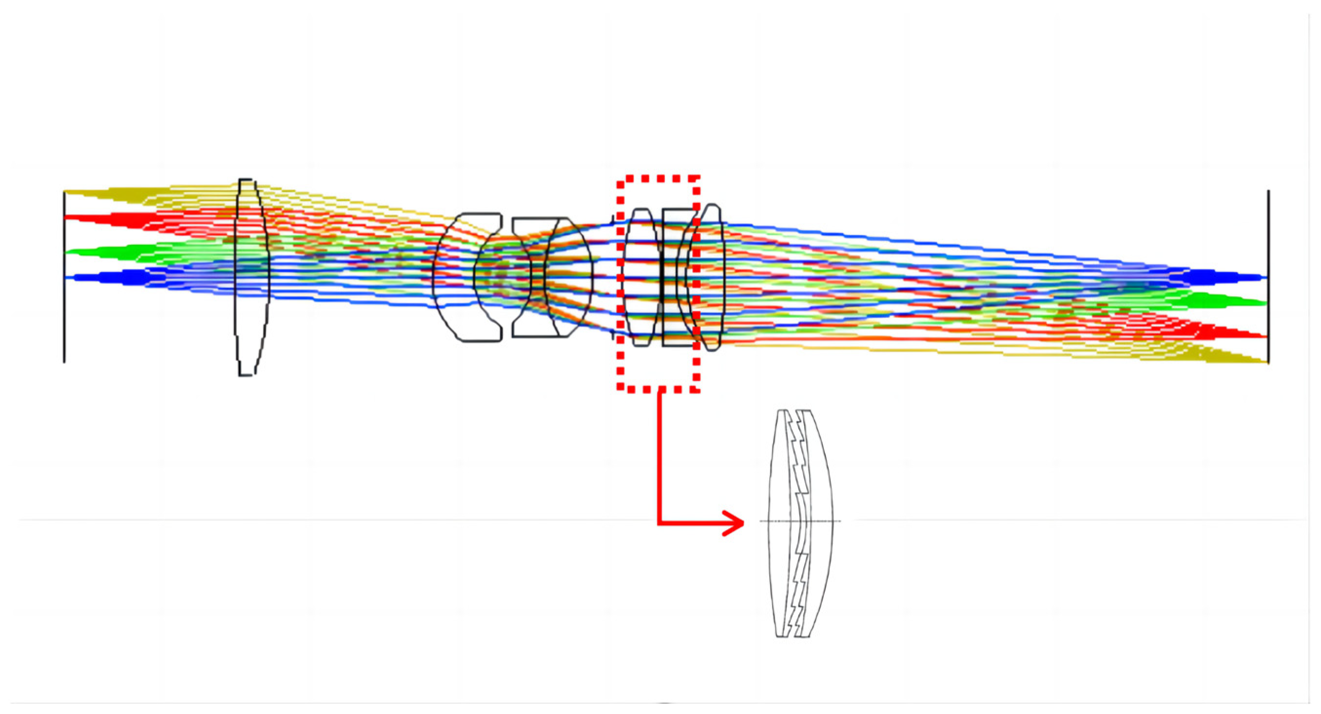
Double-layer DOEs are more suitable for broad bands than single-layer DOE and can be used in lens systems to meet the requirements of the UV broad-spectrum large field-of-view operation and realize lighter miniaturized lens systems. In this study, we analyze and optimize the bandwidth integration average diffraction efficiency (BIADE) of double-layer DOEs in the 0.23–0.8 μm band and fabricate a substrate material for double-layer DOEs for use in a lens system. The performance of a UV broad-spectrum refractive/diffractive hybrid lens system with double-layer DOEs (as shown in
Figure 1 below) is compared with that of the traditional refractive lens system. The double-layer-DOE hybrid system outperforms the refractive system. The feasibility of using double-layer DOEs in UV broad-spectrum lens systems provides a means of miniaturizing a lightweight system.
2. Analysis and Optimization of Double-Layer Diffractive Optical Elements for a Broad Ultraviolet Spectrum
The diffraction efficiency of a single-layer DOE is 100% only at the design wavelength. As the diffraction efficiency drops rapidly at wavelengths other than the design wavelength, a nonworking-order diffraction beam can cause the contrast ratio in the imaging plane to decrease; thus, the single-layer DOEs that are primarily used in the lens systems operate within a narrow waveband. In contrast, double-layer DOEs are based on different dispersive materials and different surface relief heights. Double-layer DOEs can be an effective means of achieving high diffraction efficiency in wide wavebands. A schematic of a double-layer DOE is shown below.
For a parallel beam that is vertically incident on a double-layer DOE (angle of incidence
), the m-order diffraction efficiency (
) can be determined using Equation (1), as follows [
9]:
where
and
are the refractive indexes of the two DOEs at the wavelength
, and
and
are the corresponding microstructure heights, as shown in
Figure 2b.
The BIADE of DOEs operating in a specific waveband range is
where
and
denote the minimum and maximum wavelength values in the operating band range of DOEs, respectively.
The following relationship holds for two different dispersion materials and two design wavelengths,
and
, in the dual design band.
The diffraction efficiency of a double-layer DOE is not uniformly distributed over the entire waveband and must therefore be optimized. The diffraction efficiency at long wavelengths needs to be equal to that at short wavelengths, as follows:
Combining Equations (1) and (4) yields
Substituting relevant data into Equation (5) yields a relationship between d
2 and d
1. m = +1; generally, the +1 order diffraction beam is taken as the imaging beam. Commonly available materials with high transmittance in the wavelength range of 0.23–0.8 μm and facile processability include SiO
2, CaF
2, and MgF
2, of which any two can be combined for use as a DOE substrate. The microstructure height is a major parameter for DOE processing. When using Equation (3) to estimate the material dispersion coefficients, two materials with highly similar Abbe numbers make the denominator small, which leads to a large microstructure height, d
1. A large microstructure height for multilayer DOEs makes processing difficult and leads to a low diffraction efficiency [
10,
11]. Therefore, the similar dispersion coefficients of CaF
2 and MgF
2 led to the exclusion of this combination of glasses for substrate fabrication. Substituting the aforementioned relationship between d
1 and d
2 into Equations (1) and (2) yields the relationship between the microstructure height d
1 and BIADE of double-layer DOEs, as shown in
Figure 3 for three substrates of different material pairs.
The optimization process yielded a combined microstructure height of −27.57 μm for CaF
2 and SiO
2 and −24.27 μm for MgF
2 and SiO
2 for a 100% diffraction efficiency.
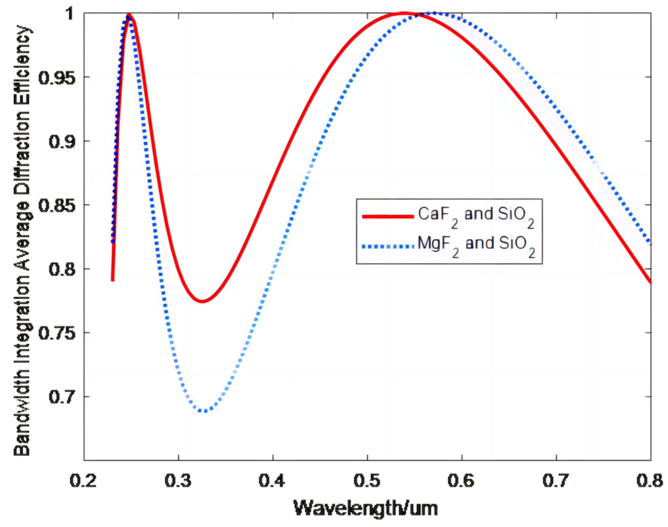
Figure 4 shows the relationship between the wavelength and BIADE obtained for three substrates consisting of different material combinations for the optimized double-layer DOEs.
Figure 4 shows that the highest BIADE in the wavelength range of 0.23–0.8 μm of the double-layer DOE is obtained using a substrate consisting of CaF
2 and SiO
2. Therefore, CaF
2 and SiO
2 were chosen as the substrate materials for the subsequent design of double-layer DOEs.
The previous analysis was based on orthogonal incidence, where the heights of the two optimized microstructures were found to be and , respectively. Next, we consider the effect of the angle of incidence on the diffraction efficiency in the case of oblique incidence.
For a light beam that is obliquely incident on a double-layer DOEs substrate (that is, the angle of incidence
), the diffraction efficiency is related to the microstructure heights, angle of incidence, waveband, and material refractive properties, as follows [
12]:
CaF
2 and SiO
2 are selected for the first and second slice materials, respectively. Air is selected as an intermediate medium material (
), and the reference wavelengths are taken as
.
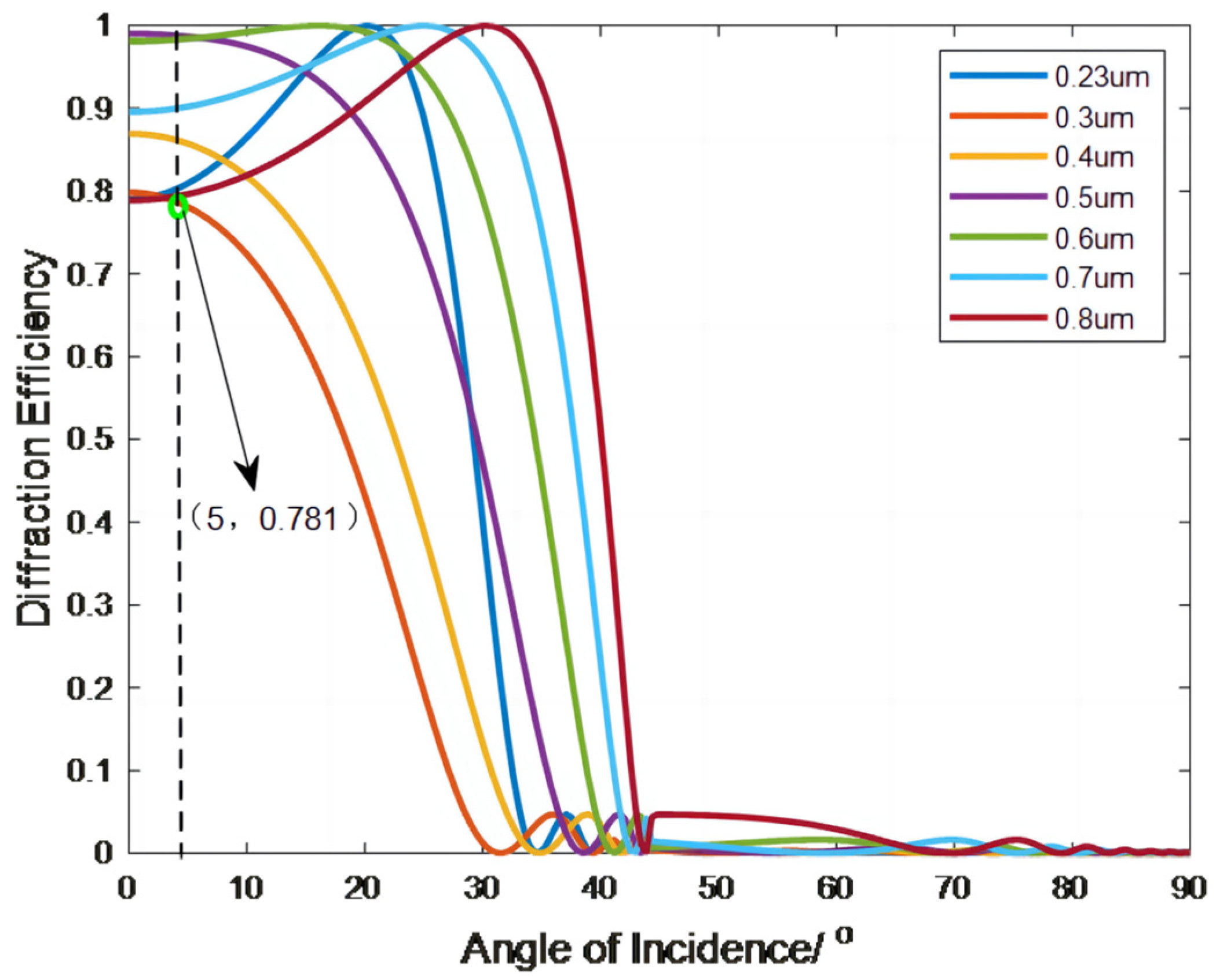
Figure 5 shows the diffraction efficiency of the double-layer DOE versus the angle of incidence.
Figure 5 shows that the double-layer DOE diffraction efficiency is lowest at
and decreases as the angle of incidence increases; for angles of incidence that do not exceed 5°, the diffraction efficiency remains above 78.1%. For angles of incidence exceeding 5°, the diffraction efficiency decreases sharply and drops to 0 at an incidence angle of 30°. This result provides a constraint on the subsequent optical design. To ensure a reasonable diffraction efficiency for the double-layer DOE used in a lens system, the angle of incidence of the light on the lens surface should be controlled to within 5°.
3. UV Broad Spectrum Achromatic Lens System Design
The specifications of the design parameters of the lens system are provided in
Table 1 below.
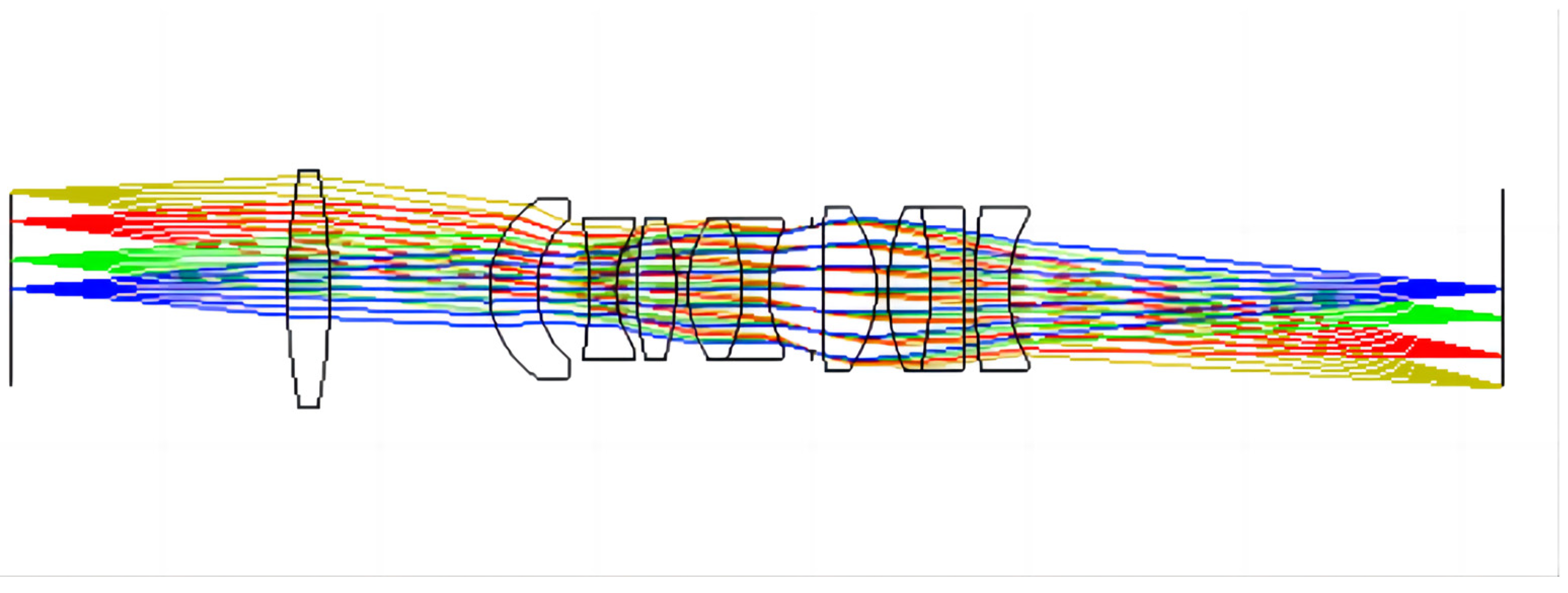
To ensure the MTF of 30 lp/mm is higher than 0.1 at all wavelengths, the final refractive lens system design consisted of 10 lenses. A diagram of the final optimized structure is shown in
Figure 6.
Using double-layer DOEs in refractive lens systems reduces the number of lenses, improves light transmission by the lens system, and facilitates the fabrication of a lightweight miniaturized lens system. Diffractive surfaces are added to the rear surface of the fifth lens and the front surface of the sixth lens, with CaF
2 and SiO
2 as the substrate materials. The angle of incidence of the light affects the diffraction efficiency of double-layer DOEs. In this design, it is necessary to control the incidence angle of the central and edge rays of light on the first slice layer of the double-layer DOEs so that they are 0. The radius of curvature of the lens results in an incident angle for the final edge light on the first substrate of 4.453°, where the diffraction efficiency of the double-layer DOEs at 0.3 μm is higher than 80.54%.
Figure 7 shows the structure of the final lens system with seven lenses. The lens data of the refractive/diffractive hybrid lens system are shown in
Table 2 and
Table 3.
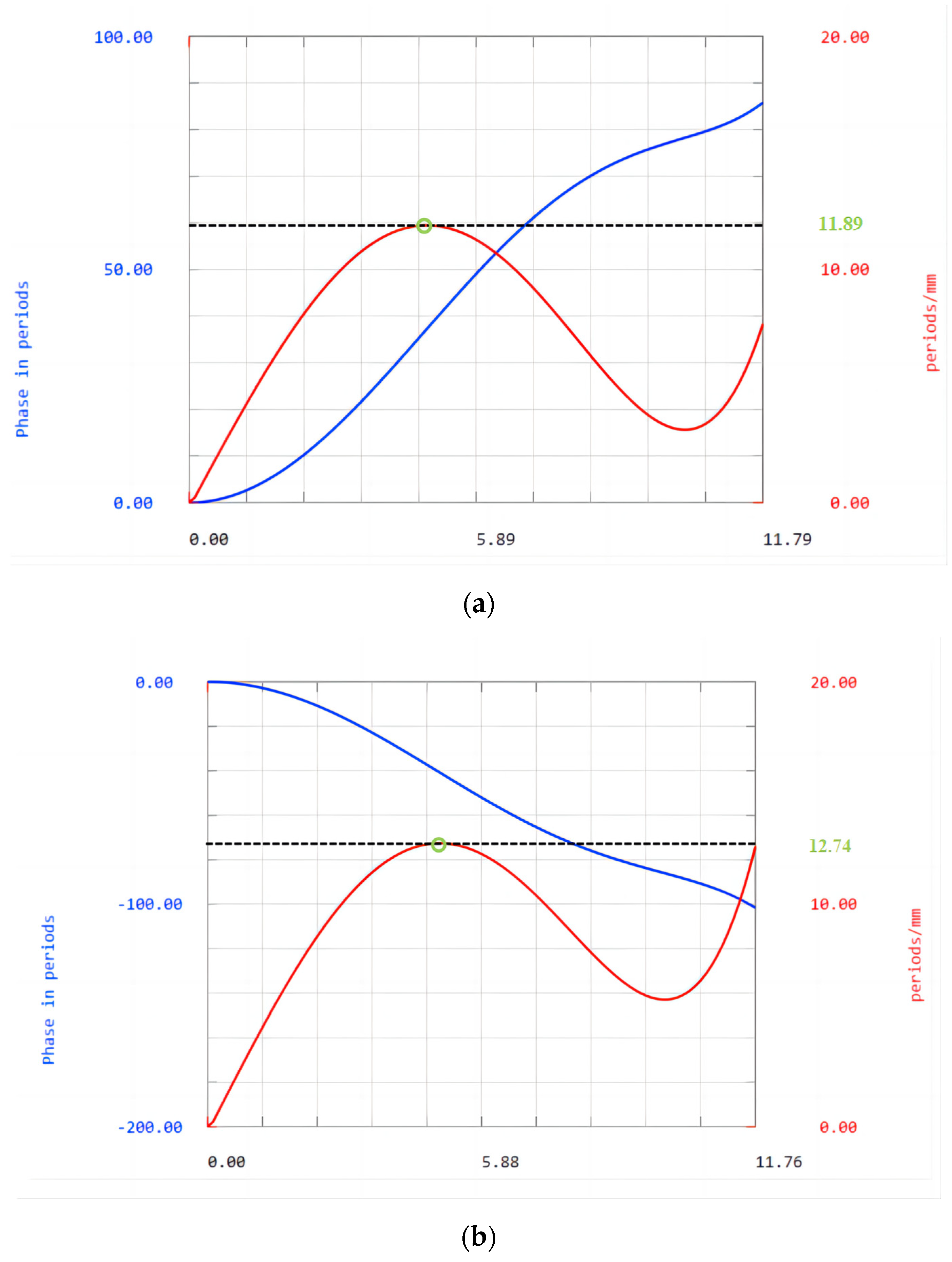
Figure 8 shows a phase plot of the diffractive surface. The abscissa is the diameter; the blue curve represents the additional phase introduced by the binary surface, and the unit is the period; the red curve represents the change of phase at different net diameters (contour frequency), and the unit is cycle per millimeter. The diffractive surfaces with CaF
2 as substrate have a maximum of 11.89 cycles per millimeter of the ring band, the reciprocal of which corresponds to a minimum cycle width of
. The diffractive surfaces with SiO
2 as the substrate have a maximum of 12.74 cycles per millimeter of the ring band, the reciprocal of which corresponds to a minimum cycle width of
. The minimum period width of the binary surface used in this study meets the processing requirements. Both binary surfaces can be processed.
The design results for the two lens systems are presented in the figures below.
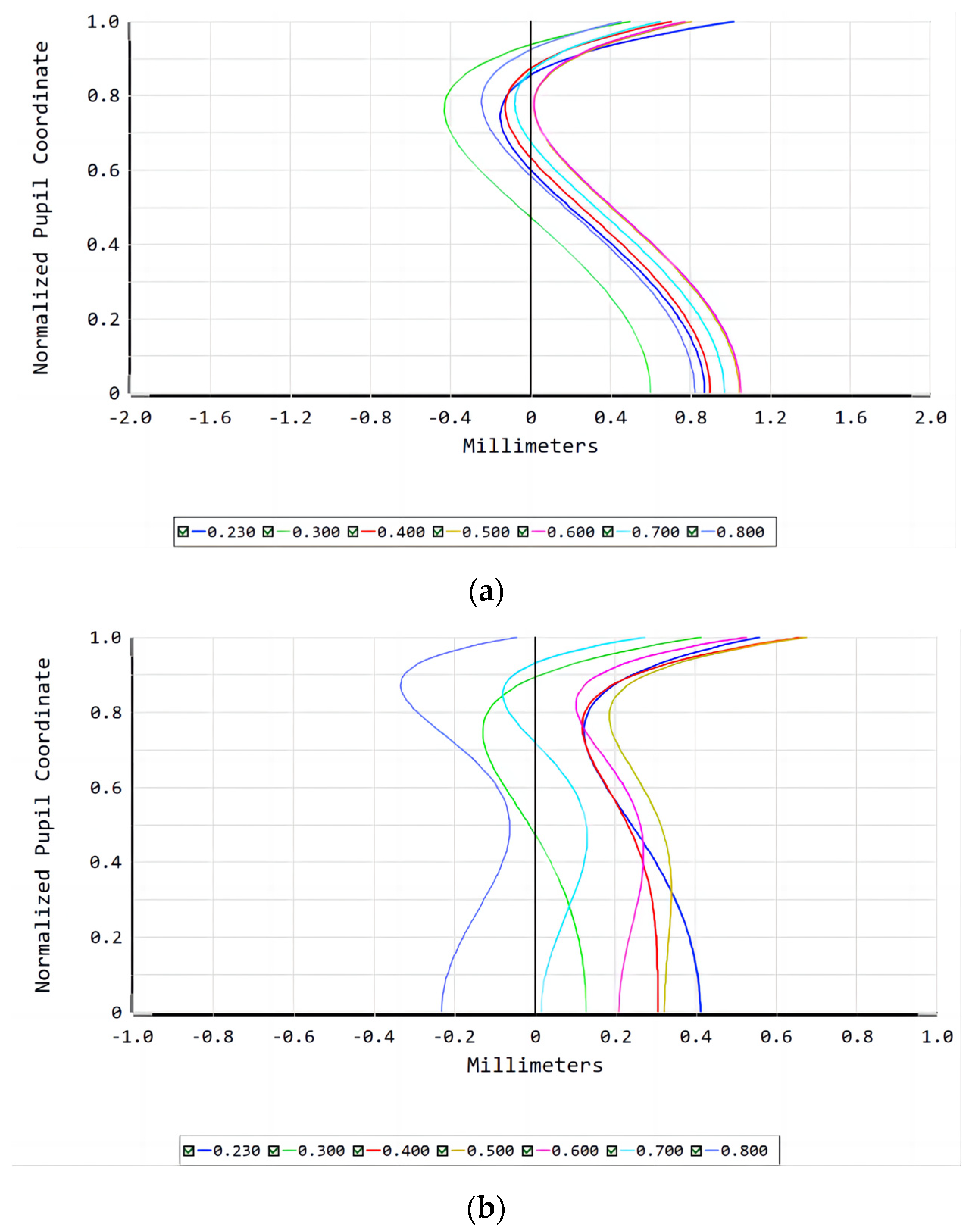
Figure 9 shows the correction of chromatic aberration for the refractive lens and refractive/diffractive hybrid lens systems: the positional chromatic aberration of the refractive/diffractive hybrid lens system is less than 0.4 for an aperture of 0 and less than 1 for an aperture of 1. The positional chromatic aberration for an aperture of 0.7 is less than 0.4.
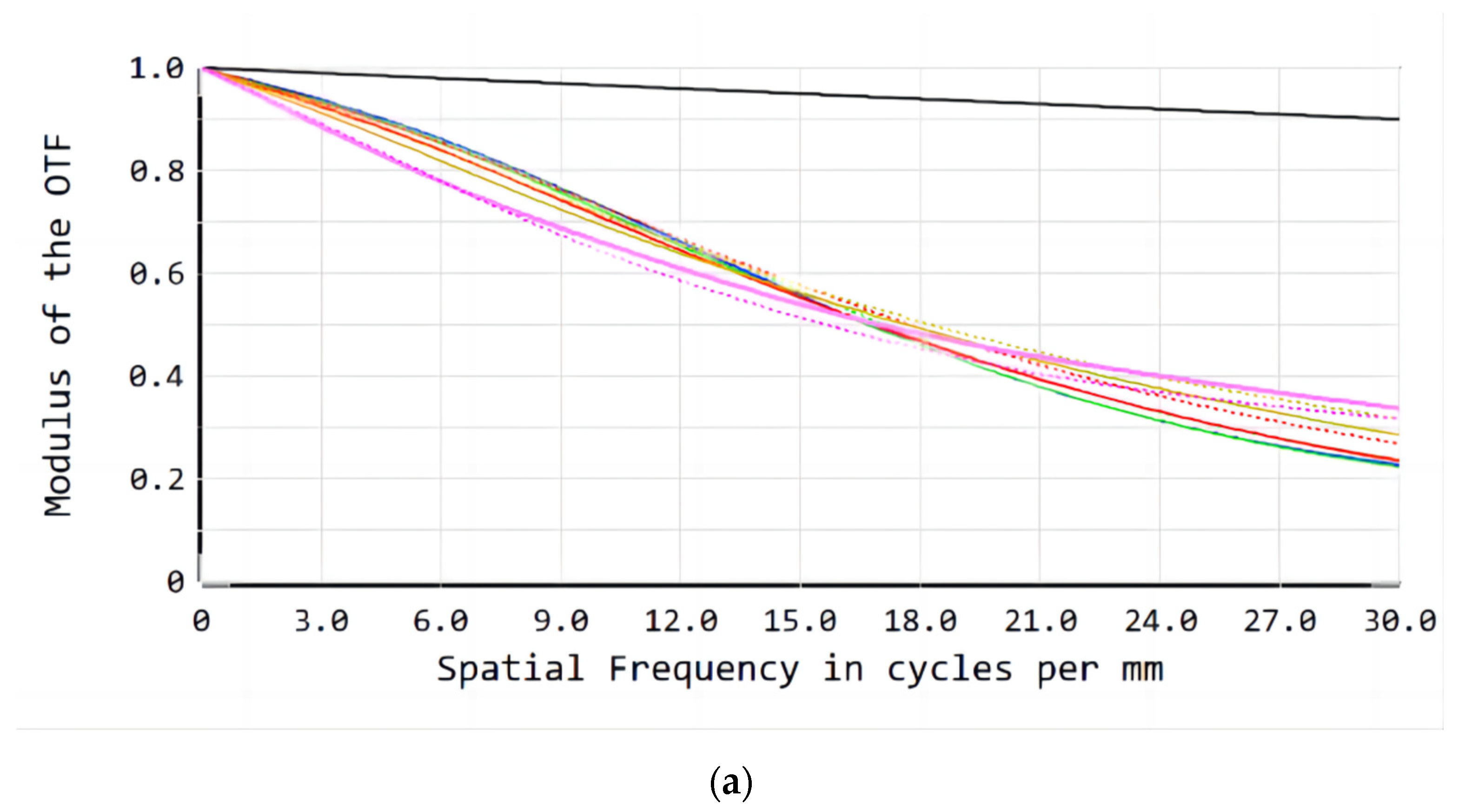
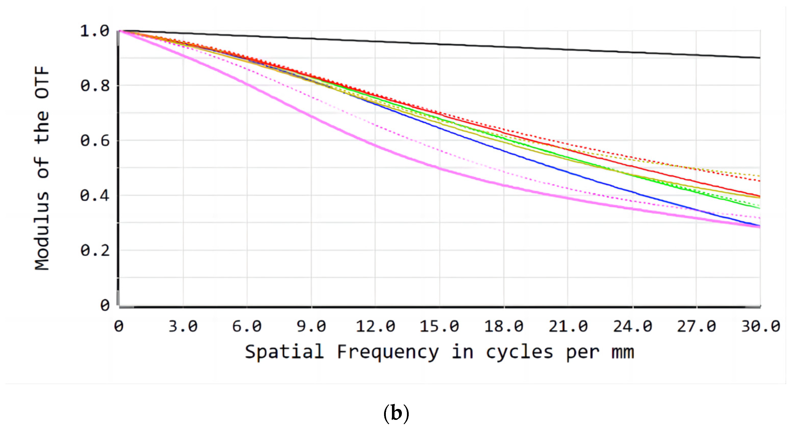
Figure 10 shows the imaging quality results. The MTF of the refractive/diffractive hybrid lens system reaches more than 0.3 at 30 lp/mm and is higher than that of the refractive lens system.
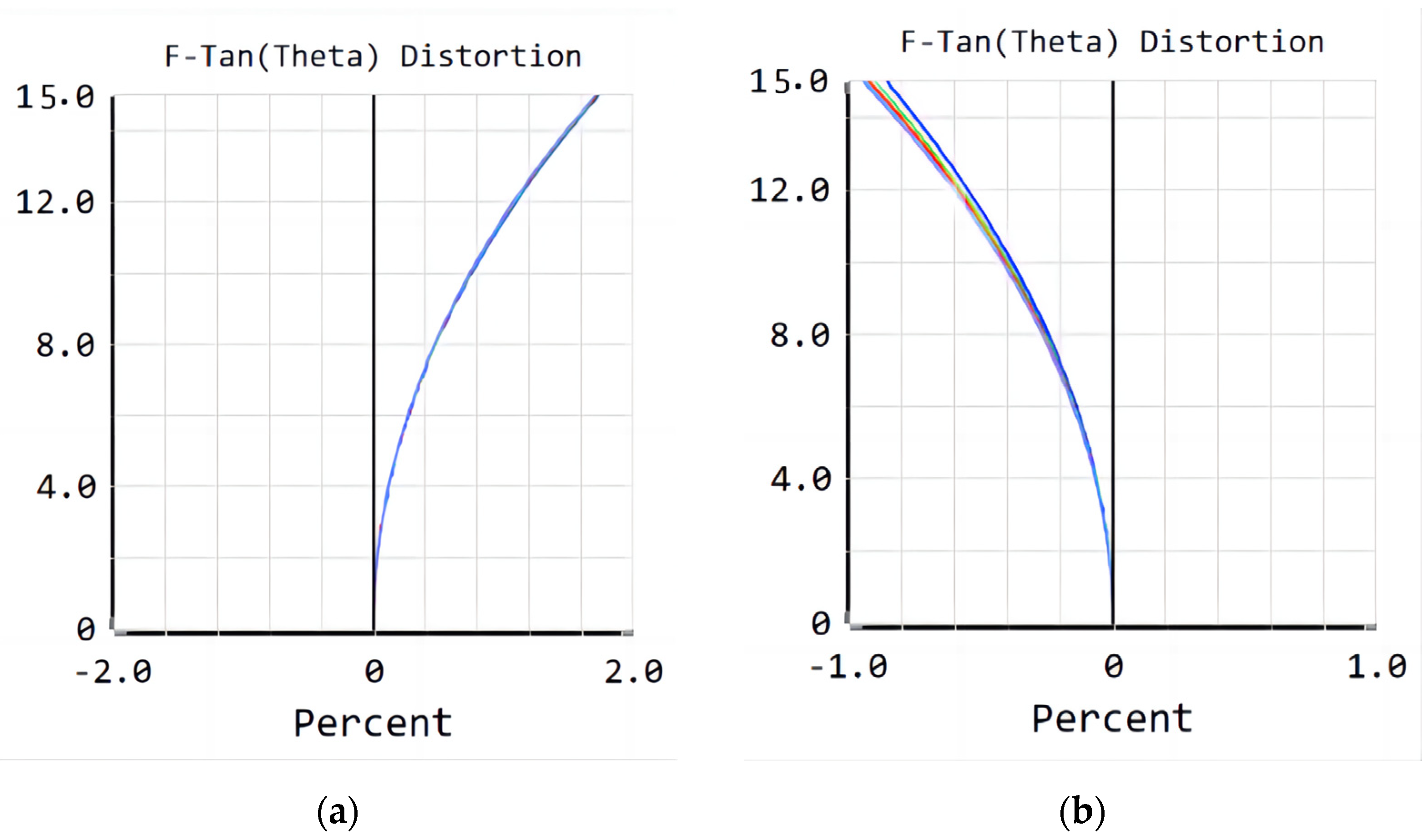
Figure 11 shows that the maximum distortion of the refractive/diffractive hybrid lens system is −0.95% and the imaging distortion is smaller than that of the refractive lens system during use. The design results show that the optical performance of the refractive/diffractive hybrid lens system is higher than that of the refractive lens system.
According to the data [
13], the transmittance at
is 90.61% for 10-mm SiO
2, 92.06% for 10-mm CaF
2 and 93.95% for 10-mm MgF
2. The transmittance of the entire system for the final lens design can be calculated based on the thickness of each lens. The overall transmittance of the refractive lens system is 59.59%. In the final design of the refractive/diffractive hybrid lens system, the incidence angle of light on the first layer of the double-layer DOEs is 4.453°, the minimum diffraction efficiency of the double-layer DOEs is 80.54%, and the overall transmittance of the system is 57.63%. Compared to the refractive lens system, the refractive/diffractive hybrid lens system designed with seven lenses is lighter, simpler and achieves nearly the same transmittance.


