Article

Design, Manufacture, Test and Experiment of Six-Axis Force Torque Sensor for Chinese Experimental Module Manipulator

1
State Key Laboratory of Robotics and System, Harbin Institute of Technology, Harbin 150001, China
2
School of Mechatronics Engineering, Harbin Institute of Technology, Harbin 150001, China
Sensors 2022, 22(9), 3603; https://doi.org/10.3390/s22093603
Submission received: 15 March 2022 / Revised: 29 April 2022 / Accepted: 5 May 2022 / Published: 9 May 2022
(This article belongs to the Topic Space Robotics)

Abstract

:
A novel six-axis force/torque sensor (F/T sensor) for an Experimental Module Manipulator (EMM) in the Chinese Space Station (CSS) is developed in this paper. First, we designed the elastomer structure of the F/T sensor and used the analytical method and the finite element method to analyze the strain, in order to accomplish the strain gauges’ layout. Then, the electrical system was designed, which mainly realizes the acquisition of force/torque information, temperature and serial communication with the end effector (EE). Following this, we analyzed and designed the adaptability of the F/T sensor to the space environment. After this, the manufacturing process of the sensor was introduced in detail, and the F/T sensor was calibrated by a pulley weight system. Finally, the sensor was tested on the space environment adaptability of mechanical vibration and thermal vacuum on the ground. The test results show that the developed sensor has the ability to accurately measure three-dimensional force and three-dimensional moment information on orbit, which provides necessary conditions for the on-orbit fine operation of EMM.

1. Introduction

The Chinese Space Station (CSS) will be constructed in 2022. It includes one core module (CM), two experimental modules (EM) and one cargo spaceship [1]. The space manipulators will play significant roles in completing space tasks, such as on-orbit assembly, maintenance, manipulation assistance, payload care and astronaut on-orbit support. So far, these space manipulators have been developed for the International Space Station (ISS). They are the Space Station Remote Manipulator System (SSRMS), designed by the Canada Space Agency (CSA), the Japanese Experimental Module Remote Manipulator System (JEMRMS), devised by the Japan Aerospace Exploration Agency (JAEA), and the European Robotic Arm (ERA), developed by the European Space Agency (ESA) for the Russian module [2,3,4]. Moreover, the space manipulator for the CM of the CSS launched in 2021.
The existing space manipulators have an obvious significant feature—all of them equipped the six-axis force/torque sensor (F/T sensor). This sensor could measure the force/torque information when the end effector contacts the environment or grasps payloads in the space station. Taking advantage of the force/torque information, the space manipulator will complete a series of complicated and fine work, and consequently, realize the intelligence.
The CSS has two space manipulators, with the big one installed on the CM and the small one will be located on the EM. The small manipulator, namely Experimental Module Manipulator (EMM), which can work independently on the EM to look after exposed experimental and optical platforms, checks the modules and accomplishes EVA support. For enhancing the force control capability of the space manipulator, the F/T sensor should be configured. The F/T sensor is an important part, which is used to sense the contact multi-dimensional force/torque information during the EMM’s operating load process, and provide a basis for the EMM’s impedance control or compliance force control. If the space manipulator does not have the F/T sensor, it will greatly weaken the capability of the space manipulator when it is necessary to interact with the environment. Different from the common F/T sensor on the ground [5,6,7,8,9,10,11,12], the F/T sensor of the EMM will be subjected to harsh effects, such as mechanical vibration, cosmic radiation, high vacuum, microgravity, and drastic temperature changes. In this paper, an F/T sensor is developed for EMM.

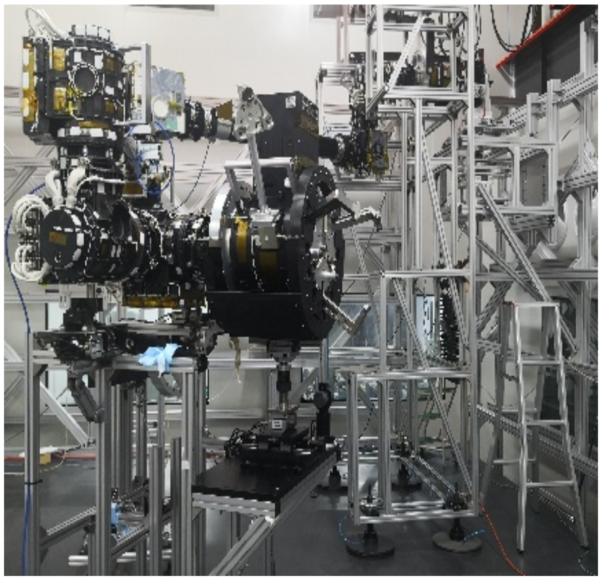
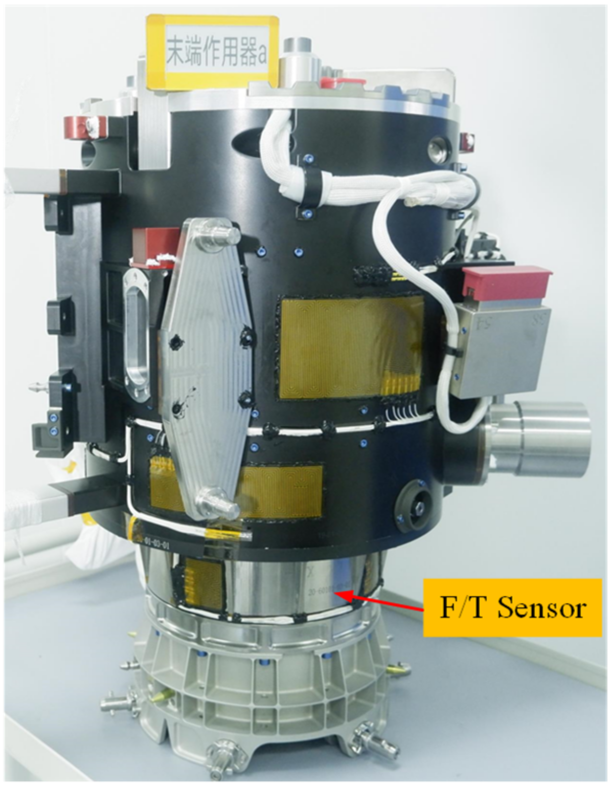
2. Space Manipulator and F/T Sensor

The EMM, shown in Figure 1, is a 7 DOF manipulator. It includes two wrist joints (6 DOF), one elbow joint (1 DOF), two rods, two F/T sensors and two end effectors (EE). The EMM is 5 meters long when it is unfolded. The F/T sensor fixed between the end effector and modular interface, is shown in Figure 2.

3. F/T Sensor Design

3.1. Measuring Principle

The F/T sensor uses resistance strain gauges to detect small deformations [13,14,15,16,17]. Resistance-strain-testing technology is a very mature technology in the field of force/moment/torque sensors. Under the action of an external load, a strain gauge is used to convert the small elastic deformation of the metal into a change in the resistance of the strain gauge, and a Wheatstone bridge is applied to convert the resistance change into a voltage or current signal, thereby realizing the conversion of the difficult-to-measure non-electricity information into an easy-to-measure electricity signal.

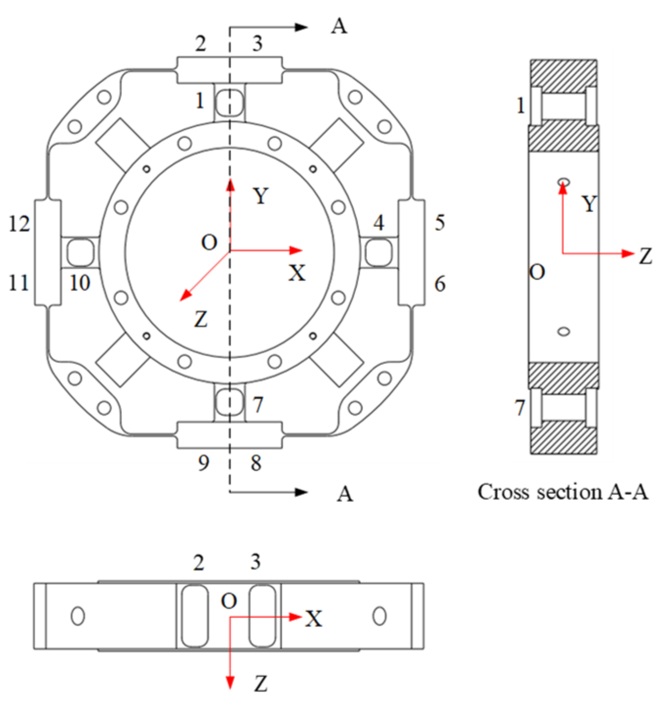
3.2. Sensor Structure Design

Considering the performance of sensors and aerospace products, titanium alloy material Ti-6Al-4V was selected. It is a monolithic elastic element, and the structure is symmetrical. The sensor model is shown in Figure 3.

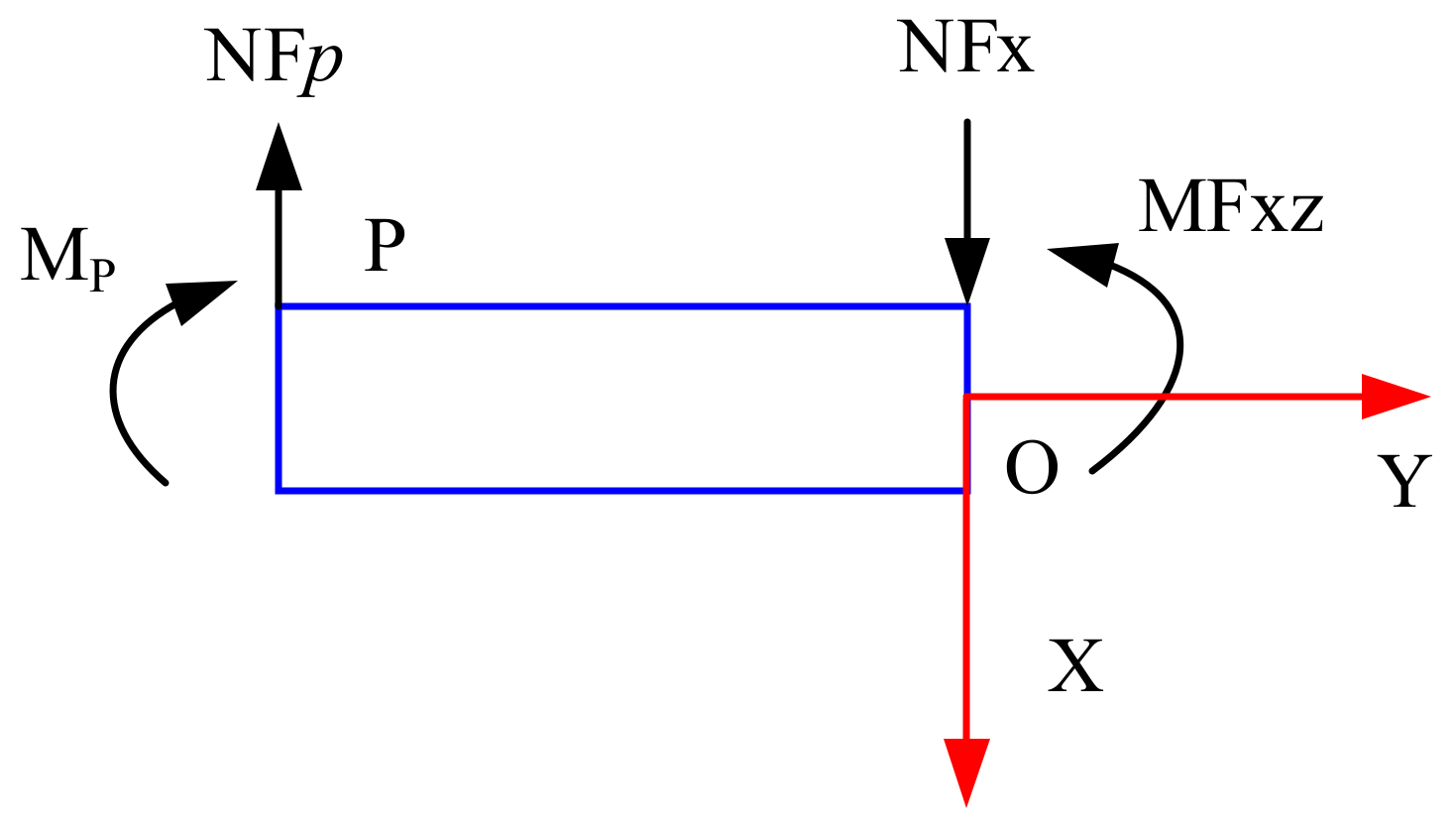
3.3. Strain Analysis Based on Analytical Method

Strain distribution is essential for the design of F/T sensors, for which the analytical method is the common method [18,19,20,21].

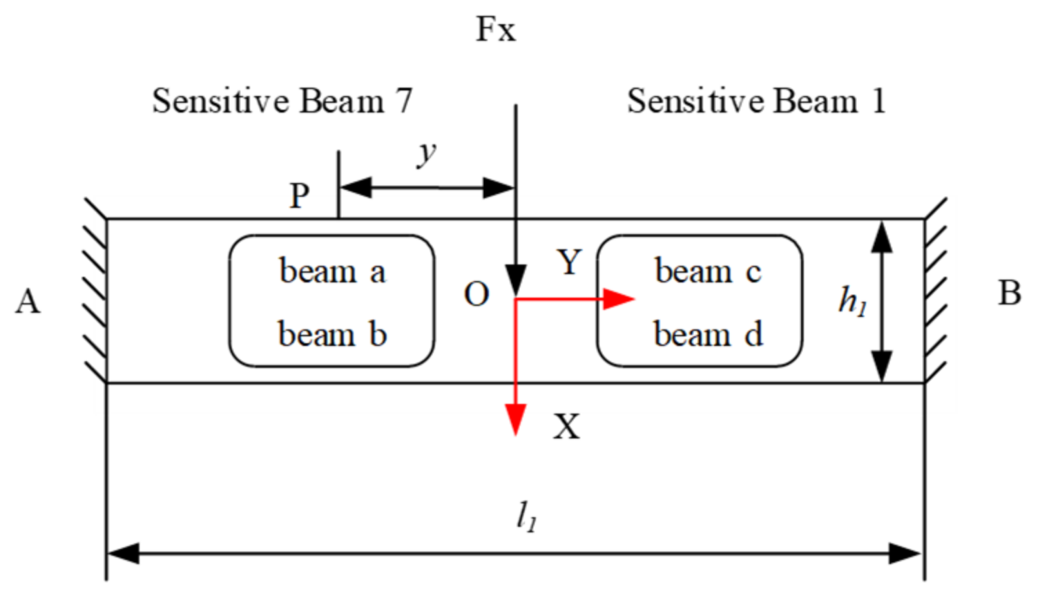
3.3.1. Fx/Fy/Fz Force Analysis

Figure 4 shows the free body diagram of the plate beams for the Fx sensor or the Fy sensor under the force of Fx or Fy. It can be seen that, in Figure 3, sensitive beam 1 and 7 are symmetrical on the vertical axis (X-axis), and sensitive beam 1 and 7 are symmetrical on the horizontal axis (Y-axis), and also sensitive beam 4 and beam 10 are symmetrical on the horizontal/vertical axis. Thus, equations are used for analyzing the strains inferred on the upper and the lower surfaces of beam 1, and these may applied to beam 7, 4 and 10. The equations under the force Fx may be applied to sensitive beam 4 and 10 for the Fy sensor, because sensitive beam 1 and 7, and 4 and 10 are the same in the structure.
According to the theory of mechanics, the loading forces at points A and B can be known. Taking point A as the research object, MA = l1/8 and NFA = Fx/2. Taking the OA segment as the research object for force analysis, the force diagram is shown in Figure 5.
From the force balance relationship at point A, the moment equilibrium condition is M A = 0 [22].
NFx = Fx/2
M A + M F x z N F x l 1 2 = 0
Therefore,
MFxz = Fxl1/8
Take any point P on sensitive beam 6, and the force analysis is shown in Figure 6.
It can be seen from the moment balance at point P, the moment equilibrium condition is M P = 0 [22].
M P + M F x z N F x · y = 0
Therefore,
M P = N F x · y M F x z = F x 2 ( y l 1 4 ) = 0
Therefore, the strain at any point P on sensitive beam 7 is
ε = MP/EIZ
According to Figure 5 and Figure 6, IZ can be obtained from the principle of the superposition method in mechanics
IZ = IZ1IZ2 = 1/6 b1t1(3h12 − 6h1t1 + 4t12)
Substituting Equations (5) and (7) into (6), the strain on any point P on sensitive beam 7 can obtained as
ε P = 3 F x ( y l 1 / 4 ) E b 1 t 1 ( 3 h 1 2 6 h 1 t 1 + 4 t 1 2 )

3.3.2. Mx/My/Mz Moment Analysis

Taking Mx as the object and performing strain analysis, the force analysis under Mx can be seen, as shown in Figure 7. Mx can be equivalent to a pair of force couples. Assuming that the force arm is d, the force acting on sensitive beams 9 and 8, and sensitive beams 2 and 3 is
FZMx = Mx/d
Therefore, similar to the Fx, the strain of Q and R at any point can be obtained as
ε Q = 3 M x ( x l 2 / 4 ) E b 2 t 2 ( 3 h 2 2 6 h 2 t 2 + 4 t 2 2 ) d
ε R = 3 M x ( x l 2 / 4 ) E b 2 t 2 ( 3 h 2 2 6 h 2 t 2 + 4 t 2 2 ) d

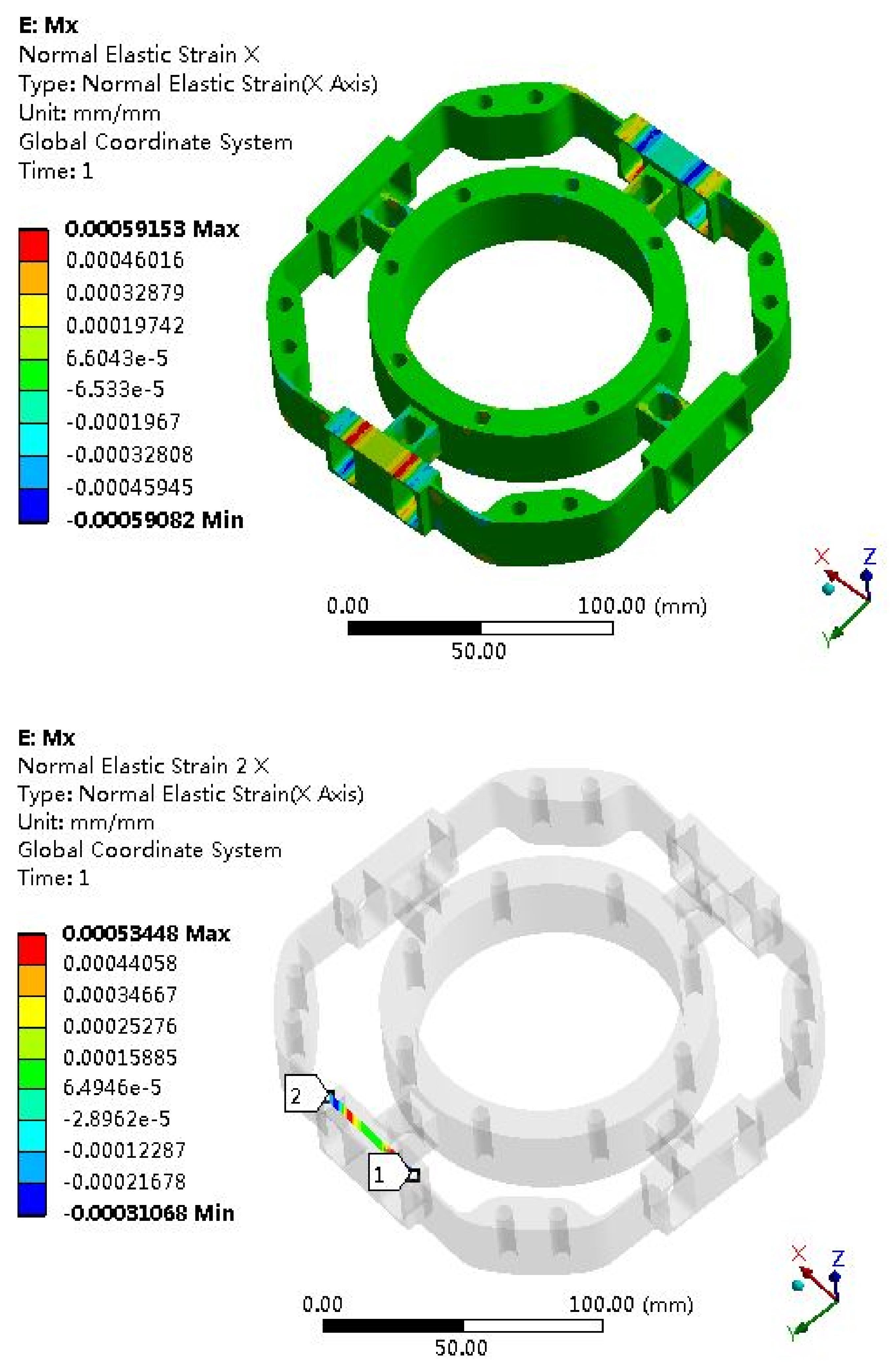
3.4. Strain Analysis by Finite Element Method

Fx Strain Analysis
Compared with the analytical methods, finite element methods have higher solution accuracy and are widely used in engineering applications.
The elastomer of the F/T sensor plays an important role, and the structural optimization of the elastomer usually adopts the finite element method. Due to the symmetry of the elastomer, it can be seen as four cases: Fx (Fy), Fz, Mx (My) and Mz. The strain clouds are shown in Figure 8, Figure 9, Figure 10 and Figure 11.
Fz Strain Analysis
Figure 9. Strain cloud map under Fz = 500 N.
Sensors 22 03603 g009
Mx Strain Analysis
Figure 10. Strain cloud map under Mx = 100 Nm.
Sensors 22 03603 g010
Mz Strain Analysis
Figure 11. Strain cloud map under Mz = 100 Nm.
Sensors 22 03603 g011

3.5. Strain Gauges Selection and Arrangement

We selected a high-precision strain gauge; the model is TK-05-T011Q-350/DP and the manufacturer is Micro-Measurements of Vishay Precision Group. According to the finite element simulation results for the elastomer, the pasting positions of strain gauges can be seen and are shown in Figure 12. Thirty-two strain gauges are pasted on the F/T sensor. Moreover, each four-strain gauge forms a full bridge, so eight full bridges are formed.

3.6. Sensor Electrical System Design

The block diagram of the electrical system for the F/T sensor is shown in Figure 13. It shows the complete AD acquisition of force/torque information, temperature (elastomer and circuit board) and analog reference voltage, DA setting output and RS422 serial communication. It includes the following functional modules:
(1)
Power module. After filtering the digital 7.5 V power provided by the controller circuit, the voltage is converted into digital 5 V; then, the digital 5 V voltage is converted into digital 2.5V and analog 5V; finally, the analog 5V is converted into analog 2.5 V;
(2)
The communication interface module. Through the RS422 serial communication protocol, this realizes the data interaction with the end effector controller;
(3)
AD interface module. This realizes eight channels of force/torque, five channels of temperature and three channels of analog reference voltage information collection from the elastomer. The original force/torque signal is amplified by the triple-instrument amplifier circuit, and the filtered signal input goes to the analog-to-digital conversion module to achieve analog-to-digital conversion;
(4)
DA interface module. This realizes the compensation voltage and feeds it back to the output terminal of the electric bridge to compensate the zero drift of the F/T sensor.

4. Space Environment Adaptability Design of F/T Sensor

4.1. Mechanical Vibration Design

As part of the EMM, the F/T sensor needs to carry a rocket into space with the EM. Therefore, the F/T sensor will be subject to mechanical vibration as it enters space. Therefore, mechanical vibration design must be considered. Figure 14 shows the three-dimensional model and coordinate system definition of the EE alone in the vibration test.
The mechanical analysis model construction was founded on the following principles: (1) in the key force transmission path, the mesh is dense; (2) the non-critical parts are simplified based on the principle of equivalent energy and stiffness.
According to the above principles, shell elements and solid elements are used as structural elements when modeling. The finite element model and restraint positions of the EE are shown in Figure 15.

4.2. Thermal Control Design

According to the orbital characteristics of the CSS, the working mode of the EMM, the position of the heat dissipation surface, the performance of the thermal control coating and the temperature requirements of each component, a combination of passive thermal control and active thermal control can use to achieve thermal protection of the F/T sensor.

4.2.1. Passive Thermal Control

The outer surface of the F/T sensor shell is covered by 20-unit multi-layer insulation components and the mask uses an external flame-retardant cloth. The housing of the F/T sensor and the bottom flange of the EE are heat conductors.

4.2.2. Active Thermal Control

The F/T sensor shell and the EE are equipped with a heating zone. The main loop of the heating circuit is controlled by a temperature relay; the backup loop is controlled by temperature relay and a thermistor sensor. All thermistor sensors are arranged on the EE. The layout of the heating element of the F/T sensor is shown in Figure 2.

4.3. Anti-Radiation Design

The F/T sensor mainly realizes the acquisition of force/torque information and temperature information, which integrates semiconductor electronic components, digital logic circuits, etc.; therefore, radiation protection design is required.

4.3.1. Protection Design of Total Ionization Dose Effect

The F/T sensor has one data-acquisition circuit board with a thickness of 2.0 mm, inside the sensor, protected by a thick shell, and the environment is relatively good. The thickness of the F/T sensor housing is 4 mm titanium alloy. From the above radiation shielding analysis, the internal radiation dose D0 of the electronic product under the shielding can be determined. According to the total dose resistance data (D1) of the components and materials in the sensor, and the internal dose value (D0) of the electronic product, the satisfaction of the total dose effect requirement is obtained. The criteria are as follows: (1) if D1/D0 ≥ RDM, it satisfied the requirement of the total anti-ionization dose; (2) if D1/D0 < RDM, the total anti-ionization dose requirement is not satisfied, and the protection design must be applied.

4.3.2. Single-Event Effect Protection

(1)
Single-event upset (SEU) protection
  • The main measures are as follows:
    • Select FPGA with FLASH structure;
    • Optimize circuit structure.
(2)
Single-event latch effects (SEL) protection
  • A resistance-capacitance network is designed at the power input of the circuit board, a series of current-limiting resistors, and a decoupling tantalum capacitor are used to prevent the power supply from triggering lock due to overvoltage.
  • In terms of component selection, anti-locking chips, such as CPU, RAM, PROM, etc., are preferred for important and key components.
  • We designed a power supply circuit with the function of preventing SEL to realize the protection of the chip.
  • Using multi-layer printed boards, the power supply and ground each occupy one layer, which improves the power supply loop.
  • We placed a filter capacitor near the power terminal of the CMOS device. The external signal input terminal does not connect to the CMOS device directly. The external signal CMOS output adopts diode isolation. The input floating pins of all CMOS devices are grounded or connected to the power supply.

5. Manufacture of F/T Sensor

The manufacturing process of the F/T sensor affects the performance of the sensor directly. It includes the following steps: (1) processing of elastomer, (2) strain gauge paste and wire bonding, (3) strain gauge numbers and Wheatstone bridges building, (4) strain gauge resistance measurement, (5) Wheatstone bridges trimming, (6) electrical system processing, (7) debugging and preventions, (8) electrical systems and elastomers strain gauge electromechanical integration, (9) debugging and (10) sensor assembly. The main manufacturing process of the F/T sensor is shown in Figure 16.

6. Calibration of F/T Sensor

The calibration of the F/T sensor has a significant effect on the measurement accuracy. It is key to carry out the calibration experiment and calculate the calibration matrix, which reflects the characteristics of the F/T sensor. Suppose the F/T sensor is a linear system, then the output voltage of each Wheatstone bridge and the corresponding force/torque applied to the origin of the sensor coordinate system has a linear relationship, and the expression is as follows:
U = AF + B
In Equation (12), URn × 1 is the Wheatstone bridge output vector of the F/T sensor; ARn × m is the F/T sensor calibration matrix; FRm × 1 is the generalized force vector; BRn × 1 is the intercept of the sensor; m is the dimensional of measuring the generalized force and n is the number of Wheatstone bridges.

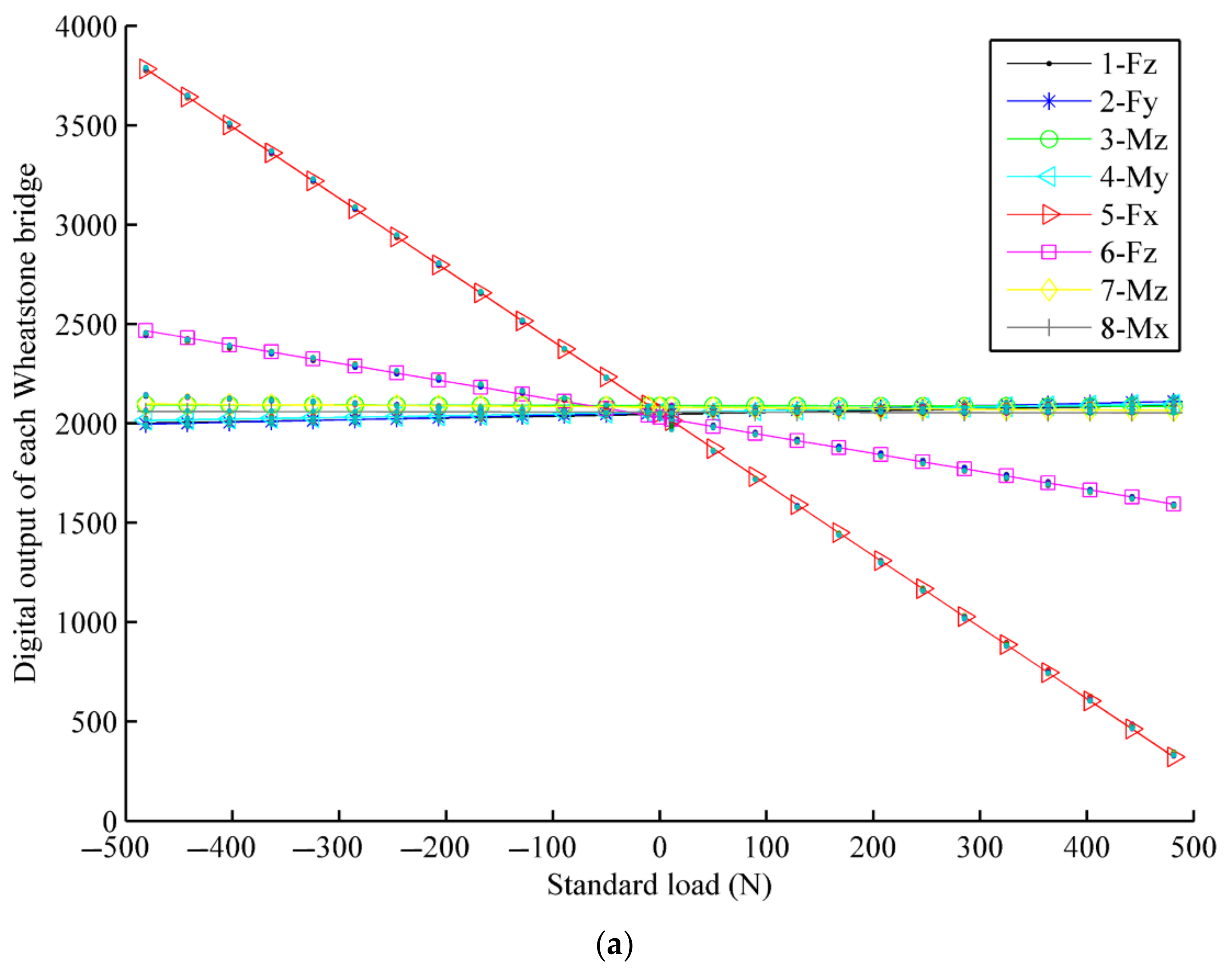
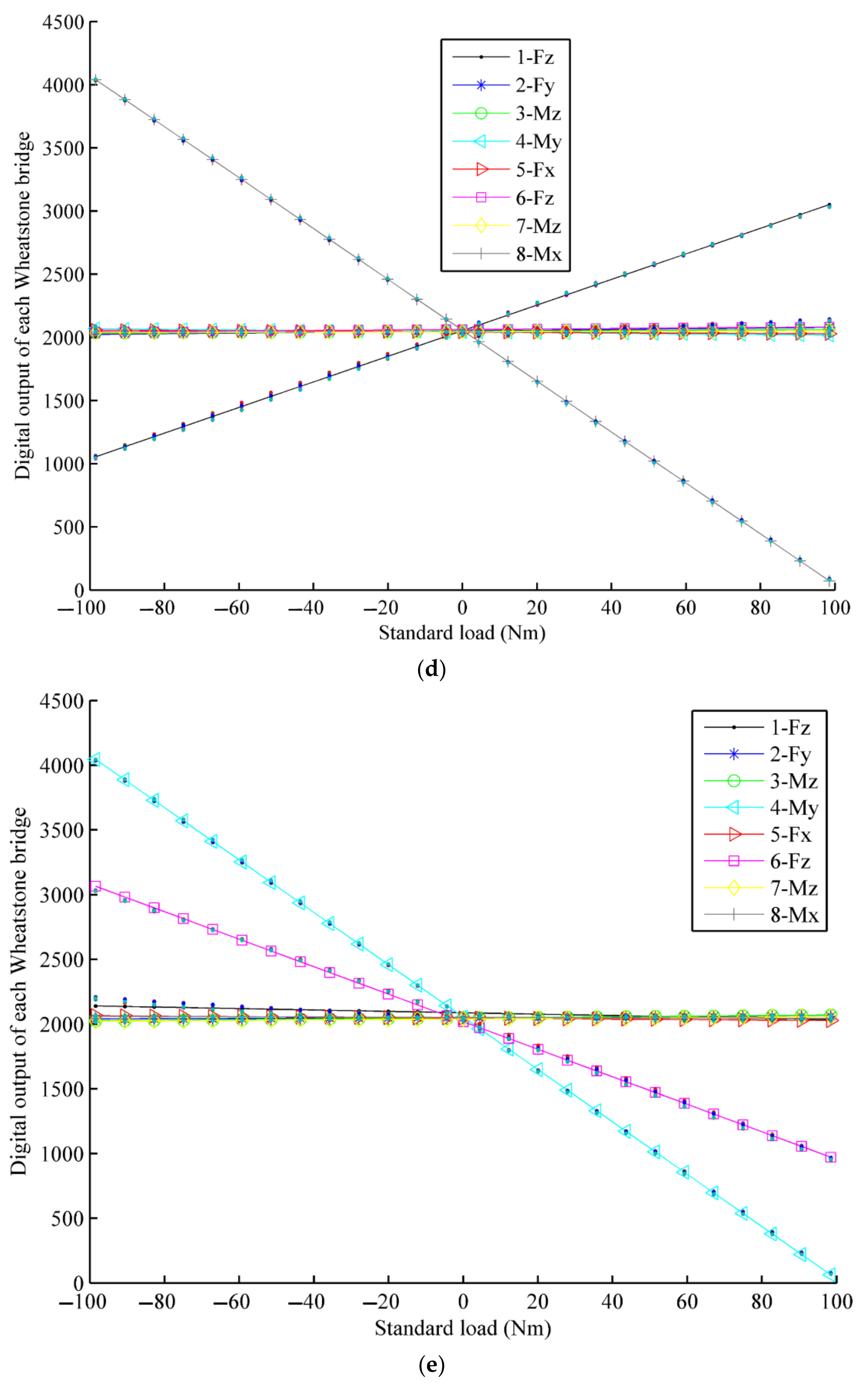
6.1. Calibration F/T Sensor by Experiment

The sensor is calibrated by a pulley weight system, which is shown in Figure 17.
The calibration experiment results by least squares method are shown in Figure 18.
By processing the experimental data of the F/T sensor, the performance of the F/T sensor developed can be seen, as shown in Table 1. The following conclusions can be obtained from Table 1: the linearity of the sensor is less than 3%, the maximum linearity is 2.60% in the Fz, and the minimum linearity is 0.56% in the Fy; the maximum hysteresis characteristic of the sensor is 1.4% of the Fz, and the minimum hysteresis characteristic of the sensor is 0.51% of the My; the stability of the sensor is good, and the maximum stability error is 0.39% of the Fz; the maximum repeatability error is 1.72% in the My, the minimum repeatability error is 0.49% of the Fx; the accuracy of the sensor is high, the maximum accuracy is 1.18% in the Fz, and the minimum accuracy is 0.49 % in the Mx.
It can be seen from Table 1 that the sensor has good linearity, hysteresis, stability, repeatability and the accuracy. In addition, the Fz direction has the worst linearity, hysteresis and accuracy.
The sensor coupling errors obtained are shown in Table 2. It can be seen from Table 2 that the maximum coupling error in the Fx is −1.81%; the maximum coupling error in the Fy is −1.15%; the maximum coupling error in the Fz is 0.54%; the maximum coupling error in the Mx is −0.78%; the maximum coupling error in the My is 0.59% and the maximum coupling error in the Mz is 1.24%.

6.2. Error Analysis of Strain Simulation and Experimental Test

According to the F/T sensor experimental test, the test measurement strain can be obtained; then, the error between the simulation and the measurement will be calculated. The strain simulation results are shown in Figure 8, Figure 9, Figure 10 and Figure 11. Strain measurement and error are shown in Table 3. It can see from Table 3 that the absolute errors between the measurement strains and the simulation strains are less than 10%, indicating that the simulation results are accurate and credible.

7. Sensor Space Environmental Adaptability Test

7.1. Mechanical Vibration Test

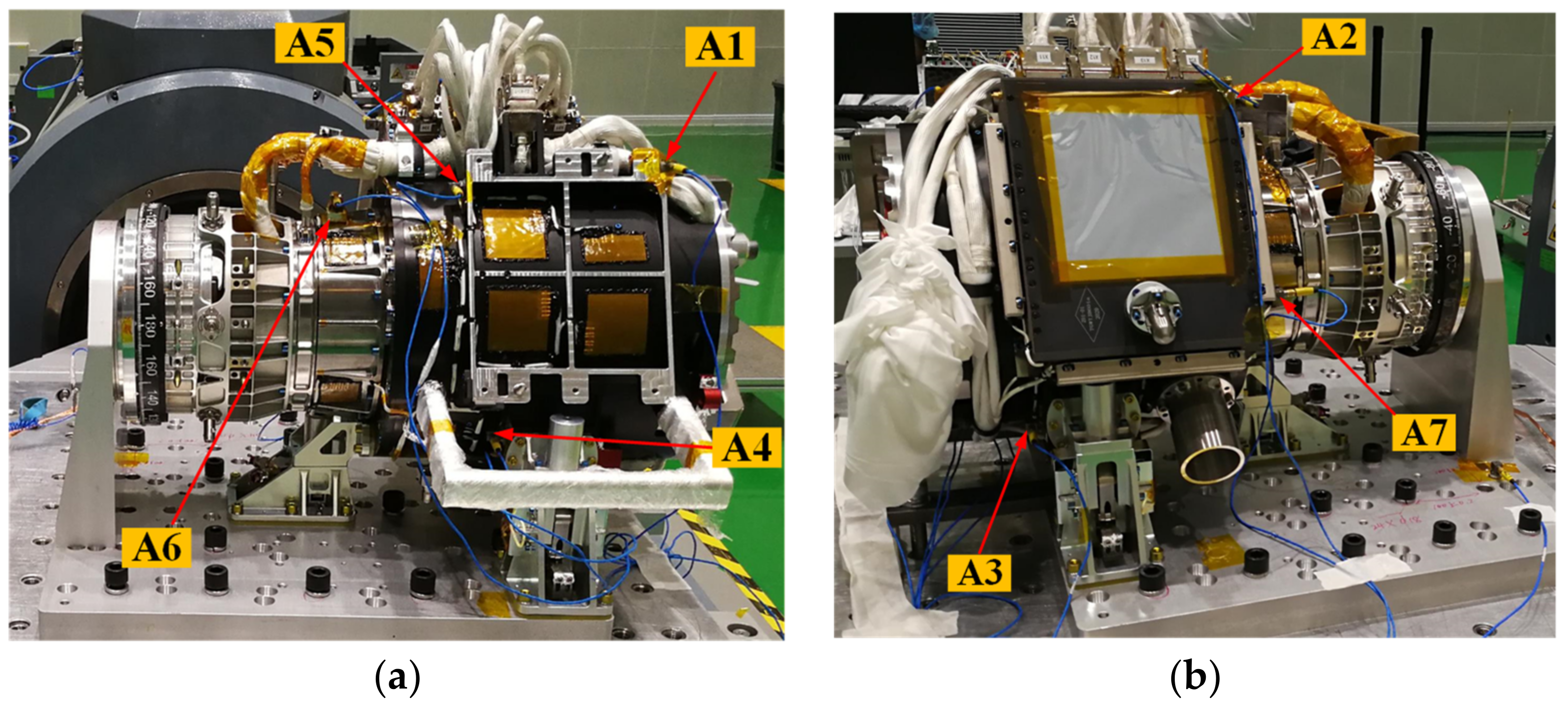
7.1.1. Measuring Acceleration Sensor Layout

The EE and F/T sensor are installed with seven acceleration points in the vibration test, which are all three-axis acceleration sensors, and the direction is consistent with the global coordinate system. The specific locations of the measuring points are shown in Figure 19.

7.1.2. Sinusoidal Vibration Test Conditions

The sinusoidal vibration conditions are shown in Table 4.

7.1.3. Random Vibration Test Conditions

The conditions of random vibration are shown in Table 5.

7.1.4. Vibration Test Results

The sinusoidal vibration test data are shown in Table 6. It can see that the maximum response of sinusoidal vibration acceleration is 13.00 g, magnified 3.33-times, which occurred at measuring point A2 in the Y direction.
The random vibration test data are shown in Table 7. It can be seen that the maximum response of random vibration is 20.05 grms, and the magnification is 3.08-times, which occurs at the measuring point A1 in the X direction.

7.2. Thermal Vacuum Environment Test

The thermal vacuum test is a must-do test for aerospace products. It is used to test the working performance of the product in a vacuum environment and under high and low temperature changes.

7.2.1. Thermal Vacuum Test Conditions

The thermal vacuum test conditions are as follows:
(a)
Environmental pressure: no more than 1.3 × 10⁻³ Pa;
(b)
Test temperature: The temperature range is −35 °C~+55 °C. The temperature of the heat sink under low-temperature conditions is lower than −70 °C, and the temperature of the heat sink under high-temperature conditions is higher than +20 °C;
(c)
Average temperature change rate: not less than 1 °C/min; temperature change rate should be at least >0.5 °C/min (according to equipment capability);
(d)
Number of cycles: 3.5 cycles for main part and 2 cycles for backup;
(e)
Reference point test temperature tolerance: low temperature is 0 °C~−4 °C and high temperature is +4 °C~0 °C.

7.2.2. Load Simulation Device of Thermal Vacuum Test

The load simulation device for the thermal vacuum test is shown in Figure 20. The thermal vacuum test of the EE and F/T sensor needs to test the two products, in terms of the axial force and the lateral force of the EE. The axial force and lateral force of the device can be loaded with a load of 100 N, applied by weights and fixed pulleys, independently. Under the action of the F/T sensor, the lateral force and axial force of the end effector can be tested during the whole movement. The device can realize the thermal vacuum test of the EE and the F/T sensor.

7.2.3. Thermal Vacuum Test Results

The acceptance-level thermal vacuum test of the F/T sensor and EE has 5.5 cycles. The Thermal vacuum test results of the F/T sensor are shown in Figure 21. Across all 5.5 cycles, the minimum temperature of the sensor is −37.37 °C, and the maximum temperature is 57.1 °C.

7.2.4. Force/Torque Information during Grasping and Releasing Progress of EE

Force/torque information during grasping and releasing progresses the target adapter of EE, measured by the F/T sensor, as shown in Figure 22. The test results show that the thermal vacuum test device can effectively complete the thermal vacuum test of the F/T sensor and the EE. The F/T sensor meets the thermal vacuum environment requirements of EMM on-orbit application.

8. Conclusions

This paper focused on the development of the F/T sensor for the EMM of the CSS. The F/T sensor is made of a titanium alloy material, and the strain analysis is based on the analytical method and finite element method. Furthermore, the electrical system mainly accomplished the information acquisition of force/torque, AD, temperature, analog voltage, DA setting and RS422 serial communication. In view of the adaptability of the space environment, the F/T sensor was designed with mechanical vibration, thermal control and anti-radiation properties. Subsequently, the manufacturing process of the sensor is explained in detail. Then, a calibration test is carried out, and the test results showed that the developed F/T sensor has good linearity, hysteresis, stability, repeatability, accuracy and coupling error. Finally, a mechanical vibration test and a thermal vacuum test were carried out. The test results showed that the developed sensor meets the requirements and has the ability for on-orbit application.

Funding

This work was supported by the National Natural Science Foundation of China (51805107) and China Postdoctoral Science Foundation (2018M641818, 2021T140159).

Institutional Review Board Statement

Not applicable.

Informed Consent Statement

Not applicable.

Data Availability Statement

Not applicable.

Acknowledgments

Thanks go to Zongwu Xie, Yuanfei Zhang and Kui Sun of the Harbin Institute of Technology, Qingwen Wu, Richa Hu, Yang Zhao and Shuai He from the Changchun Institute of Optics, Fine Mechanics and Physics (CIOMP) and the Chinese Academy of Sciences for their help in the space environment adaptability test.

Conflicts of Interest

The authors declare no conflict of interest.

References

  1. Liu, H. An Overview of the Space Robotics Progress in China. In Proceedings of the 12th International Symposium on Artificial Intelligence, Robotics and Automation in Space, Montreal, QC, Canada, 17–19 July 2014; Volume 14, pp. 15–22. [Google Scholar]
  2. Gibbs, G.; Sachdev, S. Canada and the international space station program: Overview and status. Acta Astronaut. 2002, 51, 591–600. [Google Scholar] [CrossRef]
  3. Cruijssen, H.J.; Ellenbroek, M.; Henderson, M.; Petersen, H.; Verzijden, P.; Visser, M. The European Robotic Arm: A High-Performance Mechanism Finally on its Way to Space. In Proceedings of the 42nd Aerospace Mechanism Symposium, Baltimore, MD, USA, 14–16 May 2014; pp. 319–334. [Google Scholar]
  4. Boumans, R.; Heemskerk, C. The European robotic arm for the international space station. Robot. Auton. Syst. 1998, 23, 17–27. [Google Scholar] [CrossRef]
  5. Kim, J.H. Multi-axis force-torque sensors for measuring zero-moment point in humanoid robots: A review. IEEE Sens. J. 2019, 20, 1126–1141. [Google Scholar] [CrossRef]
  6. Xiong, L.; Guo, Y.; Jiang, G.; Zhou, X.; Jiang, L.; Liu, H. Six-dimensional force/torque sensor based on fiber Bragg gratings with low coupling. IEEE Trans. Ind. Electron. 2020, 68, 4079–4089. [Google Scholar] [CrossRef]
  7. Li, K.; Pan, B.; Zhang, F.; Gao, W.; Fu, Y.; Wang, S. A novel 4-DOF surgical instrument with modular joints and 6-Axis Force sensing capability. Int. J. Med. Rob. Comput. Assist. Surg. 2017, 13, e1751. [Google Scholar] [CrossRef] [PubMed]
  8. Tan, Y.; Wang, X.; Ren, L. Design and experiment of a cardan-type self-decoupled and self-powered bending moment and torque sensor. IEEE Trans. Ind. Electron. 2020, 68, 5366–5375. [Google Scholar] [CrossRef]
  9. Hosseinabadi, A.H.H.; Black, D.G.; Salcudean, S.E. Ultra low-noise FPGA-based 6-axis optical force-torque sensor: Hardware and software. IEEE Trans. Ind. Electron. 2021, 68, 10207–10217. [Google Scholar] [CrossRef]
  10. He, Z.; Liu, T. Design of a three-dimensional capacitor-based six-axis force sensor for human-robot interaction. Sens. Actuators A 2021, 331, 112939. [Google Scholar] [CrossRef]
  11. Eng, S.; Al-Mai, O.; Ahmadi, M. A 6 DoF, wearable, compliant shoe sensor for total ground reaction measurement. IEEE Trans. Instrum. Meas. 2018, 67, 2714–2722. [Google Scholar] [CrossRef]
  12. Li, Y.J.; Yang, C.; Wang, G.C.; Zhang, H.; Cui, H.Y.; Zhang, Y.L. Research on the parallel load sharing principle of a novel self-decoupled piezoelectric six-dimensional force sensor. ISA Trans. 2017, 70, 447–457. [Google Scholar] [CrossRef] [PubMed]
  13. Wang, Y.J.; Hsu, C.W.; Sue, C.Y. Design and calibration of a dual-frame force and torque sensor. IEEE Sens. J. 2020, 20, 12134–12145. [Google Scholar] [CrossRef]
  14. Payo, I.; Adánez, J.M.; Rosa, D.R.; Fernandez, R.; Vazquez, A.S. Six-axis column-type force and moment sensor for robotic applications. IEEE Sens. J. 2018, 18, 6996–7004. [Google Scholar] [CrossRef]
  15. Kang, M.K.; Lee, S.; Kim, J.H. Shape optimization of a mechanically decoupled six-axis force/torque sensor. Sens. Actuators A 2014, 209, 41–51. [Google Scholar] [CrossRef]
  16. Dwarakanath, T.A.; Bhutani, G. Beam type hexapod structure based six-component force-torque sensor. Mechatronics 2011, 21, 1279–1287. [Google Scholar] [CrossRef]
  17. Wang, Y.; Zuo, G.; Chen, X.; Liu, L. Strain analysis of six-axis force/torque sensors based on analytical method. IEEE Sens. J. 2017, 17, 4394–4404. [Google Scholar] [CrossRef]
  18. Gobbi, M.; Previati, G.; Guarneri, P.; Mastinu, G. A new six-axis load cell. Part II: Error analysis, construction and experimental assessment of performances. Exp. Mech. 2011, 51, 389–399. [Google Scholar] [CrossRef]
  19. Wu, B.; Cai, P. Decoupling analysis of a sliding structure six-axis force/torque sensor. Meas. Sci. Rev. 2013, 13, 187–193. [Google Scholar] [CrossRef] [Green Version]
  20. Mastinu, G.; Gobbi, M.; Previati, G. A new six-axis load cell. Part I: Design. Exp. Mech. 2011, 51, 373–388. [Google Scholar] [CrossRef] [Green Version]
  21. Sun, Y.; Liu, Y.; Jin, M.; Liu, H. Design and Optimization of a Novel Six-Axis Force/Torque Sensor with Good Isotropy and High Sensitivity. In Proceedings of the 2013 IEEE International Conference on Robotics and Biomimetics (ROBIO), Shenzhen, China, 12–14 December 2013; pp. 631–638. [Google Scholar]
  22. Park, J.J.; Kim, G.S. Development of the 6-axis force/moment sensor for an intelligent robot’s gripper. Sens. Actuators A 2005, 118, 127–134. [Google Scholar] [CrossRef]
Figure 1. Space manipulator.
Sensors 22 03603 g001
Figure 2. F/T sensor on EE.
Sensors 22 03603 g002
Figure 3. Sensor model.
Sensors 22 03603 g003
Figure 4. Free body diagram of the sensitive beams for Fx.
Sensors 22 03603 g004
Figure 5. Free body diagram of the plate beams.
Sensors 22 03603 g005
Figure 6. Free body diagram of the plate beams for Fz.
Sensors 22 03603 g006
Figure 7. Free body diagram of the plate beams for Fz. (a) Free body diagram of the sensitive beam 8 and beam 9; (b) Free body diagram of the sensitive beam 2 and beam 3.
Sensors 22 03603 g007
Figure 8. Strain cloud map under Fx = 500 N.
Sensors 22 03603 g008
Figure 12. Position distribution of strain gauges.
Sensors 22 03603 g012
Figure 13. Block diagram of the electrical system in the F/T sensor.
Sensors 22 03603 g013
Figure 14. The 3D model and coordinate system definition.
Sensors 22 03603 g014
Figure 15. The finite element model of the EE and F/T sensor.
Sensors 22 03603 g015
Figure 16. The main manufacturing process of the F/T sensor (ai).
Sensors 22 03603 g016
Figure 17. Calibration testbed.
Sensors 22 03603 g017
Figure 18. The calibration of F/T sensor. (a) The calibration of force Fx; (b) The calibration of force Fy; (c) The calibration of force Fz; (d) The calibration of Mx; (e) The calibration of My; (f) The calibration of Mz.
Sensors 22 03603 g018aSensors 22 03603 g018bSensors 22 03603 g018cSensors 22 03603 g018d
Figure 19. Measuring acceleration sensor position. (a) Position of measuring acceleration sensor A1, A4, A5, A6; (b) Position of measuring acceleration sensor A2, A3, A7.
Sensors 22 03603 g019
Figure 20. Load simulation device of thermal vacuum test of EE and F/T sensor.
Sensors 22 03603 g020
Figure 21. Temperature curve of sensor body.
Sensors 22 03603 g021
Figure 22. Six-dimensional force/torque information during the operation of the end effector grasping and releasing the target adapter.
Sensors 22 03603 g022
Table 1. The static performance of F/T sensor.
IndexFxFyFzMxMyMz
Range(N/Nm)±500±500±500±100±100±100
Linearity1.25%0.56%2.60%0.92%0.91%1.63%
Hysteresis0.93%0.73%1.42%0.63%0.59%1.07%
Stability0.10%0.10%0.39%0.10%0.10%0.10%
Repeatability0.49%1.07%0.82%1.41%1.72%1.17%
Accuracy0.75%0.53%1.18%0.49%0.53%0.84%
Table 2. The coupling error of F/T sensor.
Coupling Error (%)
FxFyFzMxMyMz
Fx-−0.33−0.060.070.350.23
Fy−0.27-−0.32−0.02−0.331.24
Fz0.500.54-−0.78−0.260.05
Mx0.020.36−0.36-0.59−0.20
My−0.320.34−0.14−0.08-0.06
Mz−1.81−1.150.540.430.48-
Table 3. Error between strain simulation and experimental test.
Bridge 1-FzBridge 2-FyBridge 3-MzBridge 4-MyBridge 5-FxBridge 6-FzBridge 7-MzBridge 8-Mx
Simulation384.8 μ1014.2 μ1376.5 μ1690.3 μ1014.2 μ384.8 μ1376.5 μ1690.3 μ
Test365.4 μ948.0 μ1269.9 μ1743.8 μ924.0 μ394.4 μ1252.8 μ1736.7 μ
Error−5.04%−6.53%−7.74%3.17%−8.89%2.49%−8.99%2.75%
Table 4. Sinusoidal vibration test conditions.
Parameter NameReference
Frequency Range (Hz)
5~1010~1717~2525~4545~7575~100
Amplitude 0-pX, Y, Z directionAcceptance level8.5 mm3.4 g4.0 g9.5 g3.0 g3.9 g
Load scan rateAcceptance level4 oct/min
Loading directionThree axis
Table 5. Random vibration test conditions.
Parameter NameReference
Frequency Range (Hz)Total Root Mean Square(grms)
10–250 Hz250–600 Hz600–2000 Hz
Power Spectral DensityAcceptance level (X,Y,Z)6 dB/Oct0.06 g2/Hz−9 dB/Oct6.5 grms
Duration of each directionAcceptance level60 s
Loading directionThree axis
Table 6. Sinusoidal vibration response data.
DirectionMeasuring PointAcceptance Grade SineDirectionMeasuring PointAcceptance Grade SineDirectionMeasuring PointAcceptance Grade Sine
Frequency (Hz)Acceleration (g)Frequency (Hz)Acceleration (g)Frequency (Hz)Acceleration (g)
XA144.9810.39YA199.7212.34ZA134.5110.72
A244.9810.25A299.7213.00A234.6610.31
A344.989.76A343.759.76A334.7111.19
A444.789.74A444.989.80A434.4610.20
A545.1110.26A599.7211.80A534.3110.06
A644.9810.15A699.7210.93A634.619.94
A744.989.91A744.7210.27A734.7110.15
Table 7. Random vibration response data.
DirectionMeasuring PointDirectionAcceptance Level RandomDirectionMeasuring PointDirectionAcceptance Level RandomDirectionMeasuring PointDirectionAcceptance Level Random
Root Mean Square Acceleration (grms)Root Mean Square Acceleration (grms)Root Mean Square Acceleration (grms)
XA1X20.05YA1X14.63ZA1X16.71
Y6.49Y8.12 Y9.04
Z9.69Z12.10 Z11.80
A2X11.15A2X5.42A2X8.49
Y6.39Y7.30 Y7.85
Z4.92Z5.31 Z11.04
A3X8.81A3X7.48A3X9.13
Y3.81Y8.24 Y6.41
Z7.20Z7.12 Z8.40
A4X9.40A4X7.31A4X8.07
Y4.34Y7.93 Y5.53
Z6.58Z5.53 Z7.86
A5X9.37A5X4.79A5X7.31
Y4.29Y5.25 Y5.05
Z6.22Z5.51 Z10.05
A6X8.52A6X4.32A6X7.22
Y6.38Y8.87 Y9.11
Z3.85Z5.74 Z11.98
A7X7.31A7X3.95A7X5.57
Y4.97Y8.24 Y7.34
Z5.25Z5.76 Z12.60
Publisher’s Note: MDPI stays neutral with regard to jurisdictional claims in published maps and institutional affiliations.

