1. Introduction
A person with a disability is an individual who has one or more physical or mental deficiencies that prevent their full and effective participation in equal conditions when interacting with different social environments. In recent years, the development of HMI for people with motor disabilities has been oriented towards the use of systems based on Electromyography (EMG). In [
1], a review of the state of the art in EMG monitoring is presented in terms of applications in rehabilitation and minimally invasive acquisition devices; among the advantages that it highlights are in the fields of physiotherapy and telemedicine. In [
2], through three EMG channels, they control the position of a robot with two degrees of freedom; the processing is done as a function of time through the amplitude of the signal when movements are made with the elbow and the shoulder joint. Four channels of surface electromyography acquisition are proposed in [
3], where pairs of electrodes are placed according to the position and orientation of the target muscles. Selecting materials with excellent properties for devices on the skin, the fabricated electrodes achieve low skin electrode impedance and record sEMG signals with a high signal-to-noise ratio. In [
4], a review on signal acquisition and pattern recognition through Machine Learning is presented. In [
5], a myoelectric pattern recognition-driven hand exoskeleton was designed for stroke rehabilitation. It detects and recognizes the intention of movement based on EMG signals, and then the exoskeleton helps the user to perform six types of hand movements in a real way. One of the main challenges in the design of interfaces based on sEMG is the obtention of a signal function or model that allows for the reliable control of a care system. Due to the non-stationary signal behavior, three methods are generally used for sEMG analysis to extract information, which are in the time [
6,
7], frequency, and time–frequency domain [
8]. There are some practical factors, such as the change in arm position, that prevent robust myoelectric control. In [
9], an experiment with 14 subjects is carried out to accurately characterize factors that alter the EMG recording. Using regression algorithms, they obtain real-time feedback on changes in the position of the arm and displacement of the electrodes. Pattern recognition has been studied further to develop control algorithms for electric hand prostheses [
10,
11]. These works have shown excellent accuracy when classifying different types of hand movement (>95% for 10 classes), [
12,
13,
14]. Most of the pattern recognition approaches have the limitation that only one of the functions of the prosthetic hand can be controlled, due to its sequential and binary control. Such control strategies make it impossible to perform natural movements of the hand that consist of the simultaneous activation of different degrees of freedom. Some studies have introduced new pattern recognition schemes that classify combined movements [
15,
16,
17,
18,
19]. The disadvantage of the new approach is the total number of classes, as it increases drastically when new classes are considered. Recently, regression-based approaches have been on the rise, as they provide control information that allows for multi-degree-of-freedom control. In this work, a regression algorithm using neural networks is proposed to obtain a model through multiclass categorization that allows for the control of a robotic system with three degrees of freedom of the anthropomorphic type. The analysis of a single channel of sEMG that classifies signals with different times of muscle contraction is implemented, with the objective that the robot moves accurately according to predetermined positions in a state machine and demonstrates the correct operation of an HMI by reducing the learning curve. In [
20], a study of multichannel electromyography signals is carried out, which is one of the methods used in the recognition of human movement patterns. An exoskeleton robot is controlled and EMG signals are measured during dynamic or isometric muscle contractions. As a result, they developed a pattern recognition model of dynamic and isometric muscle contractions using the Short Time Fourier Transform (STFT).
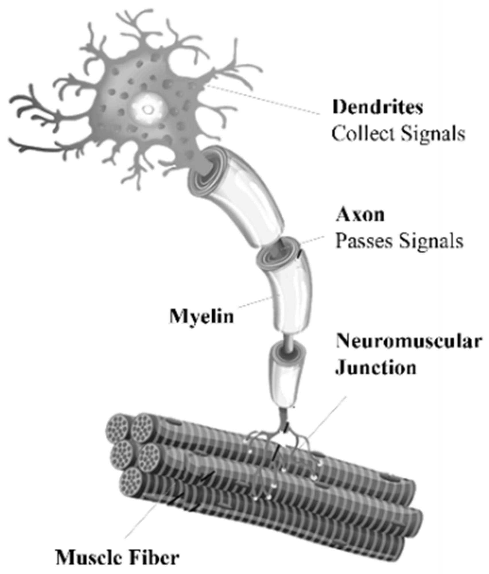
Section 2 presents the fundamentals of the EMG signal.
Section 3 presents the design of the HMI from the acquisition of the EMG signal and its analog and digital processing. The multiclass classification model obtained using neural networks is described. The different classes to be detected, the training algorithm and the operation of a state machine that determines the position of the robot according to the result obtained from the model are shown. The classification to reach the desired position is explained, obtaining the dynamics and inverse kinematics of an anthropomorphic robot with three degrees of freedom. A PD+ control is implemented to apply the necessary torque to each joint of the robot and to validate the operation of the HMI. It designs a graphical user interface in LabVIEW software by interacting a virtual robot and the EMG signal.
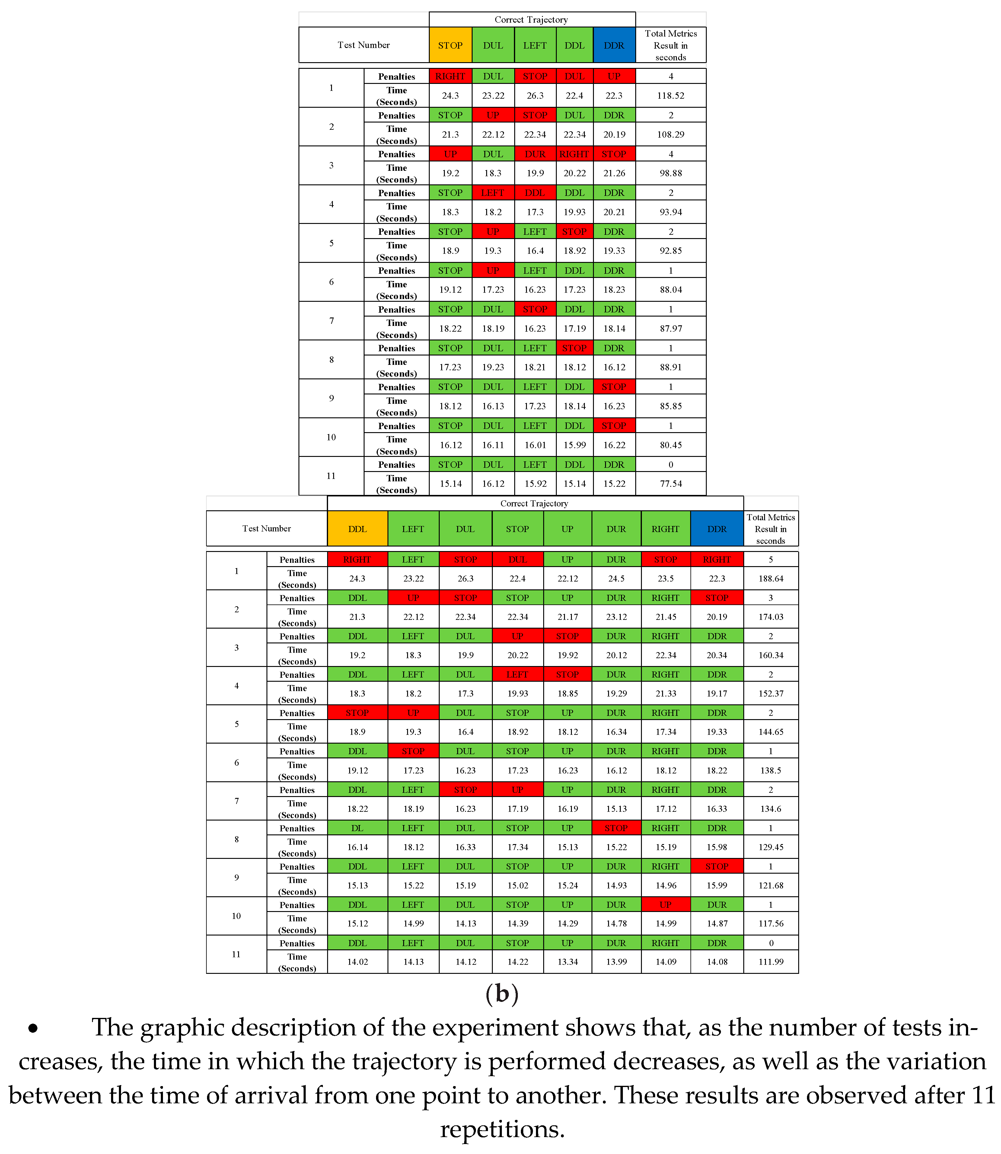
Section 4 describes the results obtained with the classifier, the experimental tests and the response time for each test.
3. Materials and Methods
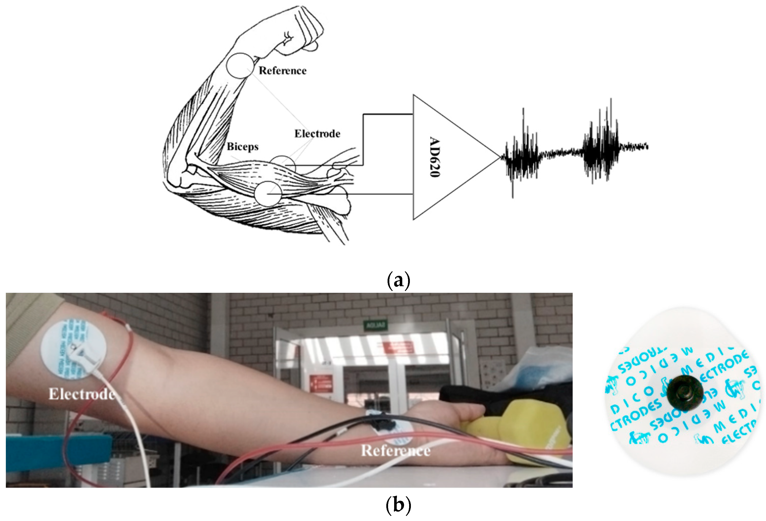
The amplifier used is the IC AD620 due to its characteristic of a common rejection ratio of 100 dB and the gain adjustment with an external resistor. A circuit with a basal corrector and a Common Mode Rejection (CMRR) configuration connected to the junction of the forearm and hand is implemented as a circuit reference. According to the amplitude and frequency characteristics of the EMG signal, the analog processing stage is designed, which includes amplification, isolation and filtering.
- A.
Amplification with basal corrector
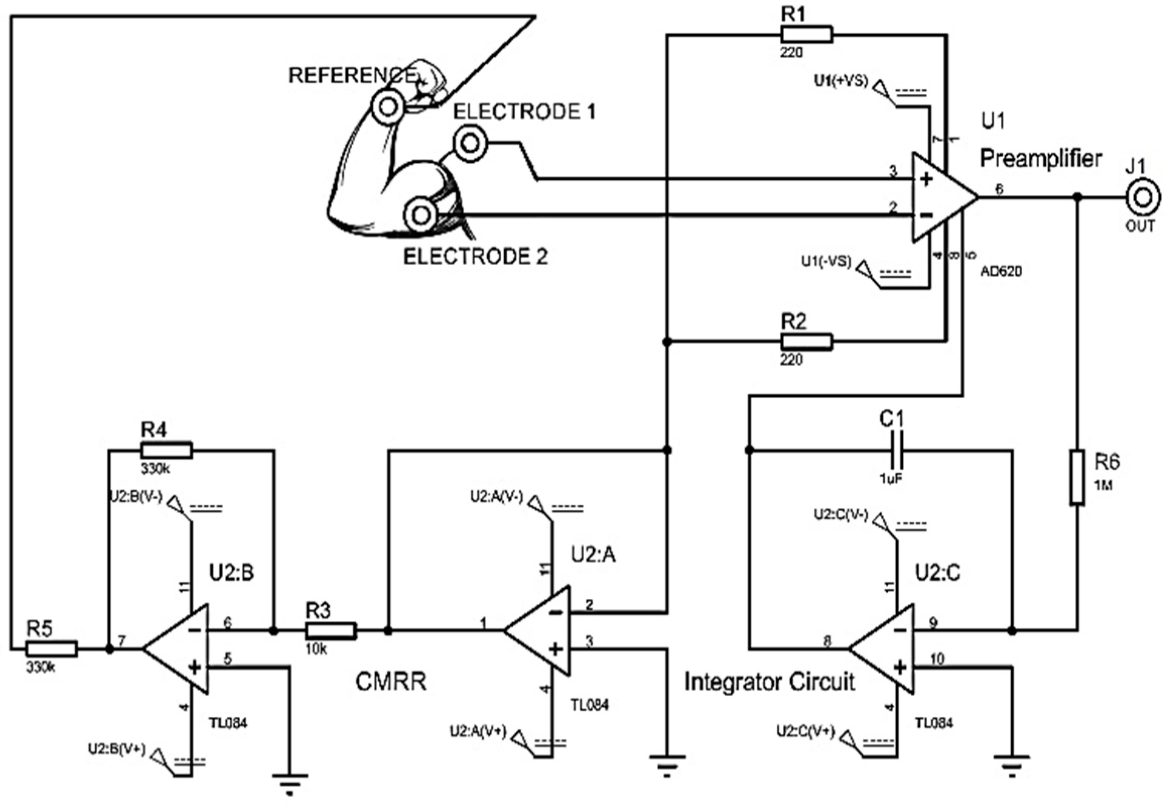
An instrumentation amplifier CI AD620 is implemented as a preamplification system to acquire the differential EMG signal with a gain of 500. A basal correction circuit is conditioned to eliminate the level of direct current (DC) caused by involuntary movements of the user or an incorrect connection of the electrodes. The circuit is a IC TL084 operational amplifier in its integrator configuration that is connected in feedback to the
and
outputs of the instrumentation amplifier, as shown in
Figure 4, implementing a high pass filter that eliminates the DC bias voltage and preventing op amps from reaching their maximum power limits.
- B.
Analog Filter
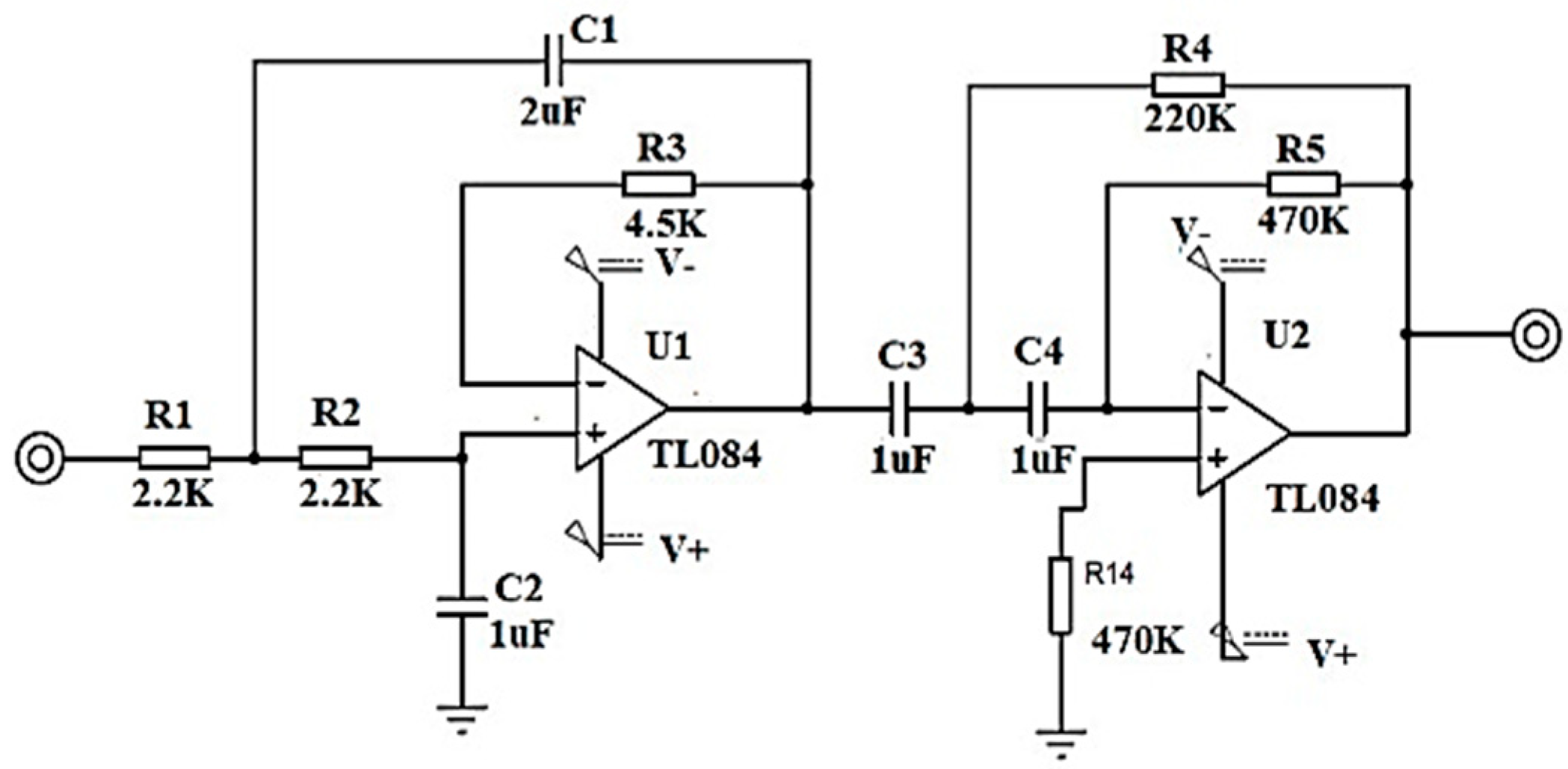
To filter the frequency components that are not within the bandwidth of the EMG signal, a range from 0.5 Hz to 5 KHz, a second order bandpass filter in Butterworth configuration with unity gain is designed, with a ratio of 40 dB per decade using high impedance TL084 operational amplifiers, precision resistors and electrolytic capacitors; see
Figure 5.
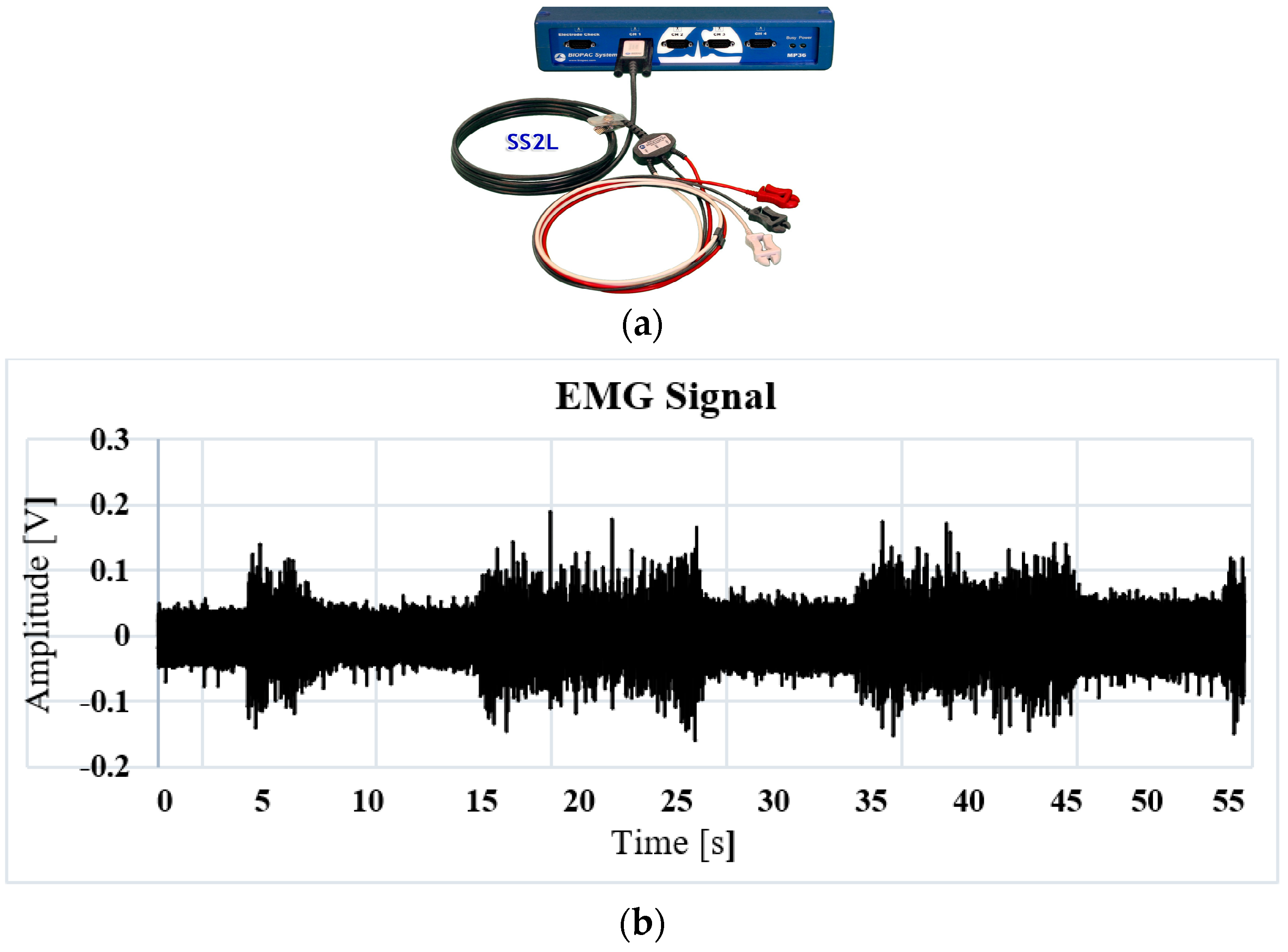
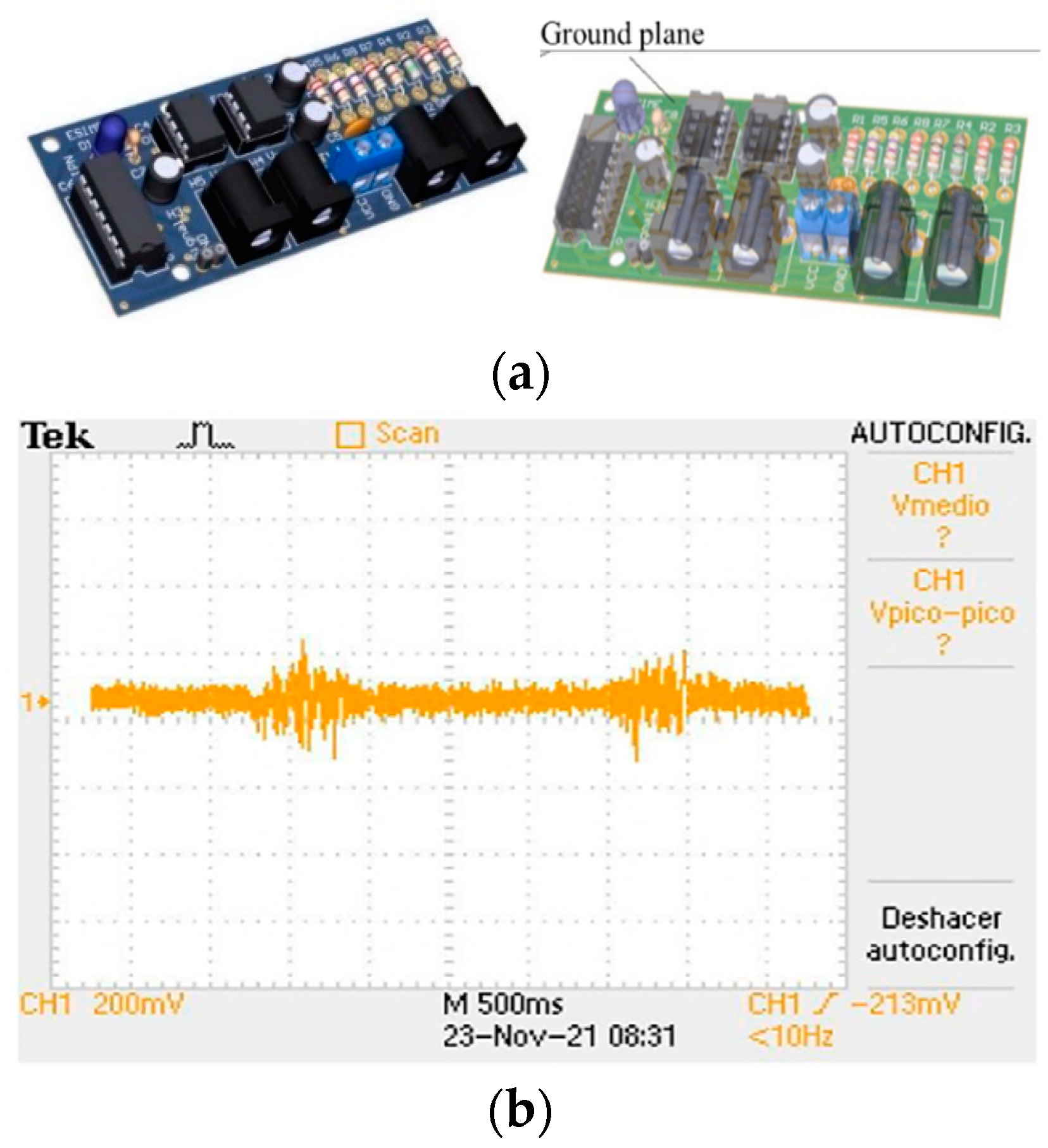
The output of the analog filter stage is connected to the absolute voltage input of a DAQ6009 acquisition card connected via USB port to a laptop, with a sample rate of 10KHz. An acquisition card with a ground plane is designed to decrease inductive noise, as indicated in
Figure 6a.
Figure 6b shows the response of the acquisition card in the Tektronix
® oscilloscope. Analog noise is observed, which is subsequently eliminated by means of a digital filter.
- C.
Digital Filter
Due to the acquisition system being subject to the interference of electromagnetic noise induced by lamps or some other external device, and in order to digitally tune the response of the filter, the design of a digital low pass filter is implemented. First, the analog/digital conversion is done with the National Instrument DAQ6009 card at an acquisition frequency of 10 KHz at 9600 bauds with 11 bits of resolution. The procedure consists of obtaining samples of the continuous signal at instants of time, defining , where is the sampling period.
The response of the digital first order low pass filter is obtained with the aim of reducing the computational cost when applying the filter in real time. The filter configuration is indicated in
Figure 7, indicating its response in terms of the complex frequency
. In Equation (1), the filter response is plotted as a function of the complex discrete frequency
.
In Equation (2) the filter equation is indicated as a function of the discrete variable
by means of difference equations when implementing the inverse z-transform of Equation (1).
To obtain the value of the cutoff frequency
and tune the digital filter, the Discrete Fourier Transform (FFT) is implemented. First, the EMG signal is digitized by means of a convolution with a Dirac delta pulse train as a function of time, where
is a signal represented in an exponential Fourier series, as in Equation (3).
represents the amplitude of the signal energy.
The frequency spectrum analysis is performed by applying the Fourier Transform on the discrete signal
, obtaining as a result a train of delta functions in frequency
, as indicated by Equation (4), whose amplitude is determined by the weighting of coefficients
, through the results of the spectrum in Frequency. The component that provides more energy to the signal is calculated; thus, the frequency of the induced noise is determined, and the cutoff frequency is obtained with precision
for the design of the digital filter.
Figure 8 is the result of the implementation of the digital filter in the acquisition of the EMG signal.
- D.
Multiclass Classifier: One Hot Encoding
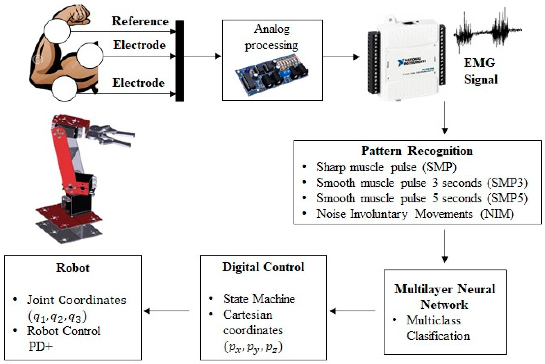
In this section, the method used is presented so that, in real time, the movements determined through the EMG interface are executed on a manipulator robot. An intelligent system for muscle contraction classification was implemented. Using a Multilayer Neural Network (MNN), a model is obtained that identifies four different classes of muscle contraction. The first class is described as Sharp muscle pulse (SMP), the second class as Smooth muscle pulse 3 s (SMP3), the third class as Smooth Muscle Pulse 5 s (SMP5) and, finally, the fourth class is described as Noise Involuntary Movements (NIM). These signals are classified using the One-Hot Encoding technique that labels the waveform of each signal with an integer. Thus, the digital inputs of a state machine are obtained, which determine the predetermined position of a manipulator robot with three degrees of freedom in the Cartesian plane (x, y, z) inside the robot workspace. In
Figure 9, the architecture of the HMI based on EMG is presented.
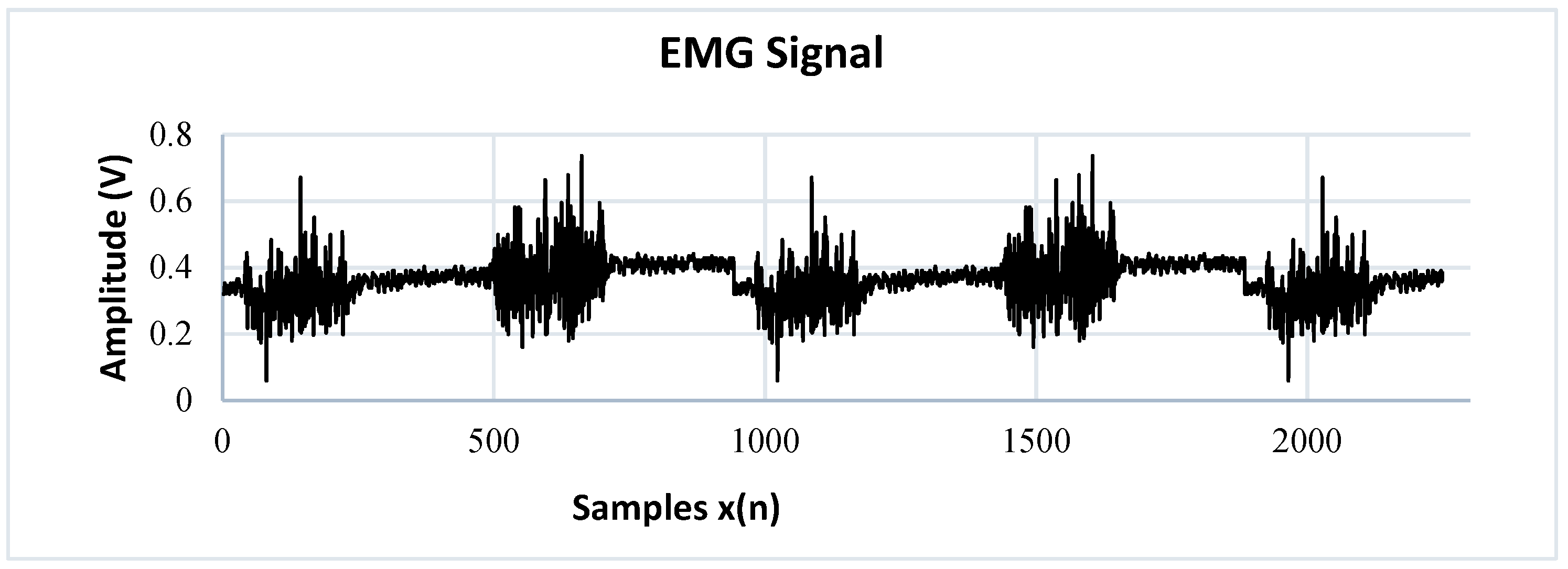
To perform the identification of patterns in the EMG signal of a single channel, they are divided into action potentials with different time intervals. The SMP (Sharp Muscle Pulse) class has an instantaneous contraction interval of 1 s and muscle relaxation intervals of 5 s. The SMP3 (Smooth Muscle Pulse 3 s) class has a contraction interval of 3 s and muscle relaxation intervals of 5 s. The SMP5 (Smooth Muscle Pulse 5 s) class has a muscle contraction interval of 5 s and muscle relaxation intervals of 5 s. The NIM (Noise Involuntary Movements) class is a class that records the resting state of users as well as involuntary arm movements recorded during acquisition. All these samples are stored in a vector called
.
Figure 10 indicates the waveform of each class. The SMP, SMP3 and SMP5 classes indicate a position change control order in the manipulator robot, while the NIM class indicates a total stop state, so the MNN has as inputs the different signals identified in classes stored in the vector
. An integer is assigned to each class through supervised training; this labeling is stored in a vector called
, where n is the total number of samples.
- E.
Multiclass Classifier: Multilayer Neural Network
In this section, the implementation of an intelligent system for the classification of EMG signals is presented. The representation of the multilayer neural network is presented in
Figure 11, where
is the vector of the
inputs,
represents the polarization of S neurons,
represents the net inputs of each of the S neurons and
is the matrix of synaptic weights.
The first stage consists of data normalization because the EMG signals have different voltage thresholds. The description of this procedure is presented in Equation (5), where
represents the data set of the EMG signal by means of a vector of an acquisition channel. The mean of the data is subtracted, with a standard deviation equal to 1 to minimize the computational cost when the network performs the learning process.
Algorithm 1 describes the pseudocode for the implementation of the Neural Network in Python; the training consists of assigning to each sample the value of a constant that is stored in the vector
. This vector is the desired result for each class and has the same dimensions as the input vector
.
| Algorithm 1: Multilayer Perceptrón algorithm implemented for the EMG |
| 1 |
| 2 |
| |
| 3 /*** output vector T where the labeling value is stored by one-hot-encoding of each the classes***/ |
| 4 |
| |
| 5 |
| |
| 6 |
| |
| 7 /**Divide p into a test ( and a training set **/ |
| |
| 8 |
| 9 |
| |
| 10 /**Random Initialization**/ |
| 11 |
| |
| 12 |
| 13 |
| |
| 14 |
| |
| 15 |
| 16 //ReLu activation function |
| |
| 17 |
| 18 //Softmax activation function |
| |
| 19 |
| |
| 20 |
| 21 /**Loss function (categorial cross entropy**/ |
| 22 |
| |
| 22 |
| 24 |
| |
| 25 |
| 26 |
| |
| 27 |
| 28 |
| 29 |
| 30 |
In
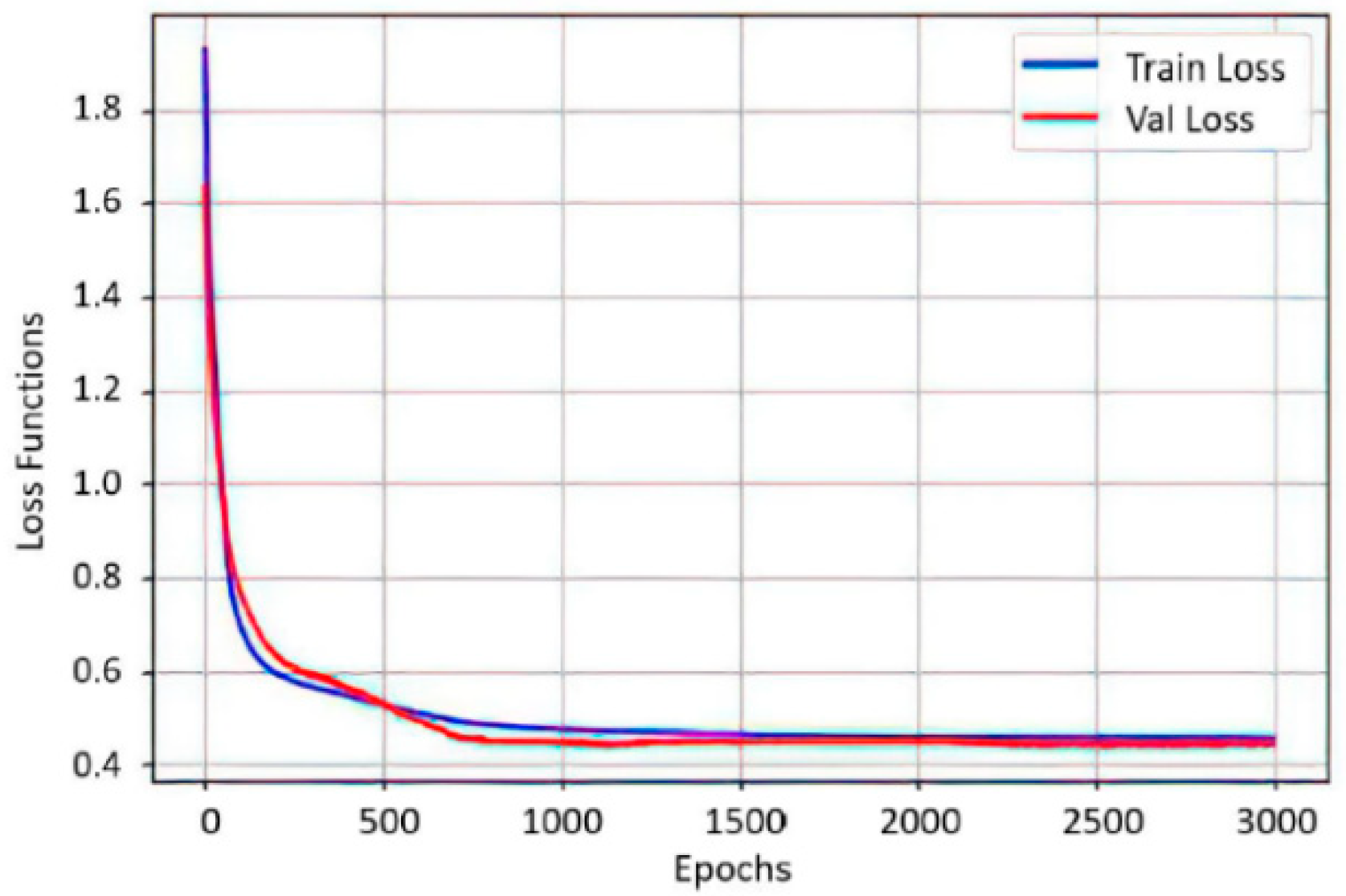
Figure 12, an association between the precision of the neural network with new data
and the value of the loss function
after 3000 epochs is presented. Both graphs have a tendency to zero as training progresses, indicating a correct functioning of the optimizer. In [
22], the authors designed multiclass classification on two channels of electrooculography signals and controlled an omnidirectional mobile robot in the X, Y plane. In this work, it is shown that, according to the muscle contraction time, the multiclass classification allows for the control of robotic systems that work in space (X, Y, Z) and that are adaptive to the individual characteristics of the user, achieving a personalization of the Interface.
The obtained values of the synaptic weights
W and the polarization vector b of the two neurons, after 3000 epochs:
Once the model recognizes each of the classes by means of integers, a comparison system is implemented using the premise, “If the Network output is: (integer) [
1,
2,
3,
4] then 1 is enabled when the network recognizes the waveform that corresponds to each label, otherwise it is 0”. This process allows for a combination of digital pulses for the activation of a state machine.
- F.
State Machine
The combination of digital signals obtained from the pattern recognition of the neural network by means of class classification allows for the transition change of a state machine. A Mealy-type machine is implemented, which generates an output based on its current state and an input. Three finite sets determined by the inputs, outputs and states are defined.
In
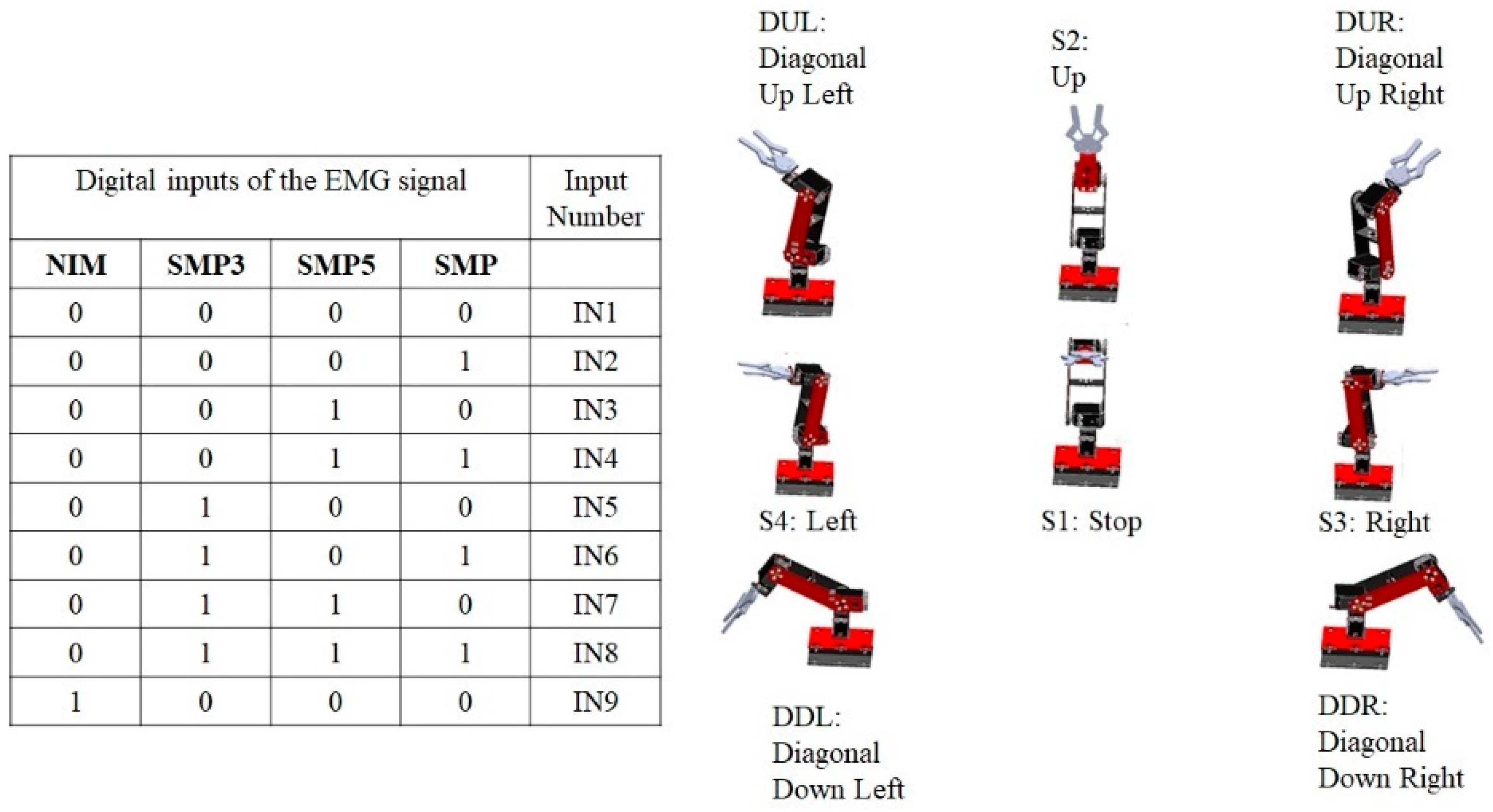
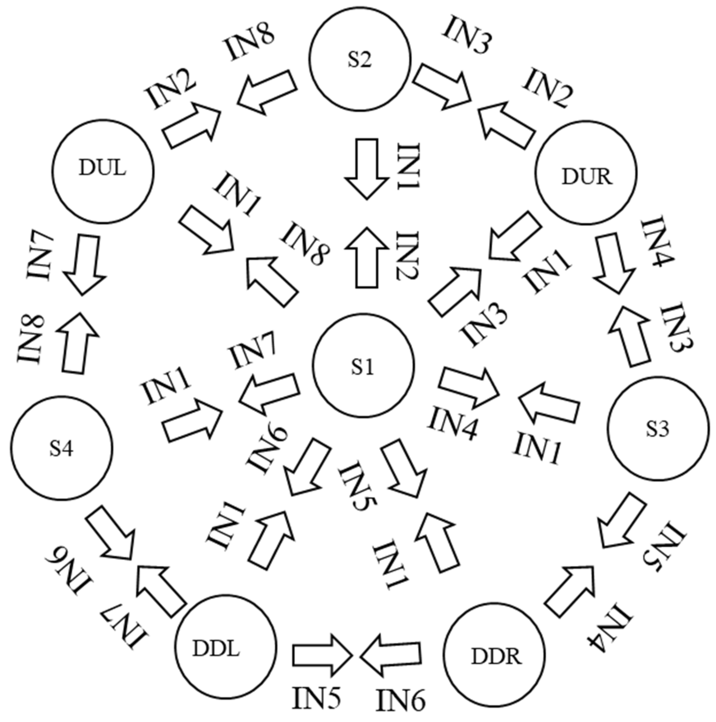
Figure 13, the transitions of the digital inputs are indicated and the NIM class is represented as the most significant bit. In the next position the SMP3 class is, then the SMP5 class and finally the SMP class, so that there is an input 4 bits for transition change. Each of the states indicates a predetermined position of the manipulator robot with three degrees of freedom in Cartesian coordinates
. Subsequently, these coordinates are converted to joint coordinates
using the inverse kinematics of the manipulator robot. There is an input IN9 that, when detecting a status at 1 of noise or involuntary movements, completely deactivates the operation of the robot; this is taken as a security measure to not activate the robot when this class of signals occurs.
In
Figure 14, the designed machine has eight possible states for muscle movement, with four digital inputs corresponding to the high and low pulses of the Neural Network recognition.
Table 1 describes the position in Cartesian coordinates of each of the robot states.
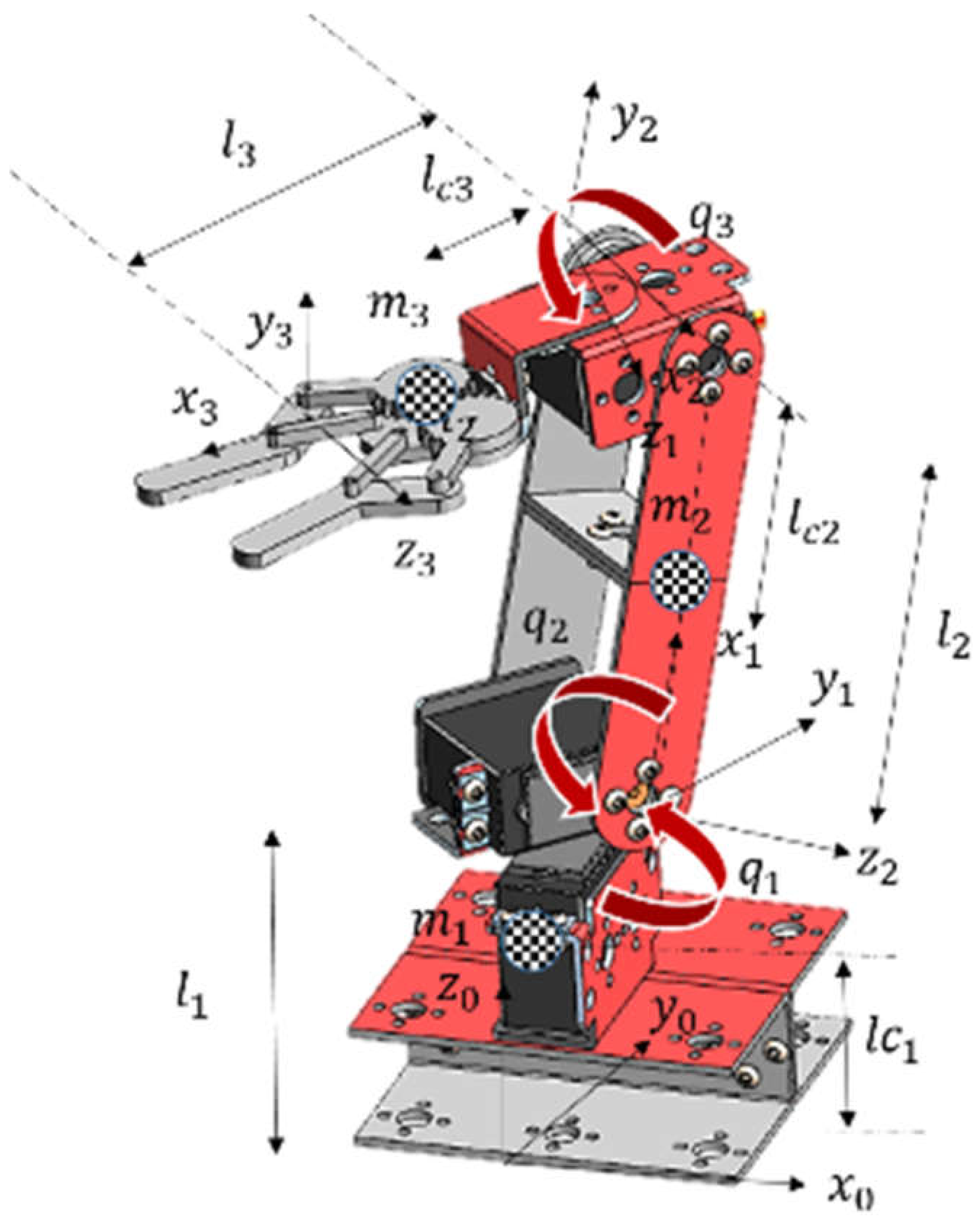
The selected robot is an anthropomorphic robot with three degrees of freedom and rotational joints whose operation is similar to the human arm (
Figure 15), where
and
represent the total length of the links,
and
represent the length from the initial end to the center of mass of each of the links that make up the robot,
and
are the values of the center of mass of each link,
represent the cartesian axes indicating the orientation of the position and
and
represent each degree of freedom of each rotational joint of the robot.
To determine the workspace of the anthropomorphic robot, the calculation of the forward kinematics is performed, which determines the position of the end effector in Cartesian coordinates
based on joint coordinates
indicated in Equation (6). These equations are fundamental for the calculation of the robot dynamics.
Because the state machine has the coordinates of the end effector position in meters for each of the Cartesian axes
y
, the inverse kinematics of the robot defined in Equation (7), these equations determine the value of the position in radians for each of the degrees of freedom
.
where:
To implement the PD+ position tracking control algorithm, use the dynamic model defined in Equation (8).
Inertia Matrix
Coriolis Matrix
Viscous friction vector
Torque Vector
where
is a positive definite symmetric matrix of
called the inertia matrix, with
being the moments of inertia of the rigid links of the mechanical structure of the robot,
is an
vector called the vector of centrifugal and Coriolis forces,
is an
vector that determines the viscous friction,
is an
vector of gravitational forces and
is the
vector that determines the torques and forces applied by the actuators at the joints.
- G.
Position Control
As a result of the cartesian coordinates
obtained from the classifier by means of a Multilayer Neural Network and assigned to a discrete event by means of a state machine, the desired Cartesian coordinates for the robot are obtained, which are transformed to joint coordinates
from inverse kinematics. These values are the inputs for the PD+ type position control system. [
15].
The PD+ control with gravity compensation, defined in Equation (9) by
, is an algorithm that includes proportional control of the position error
and velocity error proportional control
, where
are the proportional and derivative gains, respectively, both are positive definite matrices, and the full dynamics of the robot are added. In the structure of this scheme, the trajectory of position, velocity and desired acceleration is involved,
.
The objective of this control is to find a torque value,
, such that it satisfies the expression indicated in Equation (10).
where
is the following error and is defined as
, and
is the velocity error, given by
.
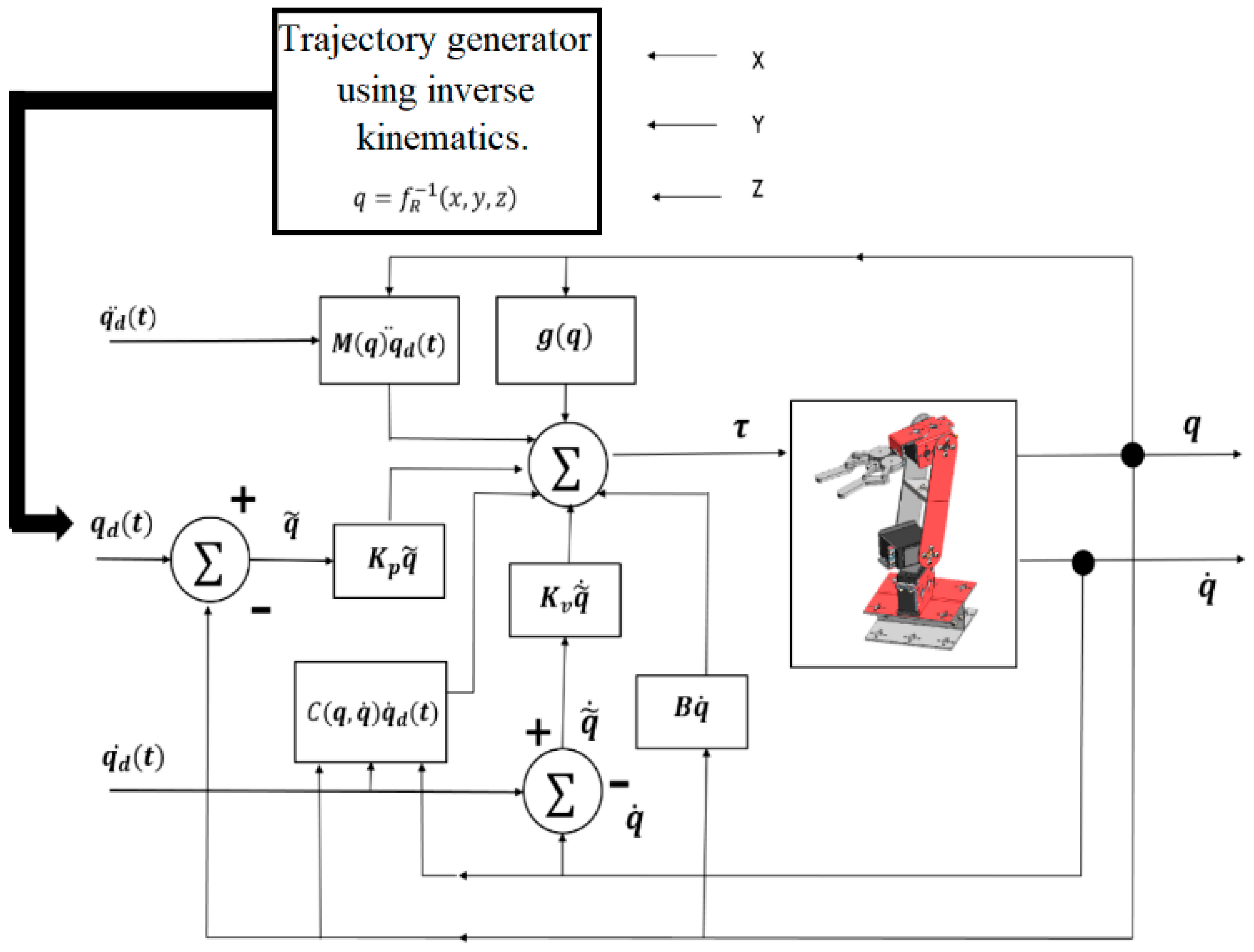
Figure 16 indicates the block diagram of the implemented PD+ control.
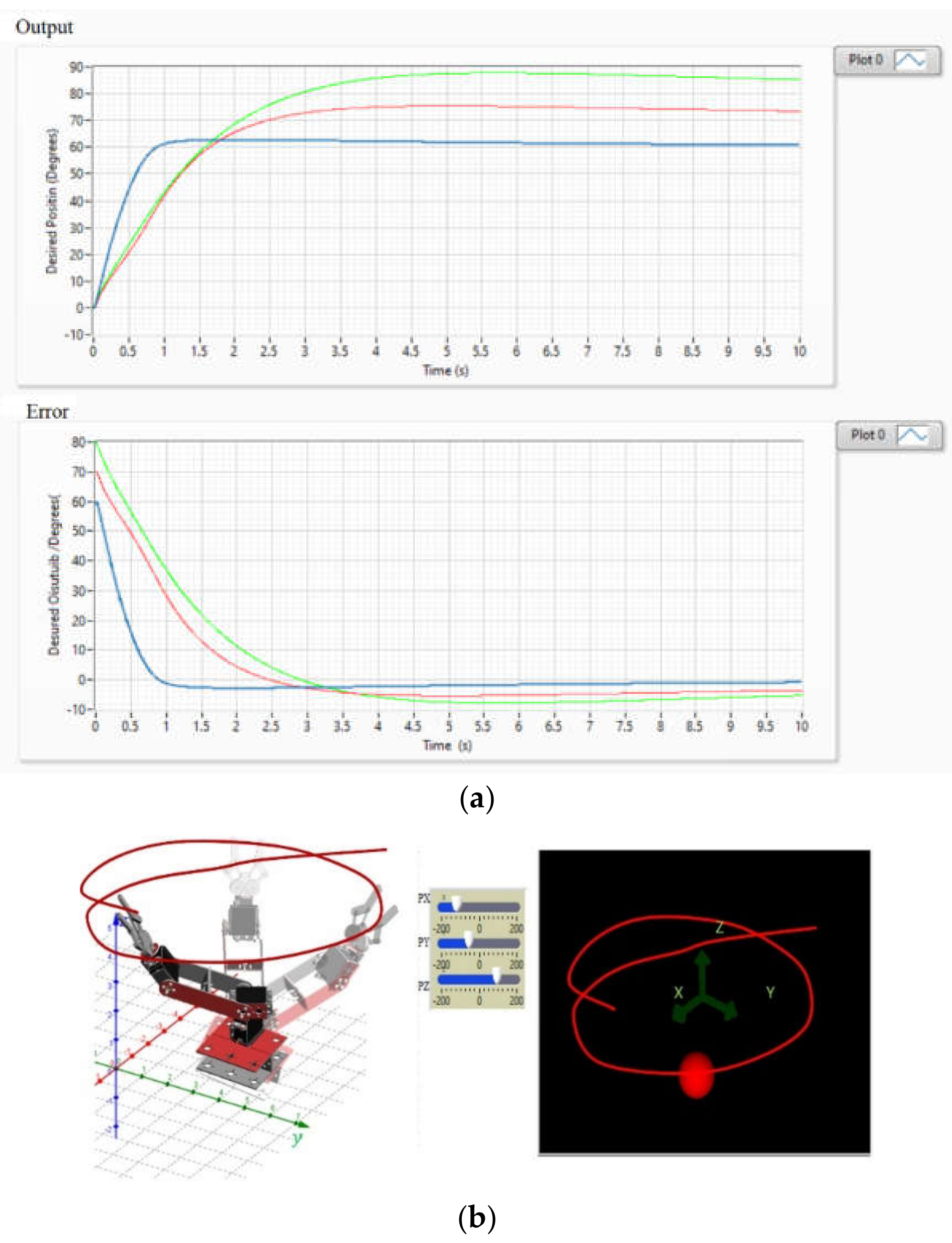
Figure 17a shows the behavior of the zero-position error trend in each joint coordinate of the robot whose Cartesian coordinate is assigned by the state machine. The operation of the control when reaching the desired joint position is also presented.
Figure 17b shows the virtual simulation of the robot applying the PD+ control for the generation of trajectories through the interaction of the EMG signal.
A graphical user interface is designed as indicated in
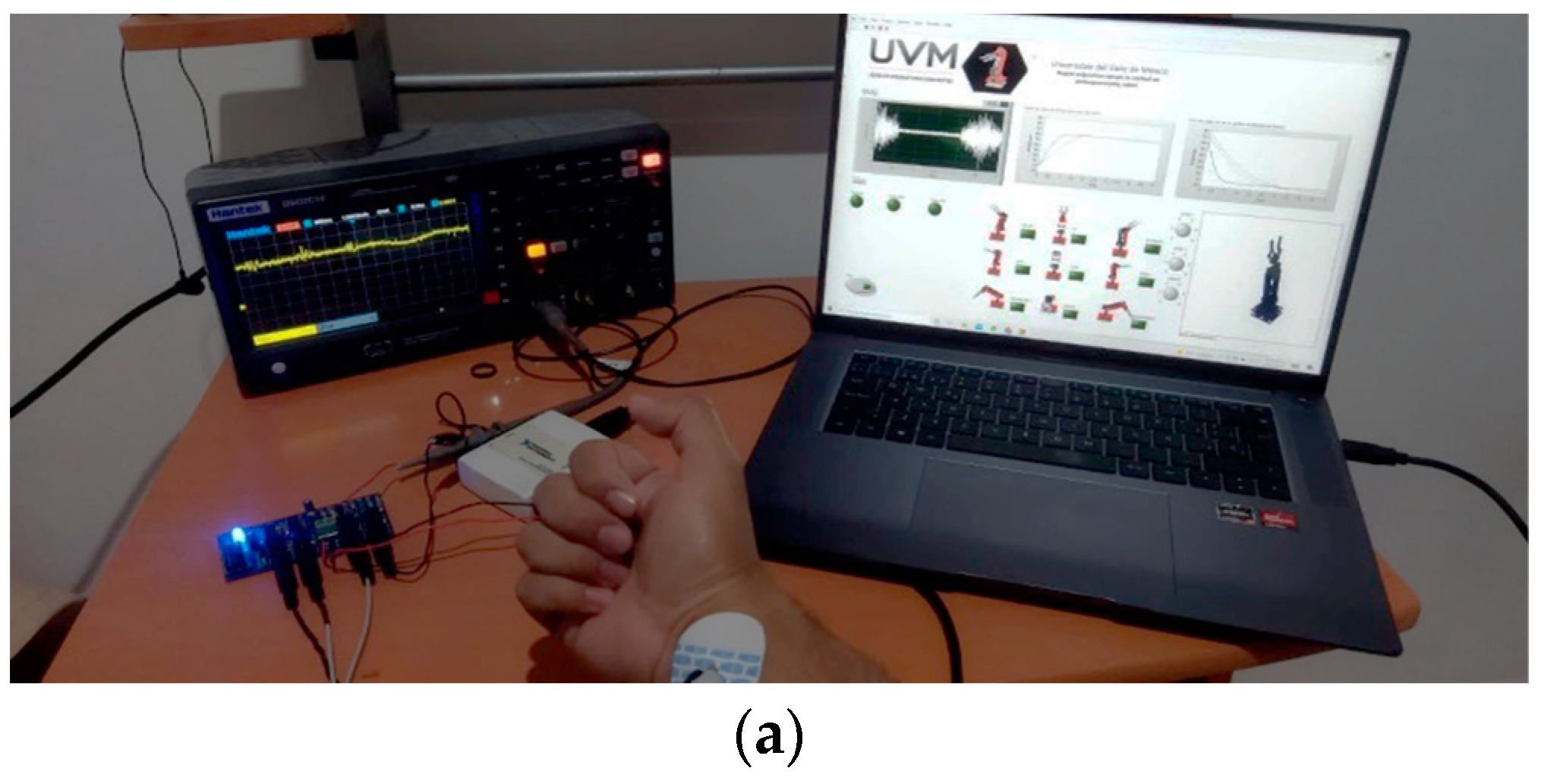
Figure 18b with visual feedback of the EMG signal, the result of the state machine by means of a green indicator that indicates the position detected of the MNN’s classification, the control curves resulting from the implemented PD+ and a simulation of the virtual robot that indicates the position of the end effector. In
Figure 18b, the user connection and the operation of the interface to calculate the response time metrics are indicated.
