
A Wideband Circularly Polarized Magnetoelectric Dipole Antenna for 5G Millimeter-Wave Communications


Abstract
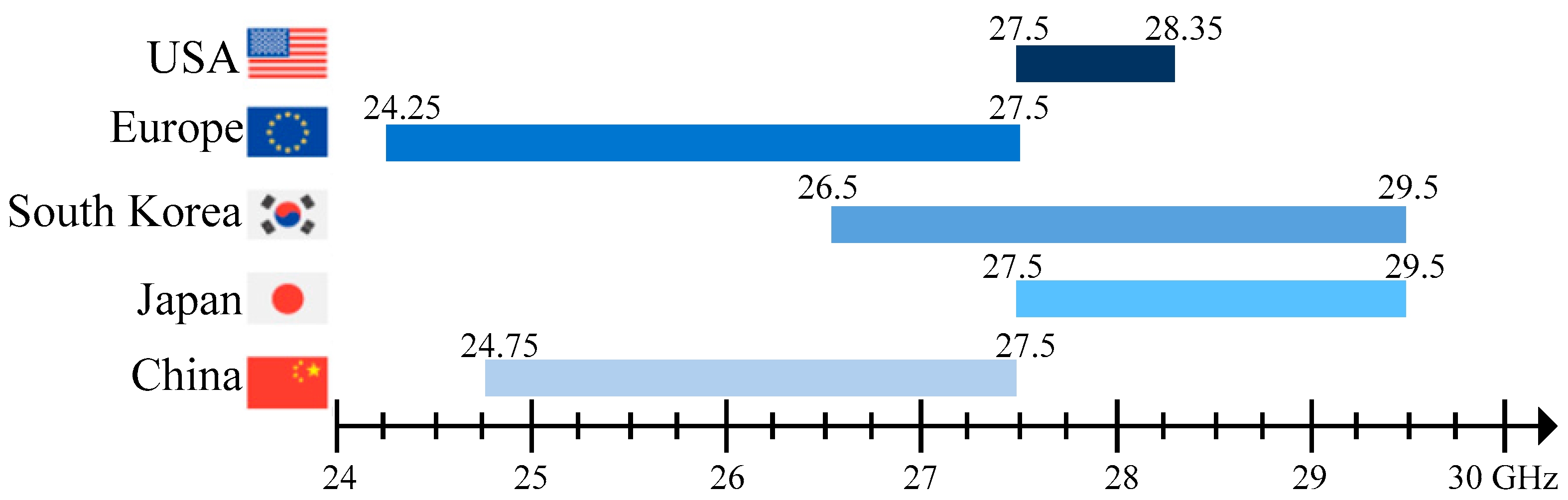
:1. Introduction
2. CP ME Antenna Design and Analysis
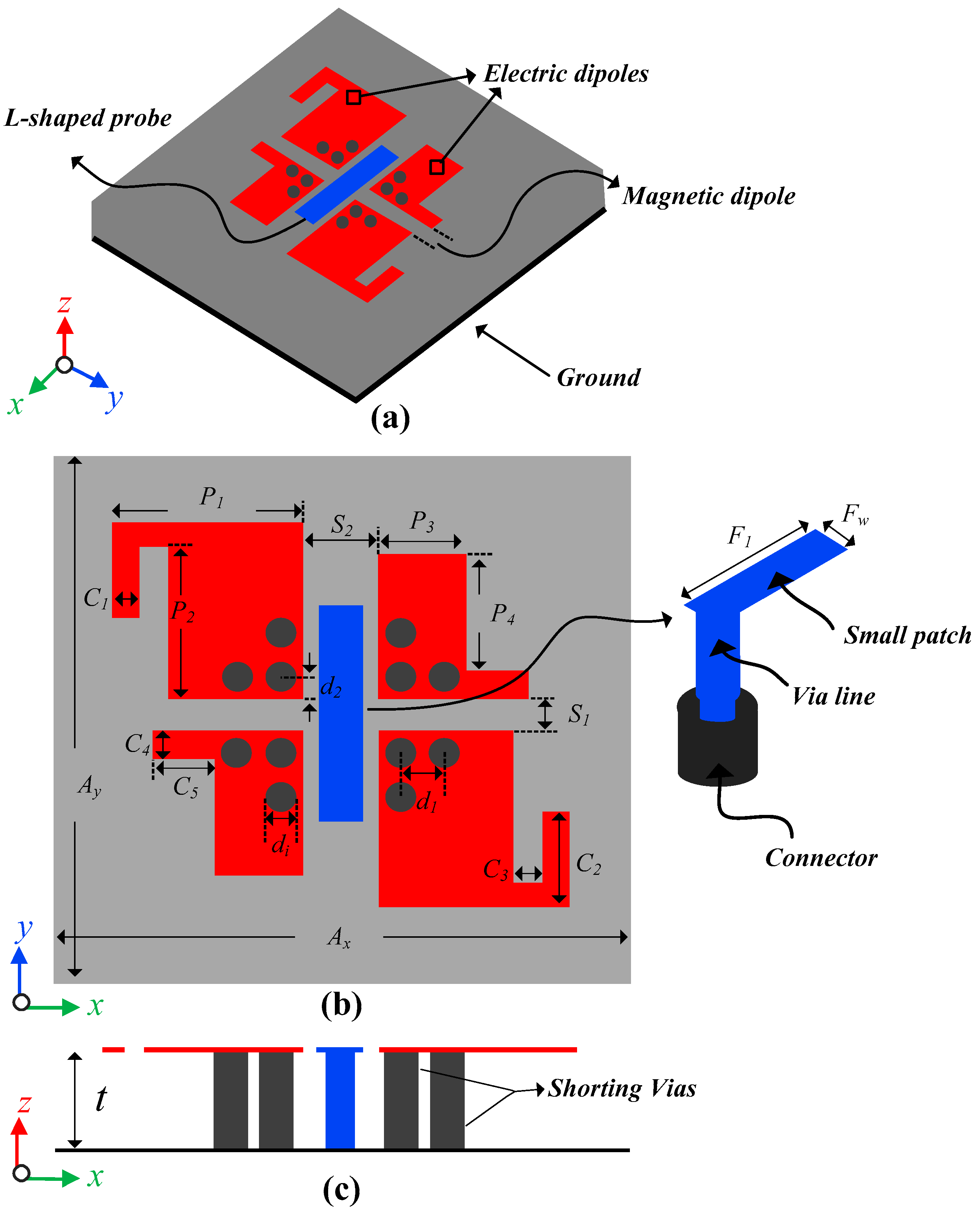
2.1. Antenna Geometry
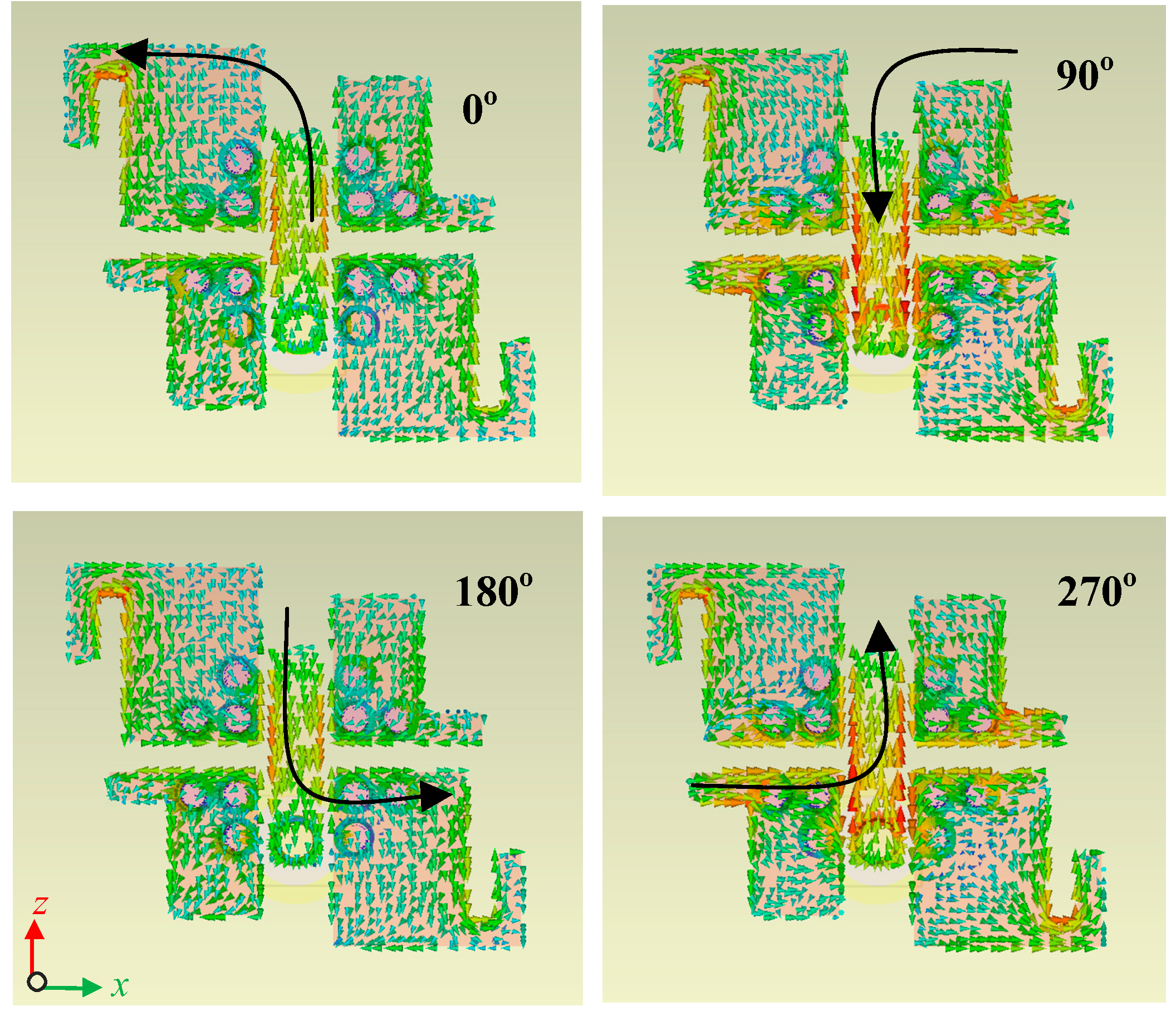
2.2. CP Mechanism
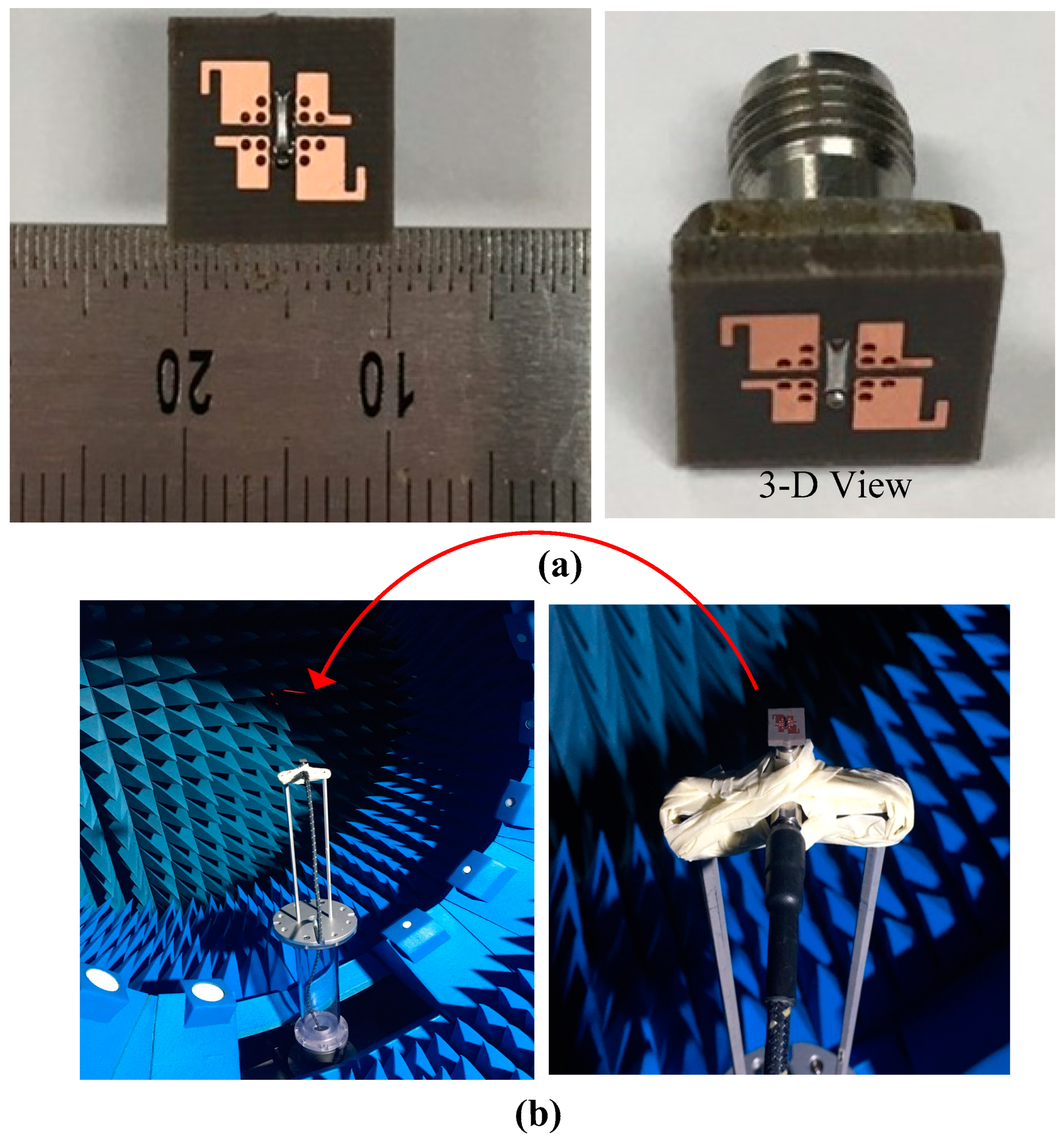
3. Results and Discussion
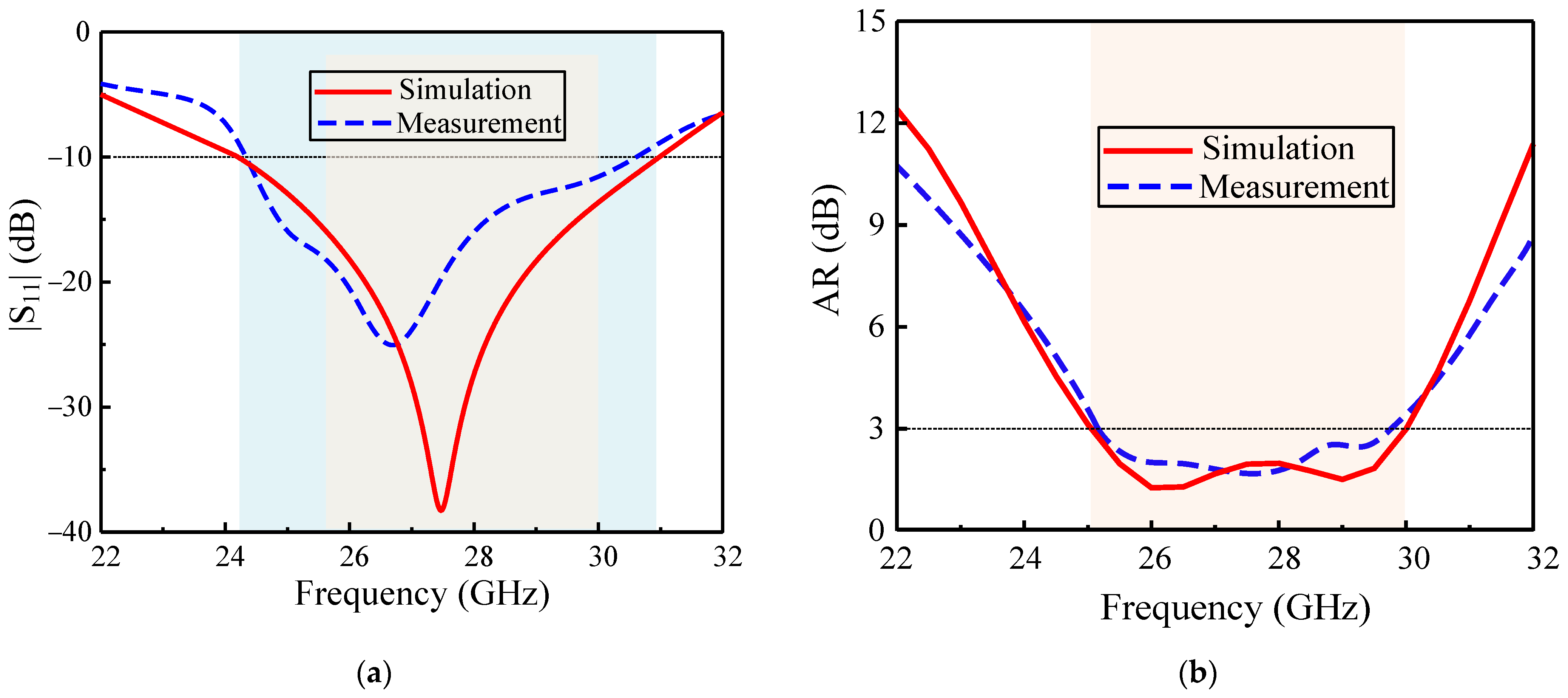
3.1. S-Parameters and Axial Ratio
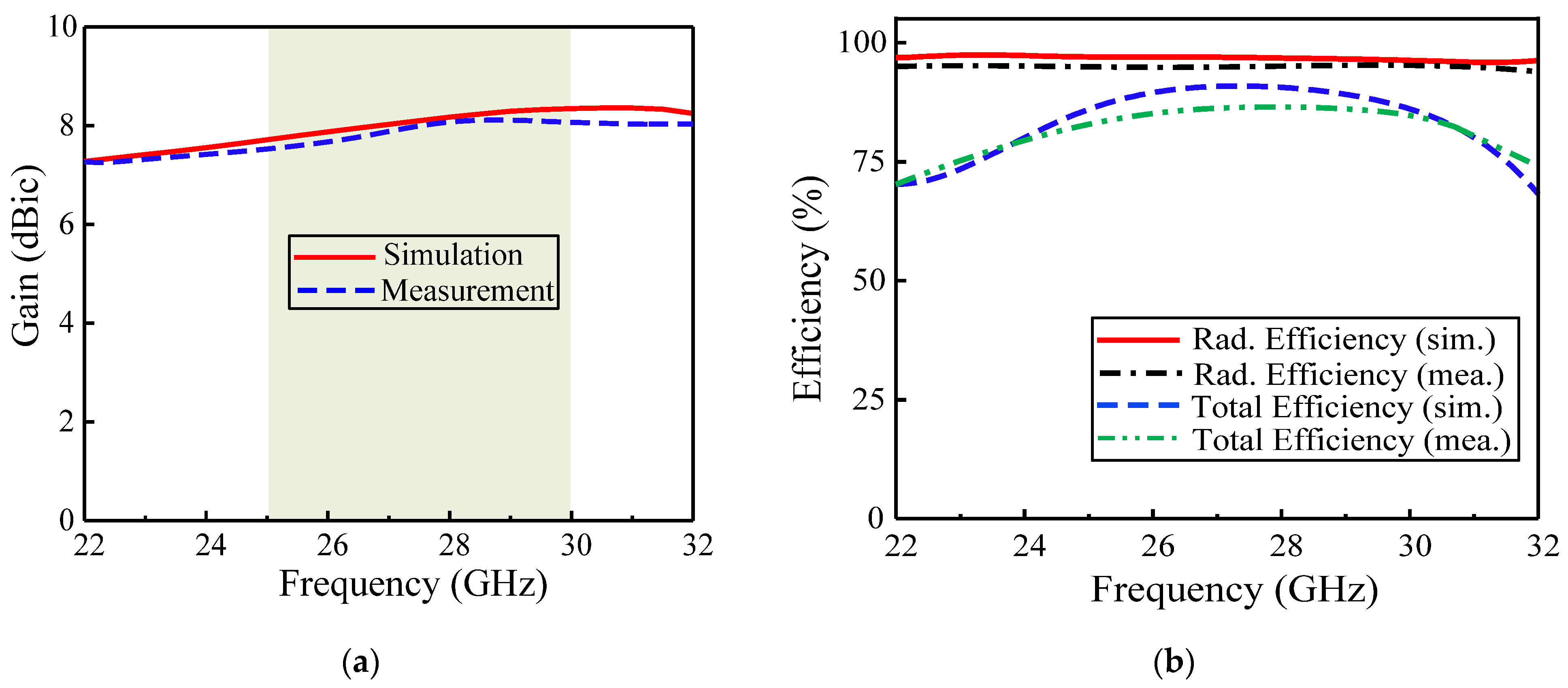
3.2. Broadside Gain and Efficiency
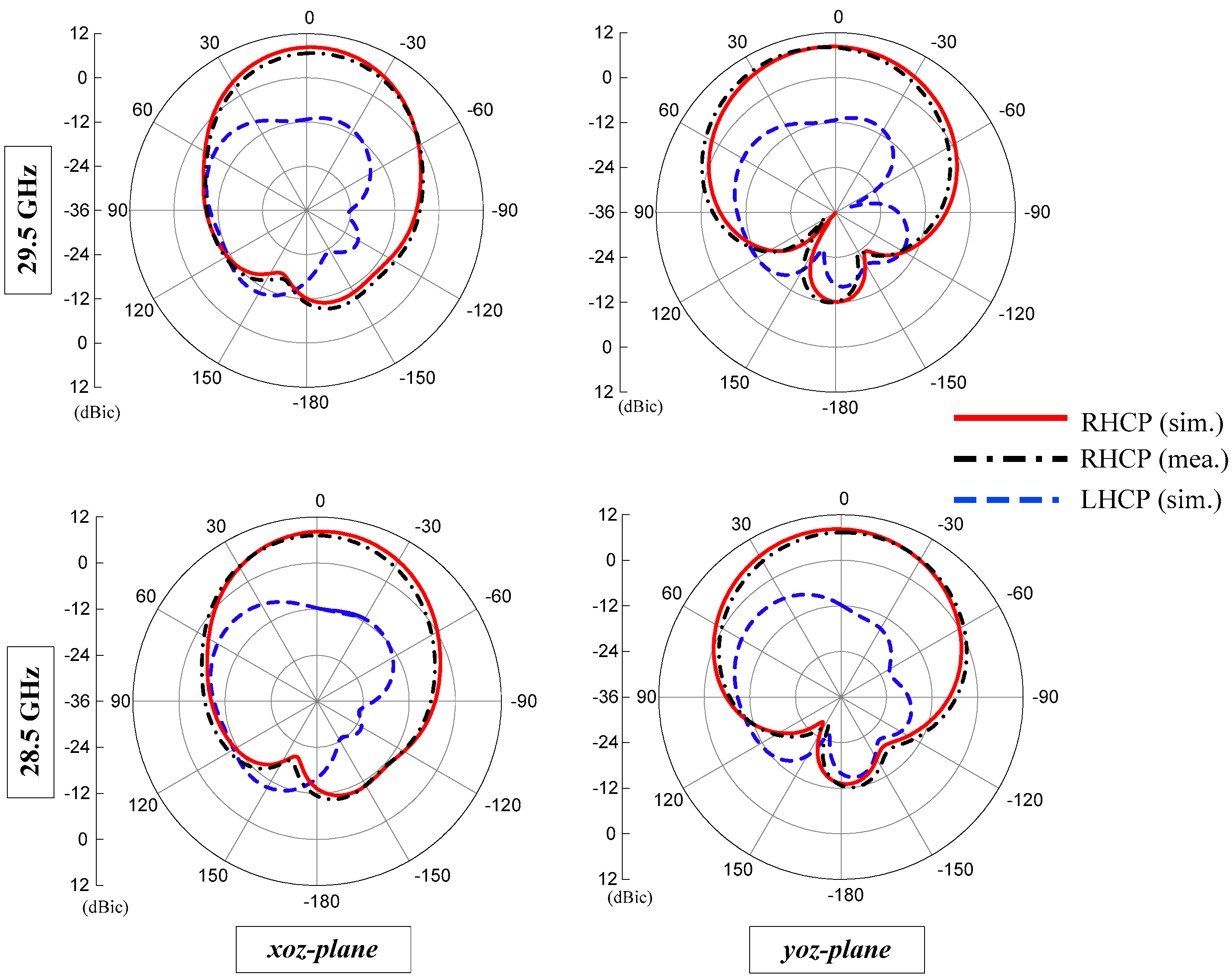
3.3. Radiation Patterns
3.4. Performance Comparison
4. Conclusions
Author Contributions
Funding
Institutional Review Board Statement
Informed Consent Statement
Data Availability Statement
Acknowledgments
Conflicts of Interest
References
- Dangi, R.; Lalwani, P.; Choudhary, G.; You, I.; Pau, G. Study and investigation on 5G technology: A systematic review. Sensors 2022, 22, 26. [Google Scholar] [CrossRef] [PubMed]
- 5G Frequency Bands. Available online: https://halberdbastion.com/technology/cellular/5g-nr/5g-frequency-bands/n257-28-ghz (accessed on 5 January 2022).
- Nalanagula, R.; Darimireddy, N.K.; Kumari, R.; Park, C.-W.; Reddy, R.R. Circularly polarized hybrid dielectric resonator antennas: A brief review and perspective analysis. Sensors 2021, 21, 4100. [Google Scholar] [CrossRef] [PubMed]
- Sabban, A. Wearable circular polarized antennas for health care, 5G, energy harvesting, and IoT systems. Electronics 2022, 11, 427. [Google Scholar] [CrossRef]
- Trinh, L.H.; Truong, N.V.; Ferrero, F. Low cost circularly polarized antenna for IoT space applications. Electronics 2020, 9, 1564. [Google Scholar] [CrossRef]
- Nguyen, H.Q.; Le, M.T. Multiband ambient RF energy harvester with high gain wideband circularly polarized antenna toward self-powered wireless sensors. Sensors 2021, 21, 7411. [Google Scholar] [CrossRef]
- Hussain, N.; Jeong, M.; Park, J.; Kim, N. A Broadband circularly polarized Fabry-Perot resonant antenna using a single-layered PRS for 5G MIMO applications. IEEE Access 2019, 7, 42897–42907. [Google Scholar] [CrossRef]
- Zhang, C.; Chen, H. A broadband circularly polarized substrate integrated antenna with dual magnetoelectric dipoles coupled by crossing elliptical slots. In Proceedings of the 2018 IEEE 18th International Conference on Communication Technology (ICCT), Chongqing, China, 8–11 October 2018; pp. 564–567. [Google Scholar]
- Nkimbeng, C.H.; Wang, H.; Park, I. Coplanar waveguide-fed bidirectional same-sense circularly polarized metasurface-based antenna. J. Electromagn. Eng. Sci. 2021, 21, 210–217. [Google Scholar] [CrossRef]
- Zambak, M.F.; Yasin, M.N.M.; Adam, I.; Iqbal, J.; Osman, M.N. Higher-order-mode triple band circularly polarized rectangular dielectric resonator antenna. Appl. Sci. 2021, 11, 3493. [Google Scholar] [CrossRef]
- Luk, K.M.; Wong, H. A new wideband unidirectional antenna element. Int. J. Microw. Opt. Technol. 2006, 1, 35–44. [Google Scholar]
- Tan, W.; Xiao, Y.; Li, C.; Zhu, K.; Luo, H.; Sun, H. A wide-band high-efficiency hybrid-feed antenna array for mm-Wave wireless systems. Electronics 2021, 10, 2383. [Google Scholar] [CrossRef]
- Wang, Y.; Tan, W.; Zhu, K.; Luo, H.; Zhao, G.; Sun, H. Design of A Ka-band 3D-printed dual-polarization magnetoelectric dipole antenna array with low sidelobe. Electronics 2021, 10, 2969. [Google Scholar] [CrossRef]
- Mak, K.M.; Luk, K.M. A circularly polarized antenna with wide axial ratio beamwidth. IEEE Trans. Antennas Propag. 2009, 57, 3309–3312. [Google Scholar]
- Ta, S.X.; Park, I. Crossed dipole loaded with magneto-electric dipole for wideband and wide-beam circularly polarized radiation. IEEE Antennas Wirel. Propag. Lett. 2014, 14, 358–361. [Google Scholar] [CrossRef]
- Wu, S.; Zhao, J.; Xu, J. A circularly polarized low-profile magnetoelectric dipole antenna. Microw. Opt. Technol. Lett. 2021, 63, 2852–2858. [Google Scholar] [CrossRef]
- Kang, K.; Shi, Y.; Liang, C.-H. A wideband circularly polarized magnetoelectric dipole antenna. IEEE Antennas Wirel. Propag. Lett. 2017, 16, 1647–1650. [Google Scholar] [CrossRef]
- Li, M.; Luk, K.-M. A wideband circularly polarized antenna for microwave and millimeter-wave applications. IEEE Trans. Antennas Propag. 2014, 62, 1872–1879. [Google Scholar] [CrossRef]
- Ruan, X.; Qu, S.-W.; Zhu, Q.; Ng, K.B.; Chan, C.H. A complementary circularly polarized antenna for 60-GHz applications. IEEE Antennas Wirel. Propag. Lett. 2016, 16, 1373–1376. [Google Scholar] [CrossRef]
- Bai, X.; Qu, S.-W.; Yang, S.; Hu, J.; Nie, Z.-P. Millimeter-wave circularly polarized tapered-elliptical cavity antenna with wide axial-ratio beamwidth. IEEE Trans. Antennas Propag. 2015, 64, 811–814. [Google Scholar] [CrossRef]
- Zhu, Q.; Ng, K.-B.; Chan, C.H. Printed circularly polarized spiral antenna array for millimeter-wave applications. IEEE Trans. Antennas Propag. 2016, 65, 636–643. [Google Scholar] [CrossRef]
- Ding, X.; Wu, S.; Yang, G.; Lan, H. Dual Circularly polarized wideband magneto-electric dipole antenna for wireless applications. Prog. Electromagn. Res. Lett. 2022, 102, 27–36. [Google Scholar] [CrossRef]
- Wang, Y.F.; Wu, B.; Zhang, N.; Zhao, Y.T.; Su, T. Wideband circularly polarized magneto-electric dipole 1x2 antenna array for millimeter-wave applications. IEEE Access 2020, 8, 27516–27523. [Google Scholar] [CrossRef]
- Xiang, L.; Wu, F.; Yu, C.; Jiang, Z.H.; Yao, Y.; Hong, W. A wideband circularly polarized magneto-electric dipole antenna array for millimeter-wave applications. IEEE Trans. Antennas Propagation. 2021. [Google Scholar] [CrossRef]
- Feng, B.; Lai, J.; Chung, K.L.; Chen, T.Y.; Liu, Y. A compact wideband circularly polarized magneto-electric dipole antenna array for 5G millimeter-wave application. IEEE Trans. Antennas Propag. 2020, 68, 6838–6843. [Google Scholar] [CrossRef]
- Causse, A.; Rodriguez, K.; Bernard, L.; Sharaiha, A.; Collardey, S. Compact bandwidth enhanced cavity-backed magneto-electric dipole antenna with outer G-shaped probe for GNSS bands. Sensors 2021, 21, 3599. [Google Scholar] [CrossRef]
- Hussain, N.; Jeong, M.; Abbas, A.; Kim, N. Metasurface-based single-layer wideband circularly polarized MIMO antenna for 5G millimeter-wave systems. IEEE Access 2020, 8, 130293–130304. [Google Scholar] [CrossRef]
- Hussain, N.; Jeong, M.; Abbas, A.; Kim, T.; Kim, N. A metasurface-based low-profile wideband circularly polarized patch antenna for 5G millimeter-wave systems. IEEE Access 2020, 8, 22127–22135. [Google Scholar] [CrossRef]
- Li, R.-L.; Fusco, V.F.; Nakano, H. Circularly polarized open-loop antenna. IEEE Trans. Antennas Propag. 2003, 51, 2475–2477. [Google Scholar]
- Askari, H.; Hussain, N.; Domin Choi, M.; Sufian, A.; Abbas, A.; Kim, N. An AMC-based circularly polarized antenna for 5G sub-6 GHz communications. CMC-Comput. Mater. Contin. 2021, 69, 2997–3013. [Google Scholar] [CrossRef]
- Lim, J.H.; Lee, J.W.; Lee, T.K. Cross-pol pattern effects of parabolic reflector antennas on the performance of spaceborne quad-pol SAR systems. J. Electromagn. Eng. Sci. 2021, 21, 218–227. [Google Scholar] [CrossRef]
- Lavdas, S.; Gkonis, P.K.; Zinonos, Z.; Trakadas, P.; Sarakis, L. An adaptive hybrid beamforming approach for 5G-MIMO mmWave wireless cellular networks. IEEE Access 2021, 9, 127767–127778. [Google Scholar] [CrossRef]


| Parameter | Value (mm) | Parameter | Value (mm) | Parameter | Value (mm) |
|---|---|---|---|---|---|
| t | 1.5 | P4 | 1.8 | C4 | 0.45 |
| F1 | 2.5 | S1 | 0.5 | C5 | 1 |
| Fw | 0.7 | S2 | 1 | di | 0.5 |
| P1 | 3 | C1 | 0.4 | d1 | 0.7 |
| P2 | 2.4 | C2 | 1.5 | d2 | 0.35 |
| P3 | 1.4 | C3 | 0.5 | Ax, Ay | 10 |
| Ref. | Antenna Type | Antenna Volume (λ03) | fc (GHz) | Polarization | 3 dB ARBW (%) | Peak Gain (dBic) |
|---|---|---|---|---|---|---|
| [8] | ME dipole antenna | 1.54 × 0.48 × 0.291 | 29 | CP | 4.8 | 5.1 |
| [16] | ME dipole antenna | 1.18 × 1.05 × 0.122 | 24 | CP | 12.8 | 7.8 |
| [17] | ME dipole antenna | 1.6 × 1.3 × 0.26 | 2.5 | CP | 71.5 | 8 |
| [18] | ME dipole antenna | 1.1 × 1.1 × 0.29 | 2.2 | CP | 47.7 | 8.6 |
| [19] | ME dipole antenna | 6 × 6 × 0.305 | 60 | CP | 23.4 | 8.6 |
| [20] | ME dipole antenna | 1.12 × 3.03 × 0.6 | 60 | CP | 11.6 | 10.4 |
| [21] | ME dipole antenna | 1 × 1 × 0.315 | 60 | CP | 21.9 | 7.9 |
| [22] | ME dipole antenna | 0.85 × 0.85 × 0.18 | 2.3 | CP | 53.2 | 6.6 |
| [23] | ME dipole antenna array | Not given | 28.8 | CP | 9.7 | 7 |
| [24] | ME dipole antenna array | Not given | 35.2 | CP | 44 | 19.2 |
| [25] | ME dipole antenna array | Not given | 27 | CP | 27.8 | 20.2 |
| This work | ME dipole antenna | 0.83 × 0.83 × 0.125 | 28 | CP | 18.1 | 8.5 |
Publisher’s Note: MDPI stays neutral with regard to jurisdictional claims in published maps and institutional affiliations. |
© 2022 by the authors. Licensee MDPI, Basel, Switzerland. This article is an open access article distributed under the terms and conditions of the Creative Commons Attribution (CC BY) license (https://creativecommons.org/licenses/by/4.0/).
Share and Cite
Askari, H.; Hussain, N.; Sufian, M.A.; Lee, S.M.; Kim, N. A Wideband Circularly Polarized Magnetoelectric Dipole Antenna for 5G Millimeter-Wave Communications. Sensors 2022, 22, 2338. https://doi.org/10.3390/s22062338
Askari H, Hussain N, Sufian MA, Lee SM, Kim N. A Wideband Circularly Polarized Magnetoelectric Dipole Antenna for 5G Millimeter-Wave Communications. Sensors. 2022; 22(6):2338. https://doi.org/10.3390/s22062338
Chicago/Turabian StyleAskari, Hussain, Niamat Hussain, Md. Abu Sufian, Sang Min Lee, and Nam Kim. 2022. "A Wideband Circularly Polarized Magnetoelectric Dipole Antenna for 5G Millimeter-Wave Communications" Sensors 22, no. 6: 2338. https://doi.org/10.3390/s22062338
APA StyleAskari, H., Hussain, N., Sufian, M. A., Lee, S. M., & Kim, N. (2022). A Wideband Circularly Polarized Magnetoelectric Dipole Antenna for 5G Millimeter-Wave Communications. Sensors, 22(6), 2338. https://doi.org/10.3390/s22062338