Abstract
The integrated sensing and communication (ISAC) paradigm is being proposed for 6G as a new feature of the physical layer (PHY), for tackling dual-functional applications, i.e., demanding radio-sensing and communication functions, such as the Internet of Things (IoT) and autonomous driving systems. This work considers the integration of sensing and communications functionalities in a unique platform. To achieve this goal, the use of orthogonal space frequency block codes (SFBC) is proposed. SFBC code orthogonality enables both the separation of communications data streams at a user terminal and the estimation of target parameters. The SFBC enhances the communications link diversity without requiring channel state information knowledge at the transmitter and enable the virtual antenna array concept for enhancing the direction-finding resolution. The use of different SFBCs provides a tradeoff between achieved diversity and sensing resolution. For example, an Alamouti code, applicable for the case with two transmitting antennas, duplicates sensing resolution and achieves a diversity order of two while the use of a Tarokh code, applicable for a scenario with four transmitting antennas, provides a fourfold better resolution and diversity order of four. However, the code rate achieved with the Tarokh code is half of the one achieved with the Alamouti code. Furthermore, the unambiguous range is reduced since the bandwidth is divided to multiplex the different antenna signals. For its simplicity, good performance and reduced integration requirements, the method is promising for future ISAC systems.
1. Introduction
The hardware infrastructure saving, enhanced spectral/energy efficiency, and likely foreseen applications (e.g., Intelligent Transportation Systems (ITS), Internet of Things (IoT), and smart cities) have led integrated sensing and communication (ISAC) systems to be considered as a potential physical layer feature for 6G [1,2,3]. Furthermore, the technical similarities and commonly found technologies between communication and radar applications open the gate of a fully integrated system. For instance, the bandwidth of wireless systems is becoming the order of those used by radar (e.g., 5G is considering 400 MHz bandwidth). Moreover, technologies such as multiple-input multiple-output (MIMO), orthogonal frequency division multiplexing (OFDM) and its combination are common for both applications [4]. Proposals concerning stand-alone JCAS systems can be found in [2,5,6], while a networking JCAS paradigm is proposed by [3,7]. The work in [7] proposes the concept of a “perceptive mobile network”, which discusses the types of radio sensing that may be enabled by the network topology and the required network modification in terms of signaling. On the other hand, [3] presents an ultra-dense network (UDN) with radio-sensing capabilities, where the massive cooperation enables the cooperative multiterminal approach to deliver communication and sensing capabilities. These contributions highlight that OFDM and MIMO are enabler technologies in the development of future ISAC systems.
1.1. Related Work
For several decades, MIMO systems have been extensively deployed for commercial wireless communication systems. The use of multiple antennas and signal processing provides array, diversity and spatial multiplexing gains, which enhance the wireless system performance in terms of coverage, link reliability and capacity [8]. In addition to its popularity in wireless communication systems, MIMO has also been implemented for radar processing [9,10,11]. In this regard, MIMO radar has been shown to present benefits when compared to classical phased array radar such as higher resolution, and great flexibility regarding waveform design (i.e., from matching a desired beampattern to transmit orthogonal probing signals) [12,13]. MIMO radar with co-located antennas may enhance the direction identifiability (i.e., the maximum number of targets that can be uniquely identified in the direction domain) and the direction-finding resolution through the concept of virtual array [10,12]. Besides, [12] shows that the Cramér-Rao bound (CRB) of target parameter estimation is minimized when orthogonal probing signals are employed.
Orthogonal probing beams can be achieved through many waveforms, i.e., classical or communication-based radar. For instance, [2] proposed a three-stage ISAC method, where the initial stage employed a set of orthogonal frequency-modulated continuous waves (FMCW) for MIMO radar purposes. On the other hand, [14] used spectrally interleaved OFDM, which holds the orthogonality but allows for joint radar and communication applications, for a cooperative distributed target tracking method with application in vehicular environments. However, radar-like waveforms and spectrally interleaved OFDM lead to reduced diversity and spectral efficiency for communication purposes. Therefore, space–time block codes (STBC) or space–frequency block codes (SFBC) [15] stands as an option that brings diversity, while holding the probing signals orthogonality, which enables the virtual array concept for enhancing the direction-finding resolution for radar application. The contribution in [15] proposed a method to exploit the diversity provided by the STBC codes for secure radar imaging applications, where the waveform is designed to behave as a pseudo noise (PN) sequence. However, it lacks the estimation of the Doppler shift. More recently, [16] proposed an estimation method based on matched filters (MF) for a bistatic ISAC system. Here, the authors used pilots and correlation for a MIMO OFDM ISAC system. Although an interesting proposal, it has been shown that the correlation properties of OFDM, without any previous processing, reports several drawbacks, namely high computational complexity and range/Doppler ambiguities due to cyclic prefix (CP) and data dependency [5,17].
A simple processing algorithm for OFDM radar is proposed in [17], where the CP is first removed, and the data dependency is eliminated by a simple element-wise division between the baseband received signal and the transmitted symbols. This method was extended to estimate the Doppler shift, cope with a multi-path/multi-user scenarios and MIMO OFDM for direction finding [18]. Besides its simplicity, these methods—based on OFDM—provide the possibility of simultaneously conveying communication data and performing radio-sensing functionalities. For instance, [19] evaluated the performance of OFDM-based commercial communication waveforms for radio-sensing purposes, with a focus on Long-Term Evolution (LTE) and 5G New Radio (NR). However, the frequency misalignment in OFDM may be a serious drawback in real environments. The authors of [20] proposed a flexible and intuitive interference cancelation method for an ISAC paradigm to be performed when the radar estimation is no longer reliable. Besides, the delay-Doppler resolution provided by the OFDM waveform may be inadequate for use cases such as autonomous driving, where closely located (space and velocity) cars and pedestrians may compose the surrounding. In this regard [21], presented a high-resolution delay-Doppler estimation algorithm based on the subspace method. This contribution exploited the combination of the ISAC waveform backscattered from objects in the surrounding and pilots from the received communication signals to estimate target parameters.
1.2. Contribution
To our best knowledge, the use of STBC/SFBC to enable integrated sensing and communication has not yet been addressed in the literature. We consider that orthogonal SFBC stands as a technique that can be used to achieve the integration of radio sensing and communication on a common platform quickly and efficiently, reducing costs/hardware, and enhancing spectral efficiency. Besides, the junction of SFBC and co-located MIMO radar processing lead to enhanced direction-finding resolution of antenna arrays with reduced physical aperture size, which may be critical for a scenario with physical space constraints (e.g., autonomous driving).
This paper considers a monostatic MIMO-OFDM ISAC system, where the base station is equipped with a uniform linear array transmitting orthogonal probing signals. The orthogonality is achieved by coding the OFDM waveform with orthogonal SFBC in the space/frequency domain (e.g., Alamouti and Tarokh). It is assumed that the UEs have full knowledge of the channel frequency response and the SFBC decoding matrix, and in this way achieve full diversity. Meanwhile, the radar receiver is co-located with the transmitting antennas, enabling the virtual array concept. The radar signal processing exploits the knowledge of the orthogonal SFBC code and the transmitted symbols to estimate the direction, delay and Doppler through the received echo from targets. The proposed method exploits the full OFDM frame for delay/Doppler processing, which is different to the work in [16]. Besides, since the Doppler shift and data are first eliminated, the estimate is free of ambiguities and the complexity is considerably reduced compared to correlation approaches [5,17]. The performance of the estimation parameters is evaluated in terms of parameters resolution in a scenario considering several targets and for different SFBC codes. Besides, the SFBC schemes are compared with the interleaved approach [14,20] in terms of direction-finding resolution and BER.
To summarize, the major contributions of this paper are as follows:
- The integration of communication and radio-sensing functionalities in a single platform is achieved using SFBC. The orthogonality of SFBC enables the applicability of the virtual array concept and at the same time exploits the diversity of the communication channel.
- The virtual array concept leads to improved direction-finding resolution in the radio-sensing estimation of targets parameters.
- The proposed method is applicable for any orthogonal SFBC. The use of different SFBCs leads to a trade-off between communication rate and radio-sensing resolution.
- We compare the performance of SFBCs, which differs in the number of antennas and orthogonal code, in terms of radio sensing (i.e., direction-finding resolution and maximum unambiguous range) and communication metrics (i.e., rate and bit error rate).
The remainder of this paper is organized as follows: Section 2 generally describes the system model of the ISAC transmitter, the communication receiver structure and processing and the radar signal processing method for estimating the target parameters. Section 3 discusses several SFBC codes within the frame of the general structure described in Section 2. Section 4 is devoted to the performance results of the proposed monostatic ISAC scenario considering several targets and SFBC codes. A performance trade-off study between the results resulting from each SFBC code is given. Finally, Section 5 concludes the paper.
1.3. Notations
Boldface upper-case letters represent matrices and boldface lower-case letters denote a column vector. and represent Euclidean and conjugate transpose, respectively. stands as the column n of matrix A.
2. System Model
As illustrated in Figure 1, this work considers a monostatic MIMO-OFDM ISAC base station (BS), where the transmitter and receiver uniform linear arrays (ULA) are co-located.
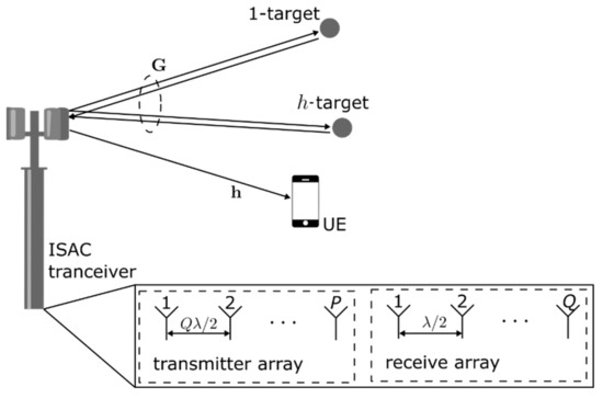
Figure 1.
MIMO-OFDM monostatic ISAC scenario.
The BS transmitted signal carries data information to a user equipment (UE) within its coverage area, which is equipped with a single antenna element. At the same time, the transmitted signal is scattered back from objects within the coverage area. The MIMO-OFDM ISAC BS receives the echoes and detects the presence of objects. The vector and the matrix represents the communication and radar channel, respectively. For communication processing, it is assumed that the channel is known at the communication terminal. For radar processing, the transmitted signal is assumed to be known at the radar receiver. In the following sections the ISAC transmitter, receiver and communication terminal are described.
2.1. ISAC Transmitter
The ISAC transmitter, the BS, is equipped with transmitting antennas and receiving antennas. The transmitter antenna elements are spaced by a distance , where denotes the wavelength. The specific spacing of the transmitting antennas was selected such that it obeys the virtual array concept [12], which enhances direction-finding resolution. Besides, OFDM and orthogonal SFBC are considered, increasing the diversity order for the communications functionality and bringing the required orthogonality between the transmitted probing signals for MIMO radar processing.
Figure 2 presents the general block diagram of the ISAC transmitter. First the binary data stream is modulated and mapped from a digital constellation alphabet (e.g., QPSK, 16-QAM) into a sequence of symbols and divided into data streams according to the SFBC scheme. Let denote the -th stream data symbol at subcarrier and OFDM symbol , then corresponding data vector for subcarrier and symbol is . The SFBC scheme is defined by the matrix , which encodes the data vector , being the selected code (e.g., Alamouti, Tarokh), and the number of frequency resources. The coding is then performed through the use of the respective coding matrix , where is the block subcarrier index and the OFDM symbol index. Then, for each antenna, the OFDM framing and cyclic prefix (CP) adding operations follow, as described in Figure 2.
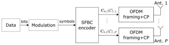
Figure 2.
Block diagram of an ISAC transmitter.
2.2. Communication Terminal
This section describes in detail the signal model and the operations performed at the communication terminal for data detection.
2.2.1. Signal Model
Consider a communication device within the coverage area of the ISAC transmitter, which is equipped with a single antenna. We aim to recover the original data sent from the ISAC system. Figure 3 illustrates the block diagram of the communication terminal considered. Namely, the communication receiver includes the inverse operations of the transmitter. First the CP is removed then the OFDM signal is deframed, decoded and demodulated. At the output follows the data estimate.
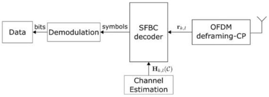
Figure 3.
Block diagram of ISAC communication receiver.
Assuming that the coherence bandwidth of the channel is higher than the duration of adjacent sub-carriers, then the received signal model at the UE for the k-th frequency block and l-th OFDM symbol, after CP removal and FFT, can be expressed [22] as
where, is the channel frequency response between the transmitting antennas and the single receiving antenna and denotes white Gaussian noise.
2.2.2. Data Detection
The soft decision of subcarrier and OFDM symbol data vector is obtained by performing the operation,
where denotes the equivalent channel considering SFBC code was used at the transmitter and represents the equivalent received signal, whose structure depends on the SFBC scheme, as follows
Substituting (3) into (2), the next relation is obtained, where is easy to see that the ISI is completely removed.
The equality (3) follows from the equality . Section 3 provides detailed structures through examples.
2.3. RADAR Terminal
This section starts by describing the receiver main blocks and signal model, then follows the description of the channel model and finally the method to estimate the target parameters.
2.3.1. Signal Model
The radar receiver is co-located with the ISAC transmitter, i.e., monostatic radar topology. Figure 4 shows a schematic of the receiver in the MIMO-ISAC transceiver. The receiver ULA in Figure 4 is equipped with antenna elements spaced by a distance of , which enables the virtual array concept [12]. The objective of the radar receiver is to perform estimation of target parameters.
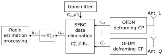
Figure 4.
Co-located receiver schematic in MIMO-ISAC transceiver.
After CP removal and OFDM deframing, the received signal model at the q-th receiving antenna, for sub-carrier and block , is given [22] by
where denotes the channel frequency response between the transmitting antennas and the q-th antenna element of the receiver ULA and denotes white Gaussian noise.
Let us define , and as the concatenation of all receiving antennas signals, then from (5) follows
2.3.2. Channel Model
Considering that the transmitted signal is reflected by targets the frequency domain response of the channel is described [2] by
where denotes the Doppler frequency, the delay, the electrical angle, the OFDM symbol duration, the subcarrier spacing and the speed of light. and denote the transmitter and receiver array response vectors.
Let us define the vector , where the operator vectorizes the input matrix column by column, then from (7) follows that
where is the array response vector of the virtual array formed by the transmitter and receiver ULA. As for the th antenna element of the virtual array , the th element of the vectorized channel is given by
2.3.3. Target Parameter Estimation
The objective is now to recover the channel matrix by making use of the Hermitian property of the coding matrix , true for orthogonal SFBCs. The channel may be estimated as
where the last equality follows from . Therefore, from follows where entry is . The channel response is identical to the channel response of a system with one transmitting antenna and a uniform linear array with receiving antennas with an inter-antenna distance of . This -element array is the virtual antenna array [12], which is obtained with just physical antenna elements.
Accordingly to (9) the target parameters may be estimated by performing an DFT or IDFT along the three dimensions of [17]. The IDFT performed along the dimension provides an estimative of the range, the DFT along the dimension an estimative of the velocity and the IDFT along the dimension provides an estimative of the electrical angle (target angle). For instance, for obtaining the delay-Doppler radar image, a well-known tool for resolving sinusoids, based on DFT and IDFT, known as the two-dimensional complex periodogram [17] can be used,
where the pair stands as a bin of the periodogram, with and . A sinusoid in results in a peak in , which corresponds to the range-velocity bin of the target. Similar processing to (11) yields the angle–velocity or range–angle radar images [17].
3. SFBC Practical Examples
In the previous section the proposed method was described considering a generic SFBC. In the following, the approach is detailed for specific SFBCs, namely Alamouti and Tarokh codes. As the approach is quite similar for both SFBCs, only the key aspects regarding each code are presented.
3.1. SFBC Alamouti
Following the Alamouti approach, after the modulation stage, the symbols are separated in two data streams and . The data streams are then coded into a two frequency-slot block described by the presented matrix
where column 1 (2) of matrix corresponds to the signal to be transmitted on antenna 1 (2), and decoded using the Hermitian of the equivalent channel matrix defined by
3.2. SFBC Tarokh
In the Tarokh approach after the modulation stage, the symbols are separated in four data streams , , and . These data streams are then coded in an eight frequency-slot block described by the presented matrix . As an example, let us consider a Tarokh code with antennas and frequency resources, with a code rate of .
4. System Performance
In this section, the performance of the proposed ISAC system is presented and evaluated for all the previously mentioned approaches. Results are presented both for the communication and radar functionalities, first considering the use of Alamouti and then Tarokh SFBCs. Namely for the communication the metric under consideration is the bit-error-rate (BER) and for the radar the corresponding radar images are presented. Finally, the results obtained for the two codes are compared and final conclusions drawn.
4.1. ISAC Specifications and Scenarios Description
As pointed out, the channel can be modeled as a sparse mmWave channel made-up of H paths, as in (7), from which it is desired to estimate the parameters of the paths, i.e., range, velocity and angle-of-arrival (AoA). Therefore, to validate SFBC for radio-sensing applications, first the two-dimensional range-velocity/AoA-velocity radar imaging obtained for several targets are presented. Then, analysis of the resolution of the AoA is given for several SFBC and receiving antennas. Finally, the BER performance for several SFBCs and modulation schemes is presented.
The MIMO OFDM ISAC system operates at = 24 GHz ISM mmWave band, which has been used for research purposes as it is deregulated. The range–velocity bin is estimated through a complex periodogram [17] over the OFDM frame. Therefore, the OFDM parameters are chosen to fulfil a set of design criteria as, maximum unambiguous range , maximum unambiguous velocity , range resolution and velocity resolution . The design criteria and OFDM parameters are summarized in Table 1.

Table 1.
OFDM and design criteria parameters for ISAC system.
4.2. Results for Alamouti and Tarokh
First, for validating the SFBC for radio-sensing applications, we consider an ISAC scenario with two transmitting antennas (Alamouti SFBC, P = 2), eight receiving antennas (Q = 8), and eight targets (H = 8), from which the range, velocity and AoA parameters are summarized in Table 2.
Table 2.
Target parameters.
Figure 5 illustrates the normalized range–velocity and AoA-velocity AF obtained for targets in Table 2. At a glance, it can be seen that signals resulting from Alamouti SFBC can be exploited for radio-sensing applications.

For the analysis of AoA estimation, Alamouti and Tarokh SFBC and different ULA configurations of the receptor are considered. Figure 6 shows a scenario with two targets with a velocity and AoA equal to (12.4914 m/s, 0°) and (24.9827 m/s, 65°), respectively. Results are obtained for the Alamouti and Tarokh codes considering 2 and 4 transmitting antennas, respectively. For the receiver both an ULA with 8 and 32 antennas are considered.

Figure 6.
Normalized 2D AoA-velocity AF obtained for two targets with a (velocity, AoA) equal to (12.4914 m/s, 0°) and (24.9827 m/s, 65°) for scenarios: (a) Alamouti SFBC and receiver ULA with 8 antenna elements; (b) Alamouti SFBC and receiver ULA with 32 antenna elements; (c) Tarokh SFBC and receiver ULA with 8 antenna elements and (d) Tarokh SFBC and receiver ULA with 32 antenna elements.
From Figure 6, it can be noticed that when the angle approaches 90 degrees (e.g., target at 65°), the resolution attained degrades when compared to the target located at 0°, this effect is more evident in Figure 5a, where the resolution is distorted from 65°. Additionally, for both Alamouti and Tarokh scenarios, the direction-finding resolution improves when the number of receiver antennas increases. A comparison of the direction-finding resolution between SFBC and the interleaved waveform approach in [14,20] is presented in Figure 7.
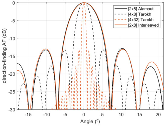
Figure 7.
Direction-finding resolution comparison between SFBCs schemes and interleaved approach for a target located at 0°.
From Figure 7, it can be noticed that Alamouti SFBC with eight physical receiving antennas and the interleaved approach presents a similar direction-finding resolution. Additionally, they show less resolution than Tarokh SFBC with eight physical receiving antennas. This is a direct consequence of the PQ virtual array configuration. Although Tarokh SFBC presents better direction-finding resolution, it requires eight frequency resources; this is Nr = 8, and therefore the unambiguous range reduces to 1.64 μs, which is less than the maximum unambiguous range of 2 μs chosen by design. This implies that by implementing Tarokh, targets located between 246 and 300 m cannot be estimated. Finally, Figure 8 illustrates a BER comparison between the SFBCs schemes and the interleaved approach [14,20].
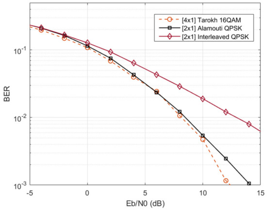
Figure 8.
BER performance comparison.
Figure 8 shows that as in legacy wireless communication systems, the use of orthogonal SFBCs bring an improvement in the BER, i.e., the 2 × 1 Alamouti QPSK reports better BER than the 2 × 1 interleaved QPSK scheme. Additionally, the MISO-OFDM Tarokh 16-QAM and Alamouti QPSK report a similar BER. However, Alamouti outperforms Tarokh regarding efficiency, since it has a rate of one, while Tarokh has a rate of a half, i.e., Tarokh use twice the bandwidth as Alamouti for transmitting the same data. SFBC is therefore a promising candidate for the integration of radar and communications. The structure of the SFBC signals allows the formation of virtual arrays, achieving the same performance of interleaved orthogonal signaling, while enabling diversity in the communication domain, a feature that does not occur with orthogonal inter-leaving.
5. Conclusions
In this work, we have proposed the use of SFBC for the integration of radar and communication functionalities. The SFBC orthogonality properties provide the orthogonality necessary for MIMO radar to multiplex the different antenna signals and at the same time enhance the diversity order achieved by the communication functionality. These allow the radar resolution to be improved significantly by resorting to the virtual array concept, and the added diversity significantly reduces the resulting BER. The use of different SFBCs allows a tradeoff to be made between the achieved communication and radar performance. For example, the Alamouti code, applicable for the case with two transmitting antennas duplicates the radar spatial resolution and achieves diversity order 2. On the other hand, the Tarokh code, applicable for the case with four transmitting antennas, improves the radar spatial resolution by a factor of four, together with the diversity, but the code rate is reduced by half. Additionally, we compared the performance between SFBC schemes and the interleaved approach in terms of direction-finding resolution and BER. It was shown that for the same virtual array size, SFBC and interleaved report similar resolution. However, for the communication with interleaved, we lose the diversity benefit, and we have worse BER. Therefore, for the objectives of joint radar and communication, the use of SFBC is the preferred solution. Due to its low complexity, good performance, and reduced integration requirements, the method is promising for future ISAC systems.
Author Contributions
D.C. and A.S. supported the main idea. A.G., A.S. and D.C. contributed to the methodology. D.C., S.C. and L.L. described the system model and wrote the manuscript. L.L. and S.C. designed the scenarios for proof of concept and carried out the simulations and analysis of results. A.S., A.G. and D.C. supervised the work, while L.L, D.C., S.C. and A.S. reviewed and edited the manuscript. All authors have read and agreed to the published version of the manuscript.
Funding
This work has received funding from the European Union’s Horizon 2020 research and innovation programme under the Marie Skłodowska-Curie ETN TeamUp5G, grant agreement No. 813391 and UIDB/50008/2020-UIDP/50008/2020 project.
Institutional Review Board Statement
Not applicable.
Informed Consent Statement
Not applicable.
Data Availability Statement
Not applicable
Conflicts of Interest
The authors declare no conflict of interest.
References
- Giordani, M.; Polese, M.; Mezzavilla, M.; Rangan, S.; Zorzi, M. Toward 6G networks: Use cases and technologies. IEEE Commun. Mag. 2020, 58, 55–61. [Google Scholar] [CrossRef]
- Liu, F.; Masouros, C.; Petropulu, A.P.; Griffiths, H.; Hanzo, L. Joint radar and communication design: Applications, state-of-the-art, and the road ahead. IEEE Trans. Commun. 2020, 68, 3834–3862. [Google Scholar] [CrossRef] [Green Version]
- Leyva, L.; Castanheira, D.; Silva, A.; Gameiro, A.; Hanzo, L. Cooperative multiterminal radar and communication: A new paradigm for 6G mobile networks. IEEE Veh. Technol. Mag. 2021, 16, 38–47. [Google Scholar] [CrossRef]
- Gameiro, A.; Castanheira, D.; Sanson, J.; Monteiro, P.P. Research challenges, trends and applications for future joint radar communications systems. Wirel. Pers. Commun. 2018, 100, 81–96. [Google Scholar] [CrossRef]
- Paul, B.; Chiriyath, A.R.; Bliss, D.W. Survey of rf communications and sensing convergence research. IEEE Access 2017, 5, 252–270. [Google Scholar] [CrossRef]
- Zheng, L.; Lops, M.; Eldar, Y.C.; Wang, X. Radar and Communication Coexistence: An Overview: A Review of Recent Methods. IEEE Signal Process. Mag. 2019, 36, 85–99. [Google Scholar] [CrossRef]
- Zhang, A.; Rahman, L.; Huang, X.; Guo, Y.J.; Chen, S.; Heath, R.W. Perceptive mobile network: Cellular networks with radio vision via joint communication and radar sensing. IEEE Veh. Technol. Mag. 2021, 16, 20–30. [Google Scholar] [CrossRef]
- Zheng, L.; Tse, D.N. Diversity and multiplexing: A fundamental tradeoff in multiple-antenna channels. IEEE Trans. Inf. Theory 2003, 49, 1073–1096. [Google Scholar] [CrossRef] [Green Version]
- Fishler, E.; Haimovich, A.; Blum, R.S.; Chizhik, D.; Cimini, L.; Valenzuela, R. MIMO radar: An idea whose time has come. In Proceedings of the 2004 IEEE Radar Conference, Philadelphia, PA, USA, 29 April 2004; pp. 71–78. [Google Scholar] [CrossRef] [Green Version]
- Roberts, W.; Stoica, P.; Li, J.; Yardibi, T.; Sadjadi, F.A. Iterative Adaptive Approaches to MIMO Radar Imaging. IEEE J. Sel. Top. Signal Process. 2010, 4, 5–20. [Google Scholar] [CrossRef]
- Liu, F.; Masouros, C.; Li, A.; Sun, H.; Hanzo, L. MU-MIMO Communications with MIMO Radar: From Co-Existence to Joint Transmission. IEEE Trans. Wirel. Commun. 2018, 17, 2755–2770. [Google Scholar] [CrossRef]
- Li, J.; Stoica, P. MIMO Radar with Colocated Antennas. IEEE Signal Process. Mag. 2007, 5, 106–114. [Google Scholar] [CrossRef]
- Imani, S.; Nayebi, M.M.; Ghorashi, S.A. Transmit Signal Design in Colocated MIMO Radar without Covariance Matrix Optimization. IEEE Trans. Aerosp. Electron. Syst. 2017, 53, 2178–2186. [Google Scholar] [CrossRef]
- Sanson, J.B.; Castanheira, D.; Gameiro, A.; Monteiro, P.P. Cooperative Method for Distributed Target Tracking for OFDM Radar with Fusion of Radar and Communication Information. IEEE Sens. J. 2021, 21, 15584–15597. [Google Scholar] [CrossRef]
- Sadeque, A.; Ali, T.; Saquib, M.; Ali, M. Waveform Transmission Scheme for MIMO Radar Imaging Based on Space-Time Block Codes. IEEE Trans. Aerosp. Electron. Syst. 2014, 50, 777–785. [Google Scholar] [CrossRef]
- Bao, D.; Qin, G.; Dong, Y.-Y. A Superimposed Pilot-Based Integrated Radar and Communication System. IEEE Access 2020, 8, 11520–11533. [Google Scholar] [CrossRef]
- Sturm, C.; Wiesbeck, W. Waveform Design and Signal Processing Aspects for Fusion of Wireless Communications and Radar Sensing. Proc. IEEE 2011, 99, 1236–1259. [Google Scholar] [CrossRef]
- Sit, Y.L.; Sturm, C.; Baier, J.; Zwick, T. Direction of arrival estimation using the MUSIC algorithm for a MIMO OFDM radar. In Proceedings of the 2012 IEEE Radar Conference, Atlanta, GA, USA, 7–11 May 2012; pp. 226–229. [Google Scholar] [CrossRef]
- Barneto, C.B.; Riihonen, T.; Turunen, M.; Anttila, L.; Fleischer, M.; Stadius, K.; Ryynanen, J.; Valkama, M. Full-Duplex OFDM Radar with LTE and 5G NR Waveforms: Challenges, Solutions, and Measurements. Trans. Microw. Theory Tech. 2019, 67, 4042–4054. [Google Scholar] [CrossRef] [Green Version]
- Sit, Y.L.; Nuss, B.; Zwick, T. On Mutual Interference Cancellation in a MIMO OFDM Multiuser Radar-Communication Network. IEEE Trans. Veh. Technol. 2018, 67, 3339–3348. [Google Scholar] [CrossRef]
- Sanson, J.B.; Tome, P.M.; Castanheira, D.; Gameiro, A.; Monteiro, P.P. High-Resolution Delay-Doppler Estimation Using Received Communication Signals for OFDM Radar-Communication System. IEEE Trans. Veh. Technol. 2020, 69, 13112–13123. [Google Scholar] [CrossRef]
- Leyva, L.; Maciel, J.; Castanheira, D.; Silva, A.; Gameiro, A. Alamouti coding scheme and virtual array concept for joint radar and communication systems. In Proceedings of the 2020 12th International Symposium on Communication Systems, Networks and Digital Signal Processing (CSNDSP), Porto, Portugal, 20–22 July 2020; pp. 1–5. [Google Scholar] [CrossRef]
Publisher’s Note: MDPI stays neutral with regard to jurisdictional claims in published maps and institutional affiliations. |
© 2022 by the authors. Licensee MDPI, Basel, Switzerland. This article is an open access article distributed under the terms and conditions of the Creative Commons Attribution (CC BY) license (https://creativecommons.org/licenses/by/4.0/).