
A Smart Multi-Sensor Device to Detect Distress in Swimmers

 , ,
, , 
Abstract
1. Introduction
Related Works
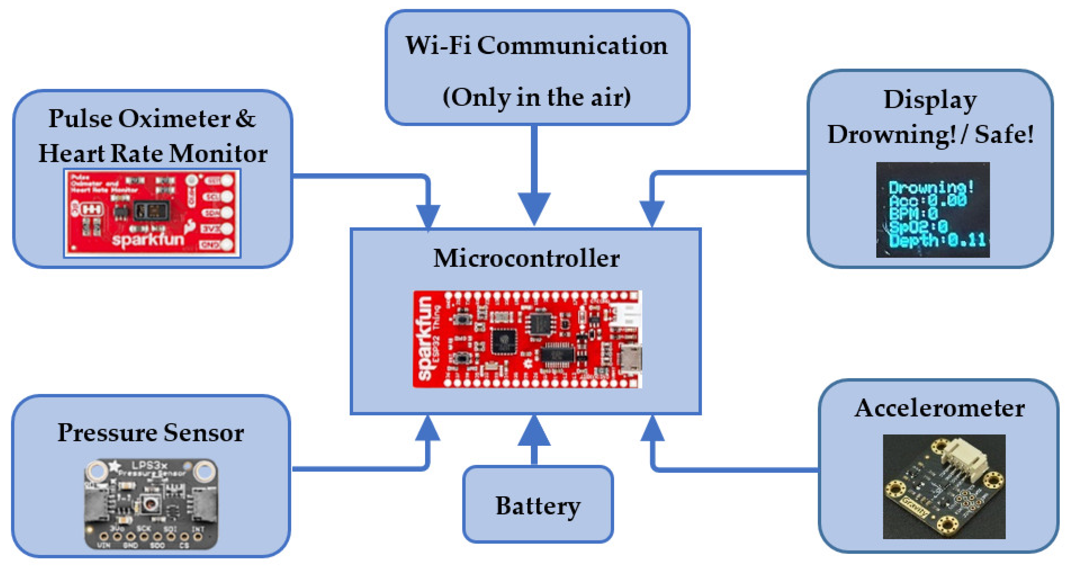
2. System Design
2.1. Measurable Parameters
2.1.1. Heart Rate
2.1.2. Blood Oxygen Saturation
2.1.3. Movement Pattern Recognition
2.1.4. Water Depth
2.1.5. Duration of Submersion
2.2. Sensing Elements
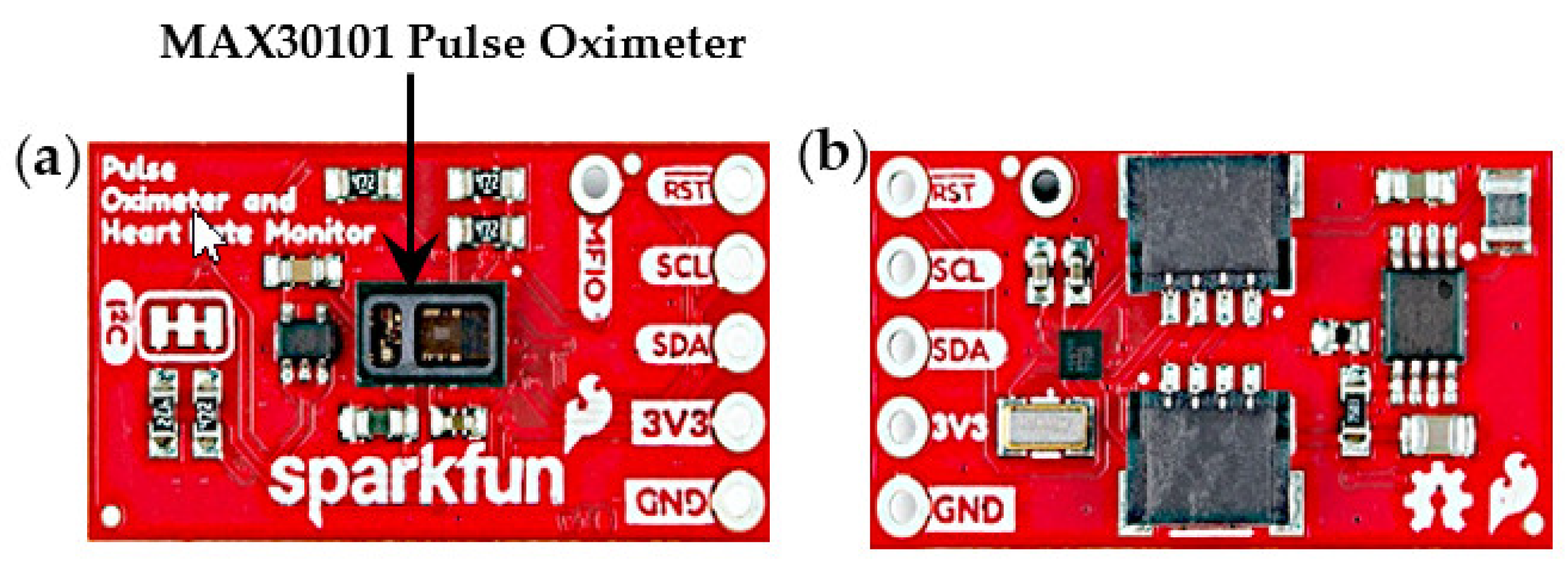
2.2.1. Pulse Oximetry
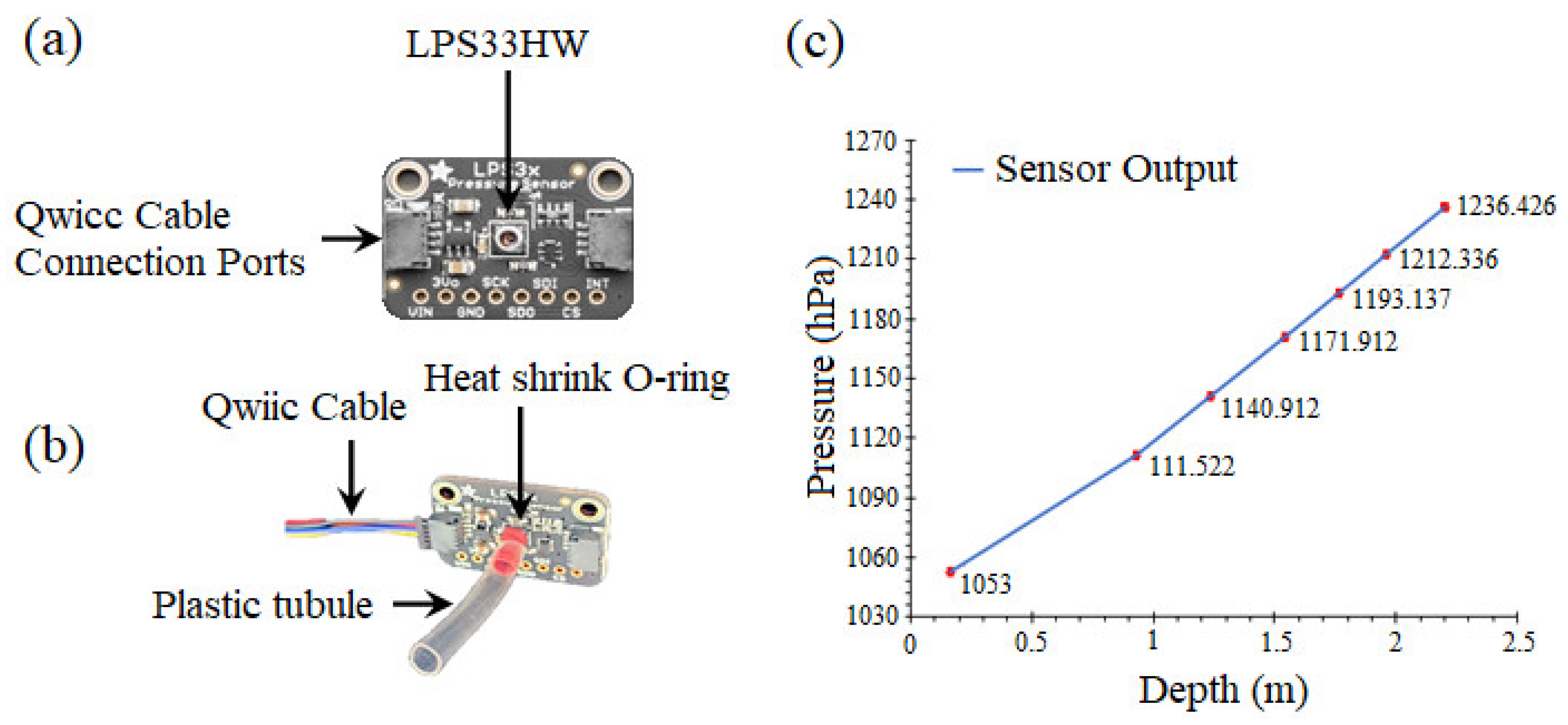
2.2.2. Pressure Sensor
2.2.3. Microcontroller
2.2.4. Battery
2.2.5. OLED Display
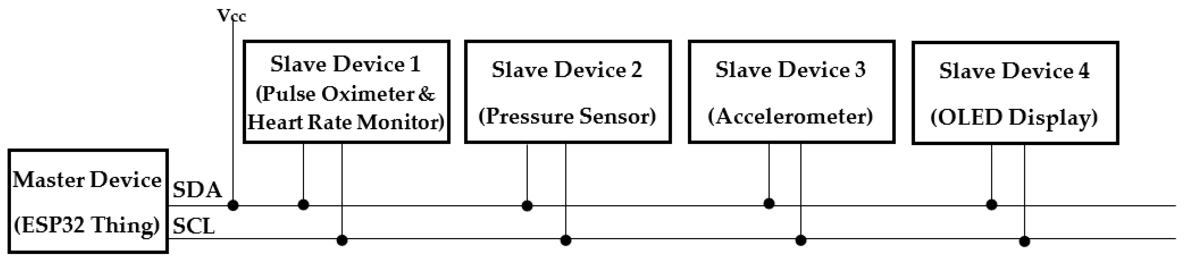
2.2.6. Connections and Communication Protocols
2.2.7. Power Usage and Range
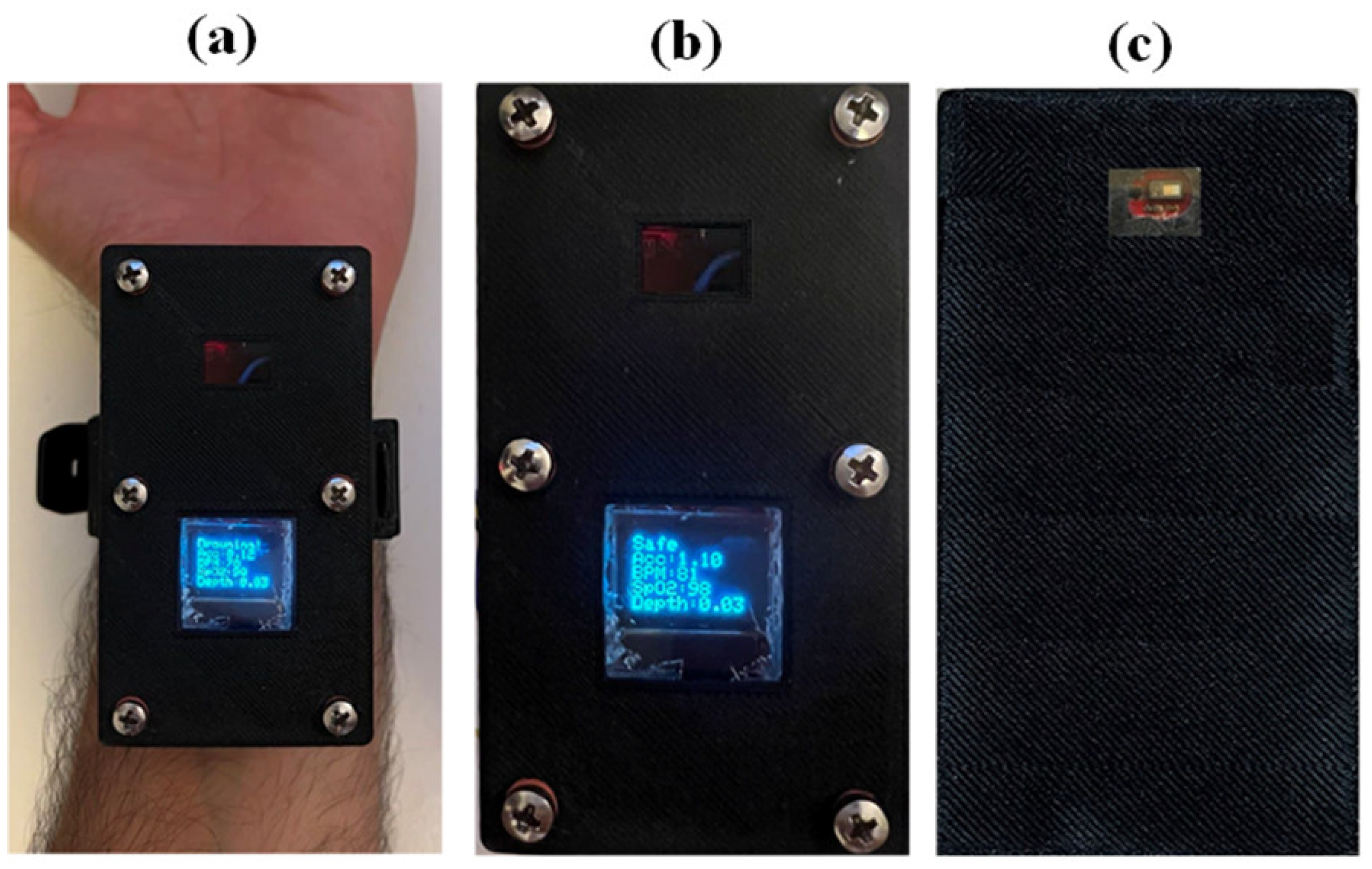
3. Hardware Integration of the System
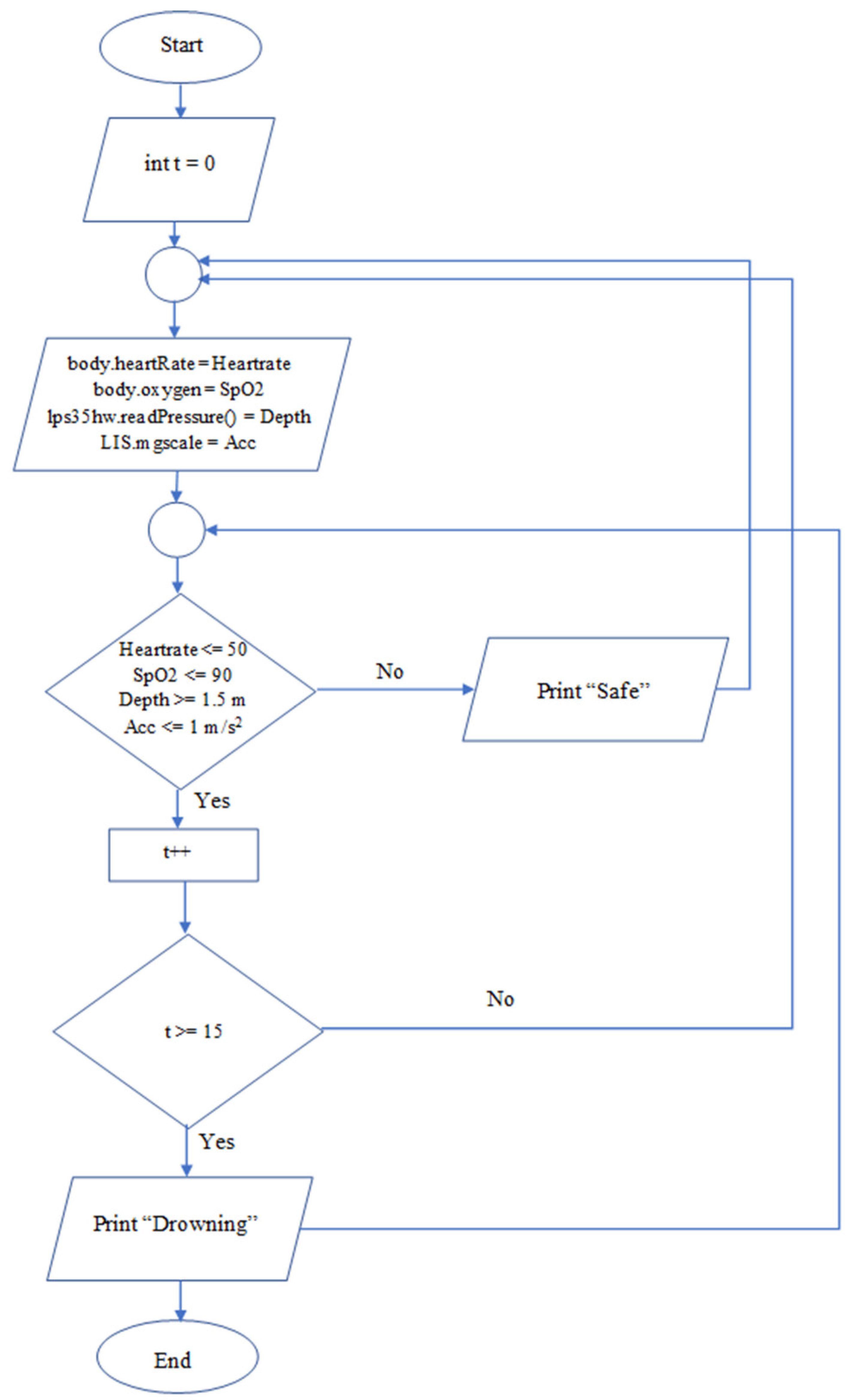
4. Working Principle
5. Methodology, Results, and Discussion
5.1. Testing Sensors Individually
5.1.1. Heart Rate Test
5.1.2. Blood Oxygen Saturation
5.1.3. Water Depth
5.1.4. Swimmer Movement
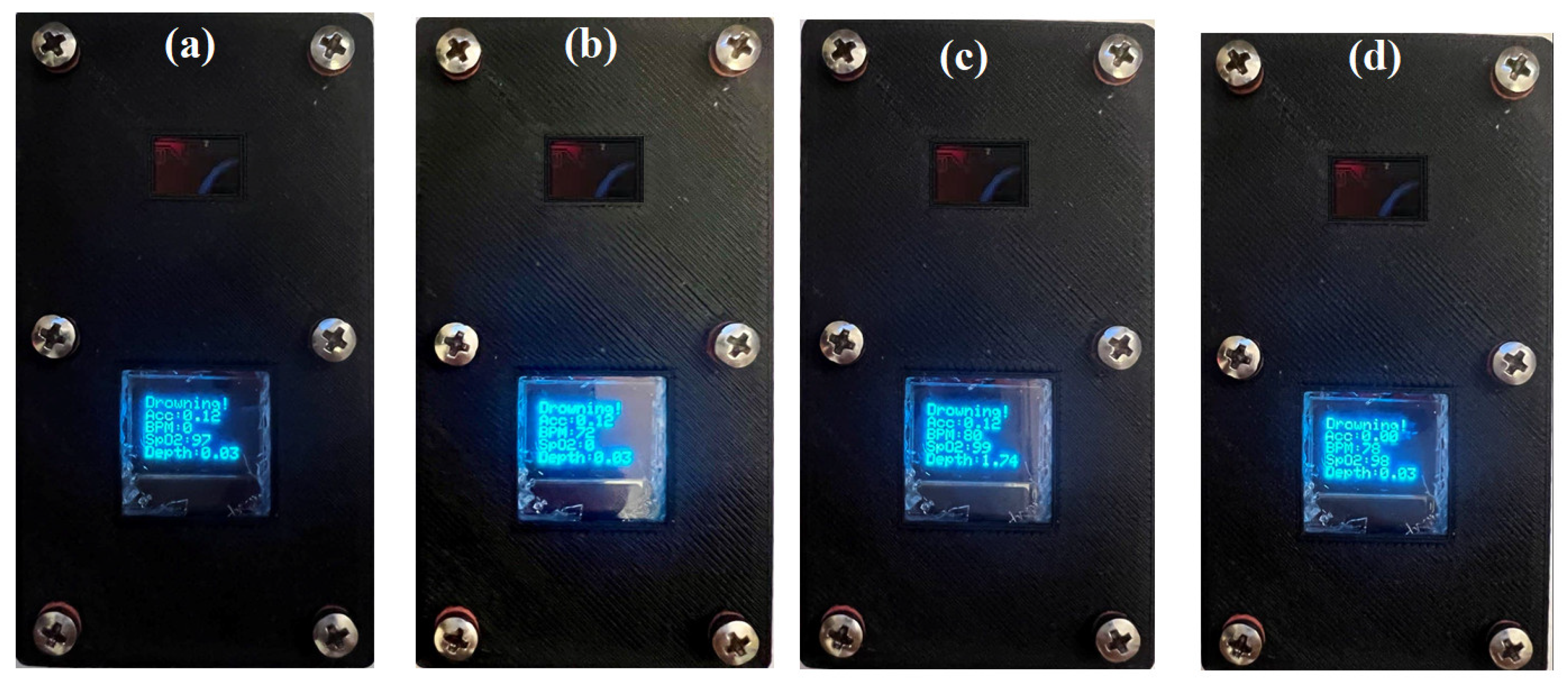
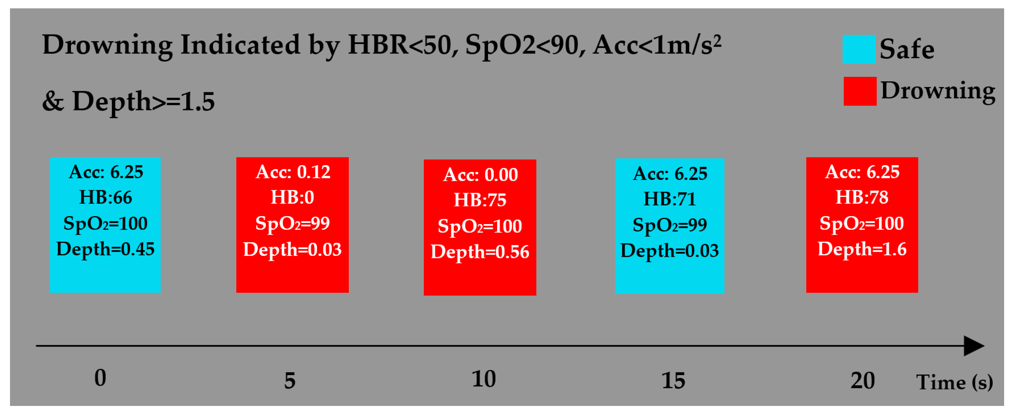
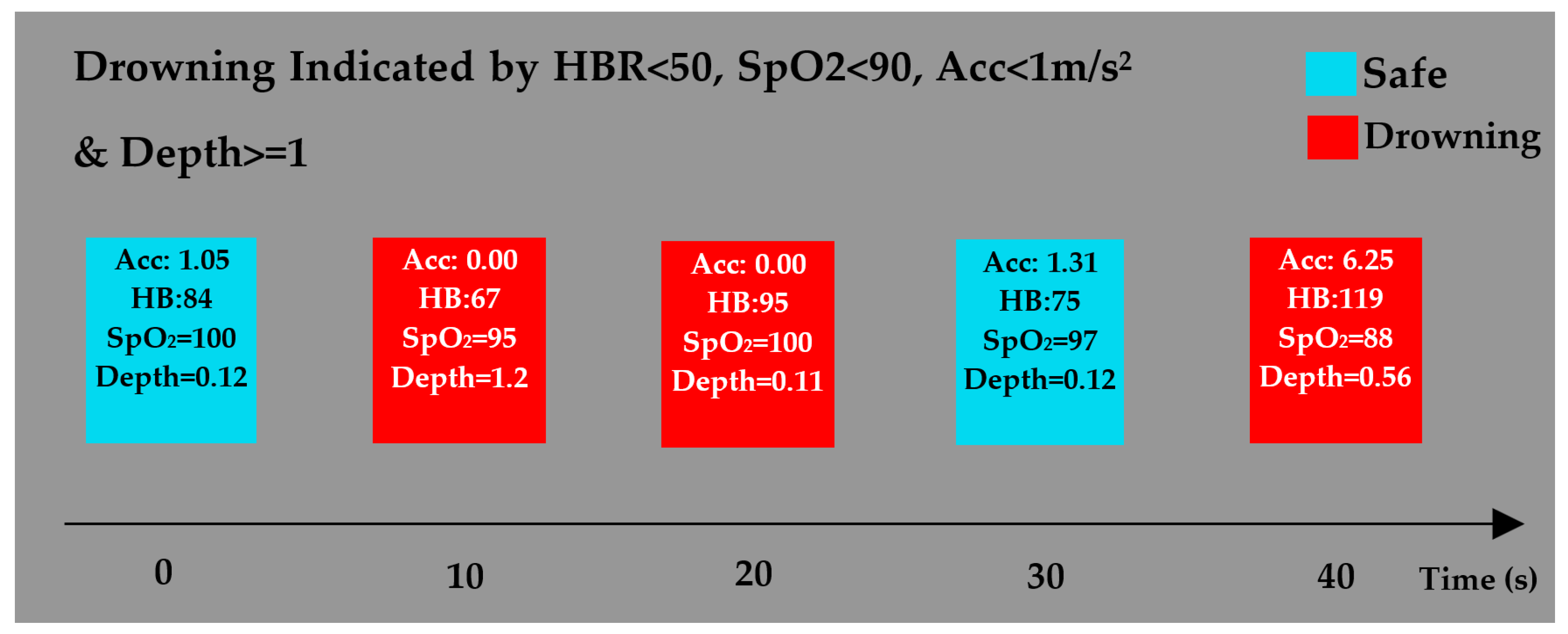
5.2. Testing the Entire System
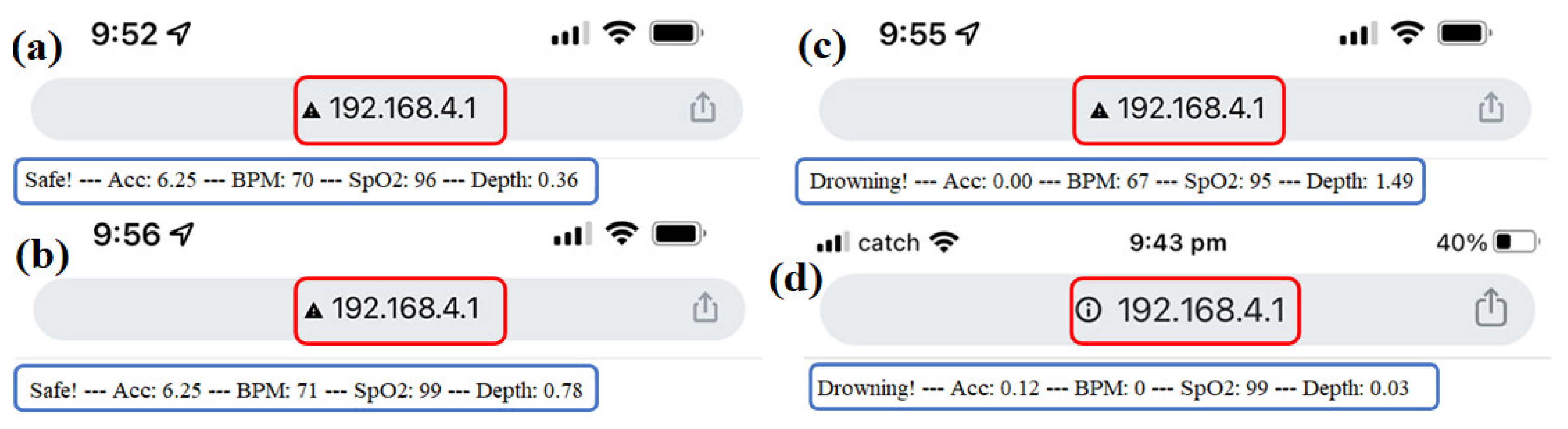
5.2.1. Air Test
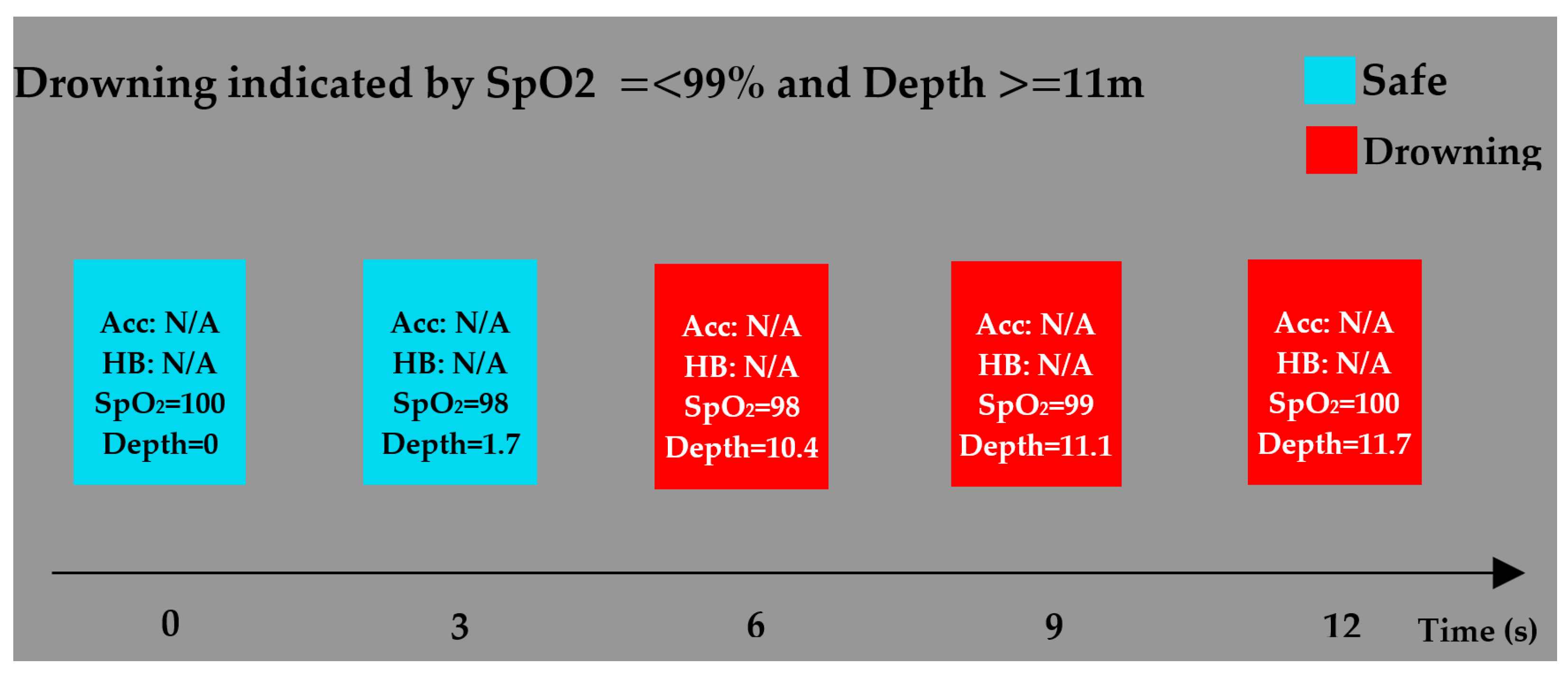
5.2.2. Underwater Test
6. Conclusions
Supplementary Materials
Author Contributions
Funding
Informed Consent Statement
Data Availability Statement
Acknowledgments
Conflicts of Interest
References
- World Health Organization. Drowning. Available online: https://www.who.int/news-room/fact-sheets/detail/drowning (accessed on 28 August 2021).
- Royal Life Saving Society. Royal life Saving National Drowning Report; Royal Life Saving Society—Australia. 2020. Available online: https://www.royallifesaving.com.au/ (accessed on 28 August 2021).
- Hamilton, K.; Keech, J.J.; Peden, A.E.; Hagger, M.S. Alcohol use, aquatic injury, and unintentional drowning: A systematic literature review. Drug Alcohol Rev. 2018, 37, 752–773. [Google Scholar] [CrossRef] [PubMed]
- Pajunen, T.; Vuori, E.; Vincenzi, F.F.; Lillsunde, P.; Smith, G.; Lunetta, P. Unintentional drowning: Role of medicinal drugs and alcohol. BMC Public Health 2017, 17, 1–10. [Google Scholar] [CrossRef] [PubMed]
- Bain, E.; Keller, A.E.; Jordan, H.; Robyn, W.; Pollanen, M.S.; Williams, A.S.; Donner, E.J. Drowning in epilepsy: A population-based case series. Epilepsy Res. 2018, 145, 123–126. [Google Scholar] [CrossRef] [PubMed]
- Denny, S.A.; Quan, L.; Gilchrist, J.; McCallin, T.; Shenoi, R.; Yusuf, S.; Hoffman, B.; Weiss, J. Prevention of drowning. Pediatrics 2019, 143, e20190850. [Google Scholar] [CrossRef] [PubMed]
- Evans, J.; Javaid, A.A.; Scarrott, E.; Bamber, A.R.; Morgan, J. Fifteen-minute consultation: Drowning in children. Arch. Dis. Child.-Educ. Pract. 2021, 106, 88–93. [Google Scholar] [CrossRef] [PubMed]
- Shehata, A.M.; Mohamed, E.M.; Salem, K.L.; Mohamed, A.M.; Salam, M.A.; Gamil, M.M. A Survey of Drowning Detection Techniques. In Proceedings of the 2021 International Mobile, Intelligent, and Ubiquitous Computing Conference (MIUCC), Cairo, Egypt, 26–27 May 2021; pp. 286–290. [Google Scholar]
- Chaudhari, T.K.Y.; Pandit, G.; Gupta, P.; Kumar, M. Anti Drowning system using remote control. IOSR J. Eng. 2016, 1, 38–42. [Google Scholar]
- John, S.N.; Ukpabio, I.G.; Omoruyi, O.; Onyiagha, G.; Noma-Osaghae, E.; Okokpujie, K.O. Design of a drowning rescue alert system. Int. J. Mech. Eng. Technol. (IJMET) 2019, 10, 1987–1995. [Google Scholar]
- Asadnia, M.; Kottapalli, A.; Miao, J.; Randles, A.; Sabbagh, A.; Kropelnicki, P.; Tsai, J. High temperature characterization of PZT (0.52/0.48) thin-film pressure sensors. J. Micromech. Microeng. 2013, 24, 015017. [Google Scholar] [CrossRef]
- Asadnia, M.; Kottapalli, A.G.P.; Haghighi, R.; Cloitre, A.; Alvarado, P.V.; Miao, J.; Triantafyllou, M. MEMS sensors for assessing flow-related control of an underwater biomimetic robotic stingray. Bioinspir. Biomim. 2015, 10, 036008. [Google Scholar] [CrossRef] [PubMed]
- Dusek, J.; Kottapalli, A.; Woo, M.; Asadnia, M.; Miao, J.; Lang, J.; Triantafyllou, M. Development and testing of bio-inspired microelectromechanical pressure sensor arrays for increased situational awareness for marine vehicles. Smart Mater. Struct. 2012, 22, 014002. [Google Scholar] [CrossRef]
- Kottapalli, A.; Asadnia, M.; Miao, J.; Tan, C.; Barbastathis, G.; Triantafyllou, M. Polymer MEMS pressure sensor arrays for fish-like underwater sensing applications. Micro Nano Lett. 2012, 7, 1189–1192. [Google Scholar] [CrossRef]
- Kottapalli, A.G.P.; Asadnia, M.; Miao, J.; Triantafyllou, M. Soft polymer membrane micro-sensor arrays inspired by the mechanosensory lateral line on the blind cavefish. J. Intell. Mater. Syst. Struct. 2015, 26, 38–46. [Google Scholar] [CrossRef]
- Moshizi, S.A.; Azadi, S.; Belford, A.; Razmjou, A.; Wu, S.; Han, Z.J.; Asadnia, M. Development of an ultra-sensitive and flexible piezoresistive flow sensor using vertical graphene nanosheets. Nano-Micro Lett. 2020, 12, 109. [Google Scholar] [CrossRef]
- Rafeie, M.; Welleweerd, M.; Hassanzadeh-Barforoushi, A.; Asadnia, M.; Olthuis, W.; Ebrahimi Warkiani, M. An easily fabricated three-dimensional threaded lemniscate-shaped micromixer for a wide range of flow rates. Biomicrofluidics 2017, 11, 014108. [Google Scholar] [CrossRef]
- MS, M.R.; Ali, M.; Ali, S.; Kamaludin, M. An Early Drowning Detection System for Internet of Things (IoT) Applications. Telkomnika 2018, 16, 1870–1876. [Google Scholar] [CrossRef]
- Kulkarni, A.; Lakhani, K.; Lokhande, S. A sensor based low cost drowning detection system for human life safety. In Proceedings of the 2016 5th International Conference on Reliability, Infocom Technologies and Optimization (Trends and Future Directions)(ICRITO), Noida, India, 7–9 September 2016; pp. 301–306. [Google Scholar]
- Ramani, J.G.; Gayathri, J.; Aswanth, R.; Gunasekaran, M. Automatic prevention of drowning by inflatable wrist band system. In Proceedings of the 2019 5th International Conference on Advanced Computing & Communication Systems (ICACCS), Coimbatore, India, 15–16 March 2019; pp. 346–349. [Google Scholar]
- Girela-Lopez, E.; Beltran-Aroca, C.M.; Dye, A.; Gill, J.R. Epidemiology and autopsy findings of 500 drowning deaths. Forensic Sci. Int. 2022, 330, 111137. [Google Scholar] [CrossRef] [PubMed]
- Lunetta, P. Drowning. In Asphyxiation, Suffocation, and Neck Pressure Deaths; CRC Press: Boca Raton, FL, USA, 2020; pp. 260–284. [Google Scholar]
- Modell, J.H. Drowning. N. Engl. J. Med. 1993, 328, 253–256. [Google Scholar] [CrossRef] [PubMed]
- Banting, F.; Hall, G.; Janes, J.; Leibel, B.; Lougheed, D. Physiological studies in experimental drowning (A): Preliminary report. Can. Med. Assoc. J. 1938, 39, 226. [Google Scholar] [PubMed]
- Lund, F.K.; Torgersen, J.G.; Flaatten, H.K. Heart rate monitored hypothermia and drowning in a 48-year-old man. survival without sequelae: A case report. Cases J. 2009, 2, 1–6. [Google Scholar] [CrossRef][Green Version]
- Puspitasari, A.J.; Famella, D.; Ridwan, M.S.; Khoiri, M. Design of low-flow oxygen monitor and control system for respiration and SpO2 rates optimization. In Proceedings of the Journal of Physics: Conference Series, Yogyakarta, Indonesia, 6–7 September 2019; p. 012042. [Google Scholar]
- Hunsucker, J.; Davison, S. Analysis of rescue and drowning history from a lifeguarded waterpark environment. Int. J. Inj. Control. Saf. Promot. 2011, 18, 277–284. [Google Scholar] [CrossRef] [PubMed]
- Brianna, M. 8 Truths about Drowning and ‘Dry Drowning’ Revealed. Available online: https://www.hackensackmeridianhealth.org/HealthU/2019/07/09/8-truths-about-drowning-and-dry-drowning-revealed/ (accessed on 28 August 2021).
- Longmore, S.K.; Jalaludin, B.; Breen, P.P.; Gargiulo, G.D. Comparison of bi-wavelength and tri-wavelength photoplethysmography sensors placed on the forehead. In Proceedings of the 2019 International Conference on Electrical Engineering Research & Practice (ICEERP), Sydney, NSW, Australia, 24–28 November 2019; pp. 1–4. [Google Scholar]
- Sparkfun. Sparkfun Pulse Oximeter and Heart Rate Monitor Hookup Guide. Available online: https://learn.sparkfun.com/tutorials/sparkfun-pulse-oximeter-and-heart-rate-monitor-hookup-guide/all (accessed on 28 August 2021).
- Mohan, A.; Malshe, A.P.; Aravamudhan, S.; Bhansali, S. Piezoresistive MEMS pressure sensor and packaging for harsh oceanic environment. In Proceedings of the 2004 Proceedings, 54th Electronic Components and Technology Conference (IEEE Cat. No. 04CH37546), Las Vegas, NV, USA, 4 June 2004; pp. 948–950. [Google Scholar]


| Reference | Sensing Elements | Transmitter Circuits | Receiver Circuits | Working Principle | Attachment Area |
|---|---|---|---|---|---|
| Chaudhari et al. [9] | Heartbeat rate sensor |
|
|
| Hand or head |
| John et al. [10] | Heart rate pressure sensors |
|
|
| Wrist |
| Ramdhan et al. [18] | PPG iv types of pulse sensor |
|
|
| Head |
| Kulkarni et al. [19] |
|
|
| Arm | |
| Geetha et.al. [20] | Accelerometers |
|
|
| Wrist |
Publisher’s Note: MDPI stays neutral with regard to jurisdictional claims in published maps and institutional affiliations. |
© 2022 by the authors. Licensee MDPI, Basel, Switzerland. This article is an open access article distributed under the terms and conditions of the Creative Commons Attribution (CC BY) license (https://creativecommons.org/licenses/by/4.0/).
Share and Cite
Jalalifar, S.; Kashizadeh, A.; Mahmood, I.; Belford, A.; Drake, N.; Razmjou, A.; Asadnia, M. A Smart Multi-Sensor Device to Detect Distress in Swimmers. Sensors 2022, 22, 1059. https://doi.org/10.3390/s22031059
Jalalifar S, Kashizadeh A, Mahmood I, Belford A, Drake N, Razmjou A, Asadnia M. A Smart Multi-Sensor Device to Detect Distress in Swimmers. Sensors. 2022; 22(3):1059. https://doi.org/10.3390/s22031059
Chicago/Turabian StyleJalalifar, Salman, Afsaneh Kashizadeh, Ishmam Mahmood, Andrew Belford, Nicolle Drake, Amir Razmjou, and Mohsen Asadnia. 2022. "A Smart Multi-Sensor Device to Detect Distress in Swimmers" Sensors 22, no. 3: 1059. https://doi.org/10.3390/s22031059
APA StyleJalalifar, S., Kashizadeh, A., Mahmood, I., Belford, A., Drake, N., Razmjou, A., & Asadnia, M. (2022). A Smart Multi-Sensor Device to Detect Distress in Swimmers. Sensors, 22(3), 1059. https://doi.org/10.3390/s22031059