


Experimental Investigations into Using Motion Capture State Feedback for Real-Time Control of a Humanoid Robot


Abstract
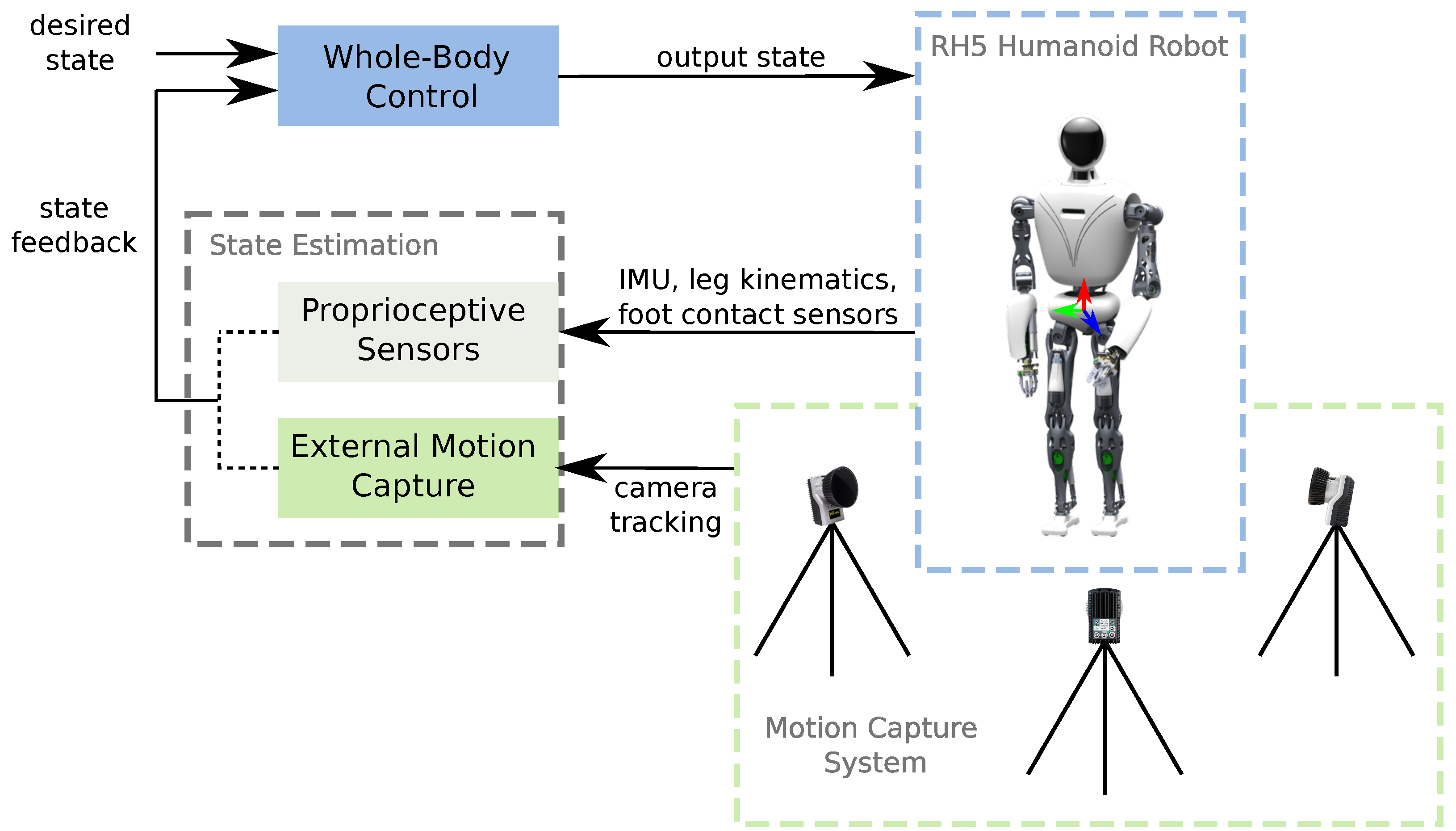
1. Introduction
2. Materials and Methods
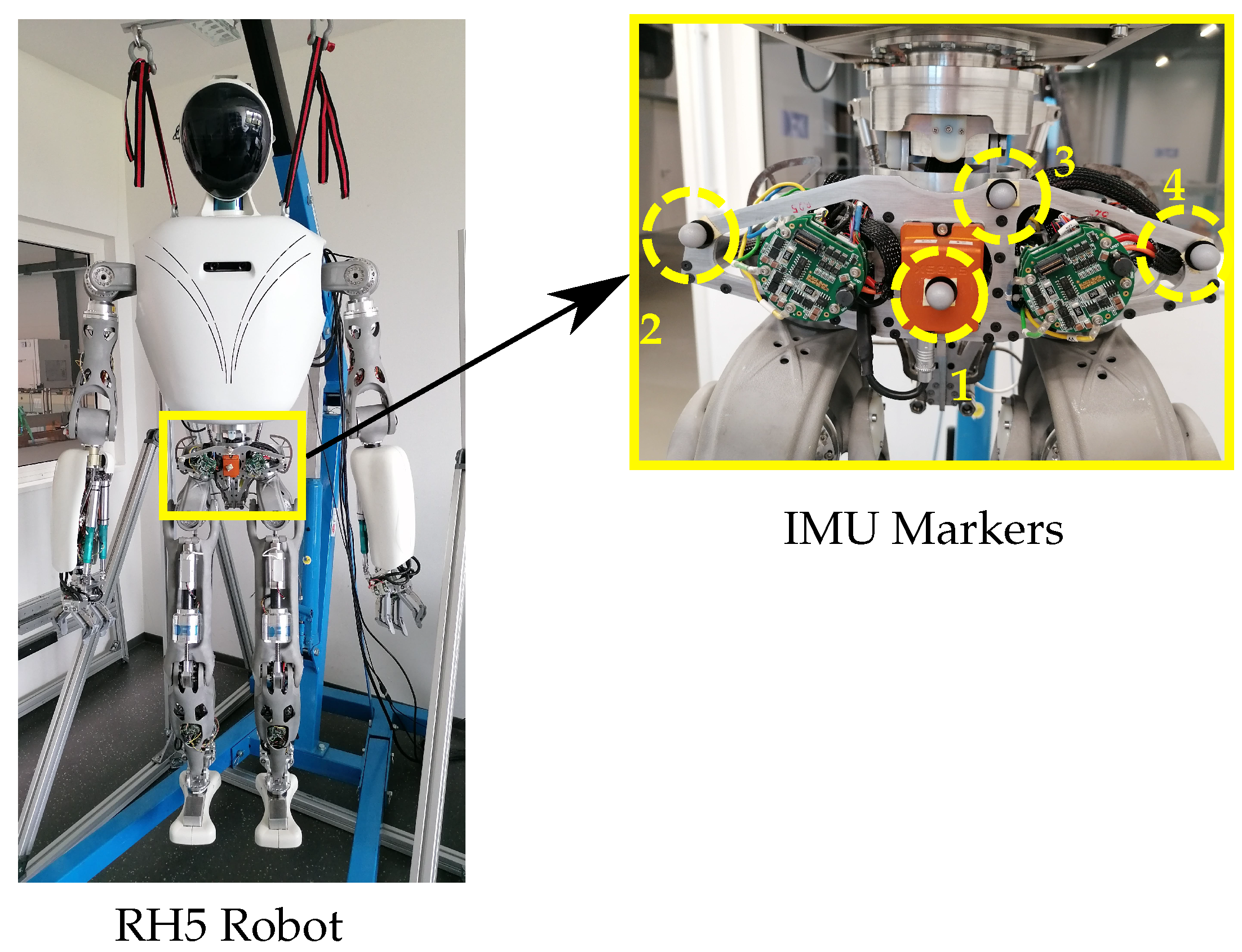
2.1. Humanoid Robot RH5
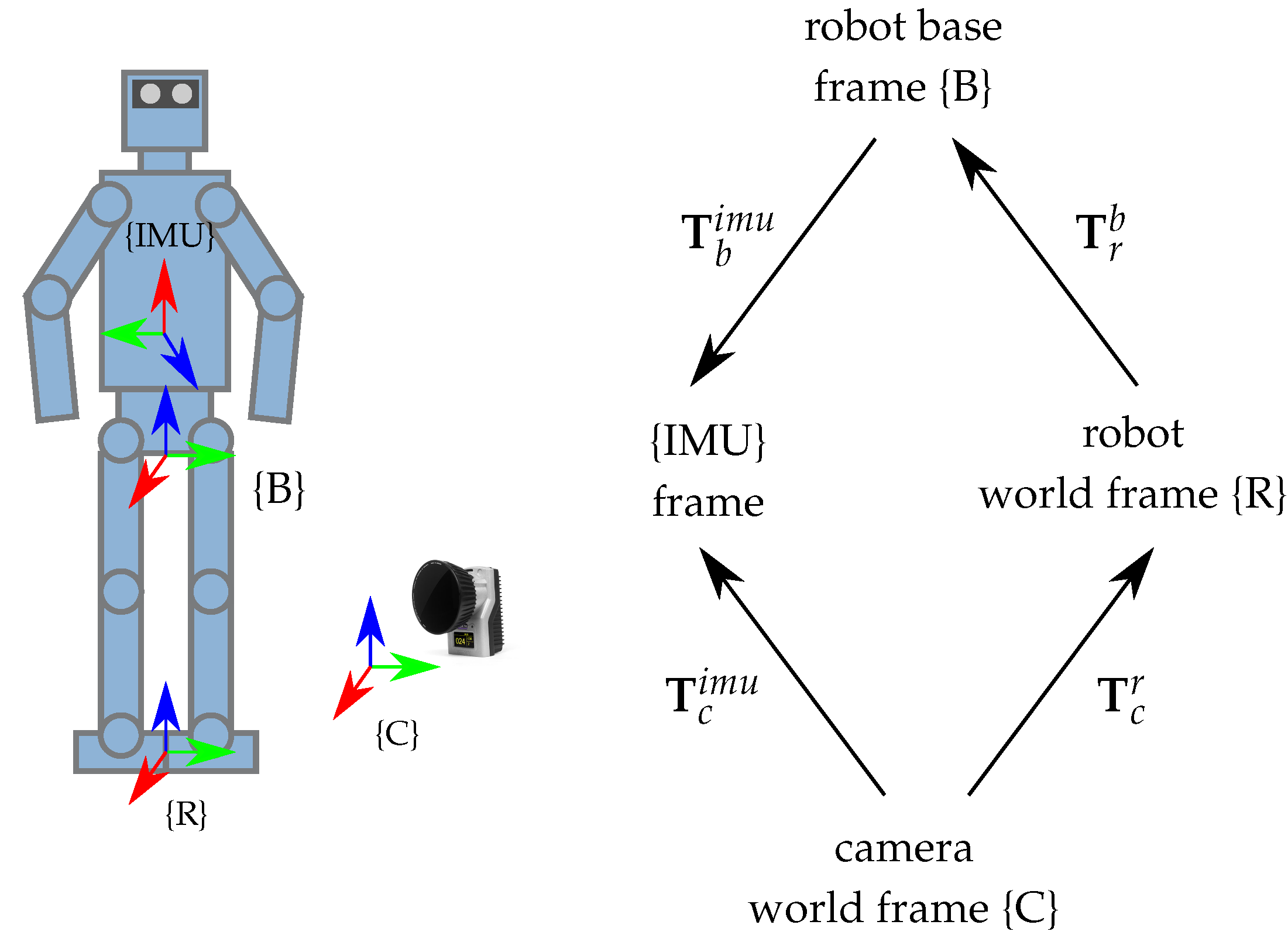
2.2. Motion Capture System
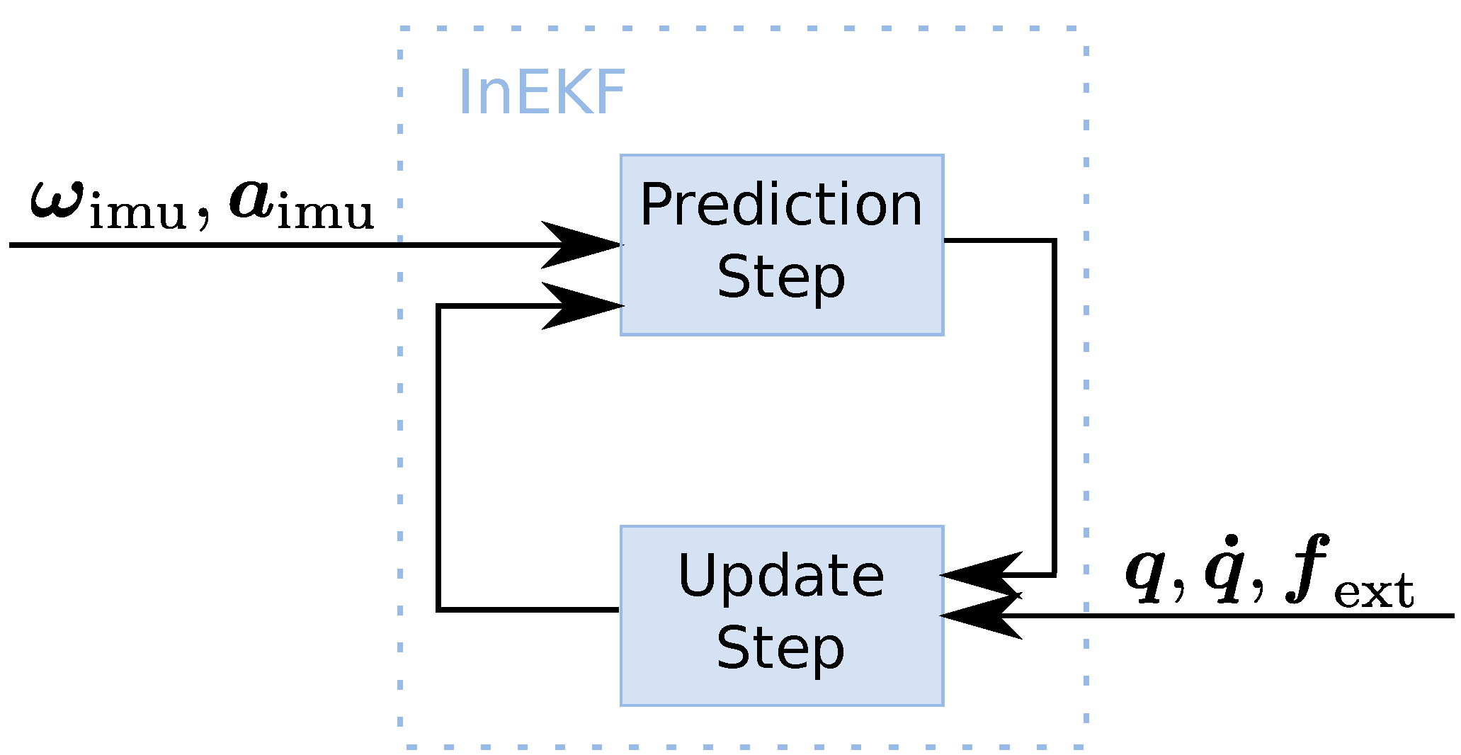
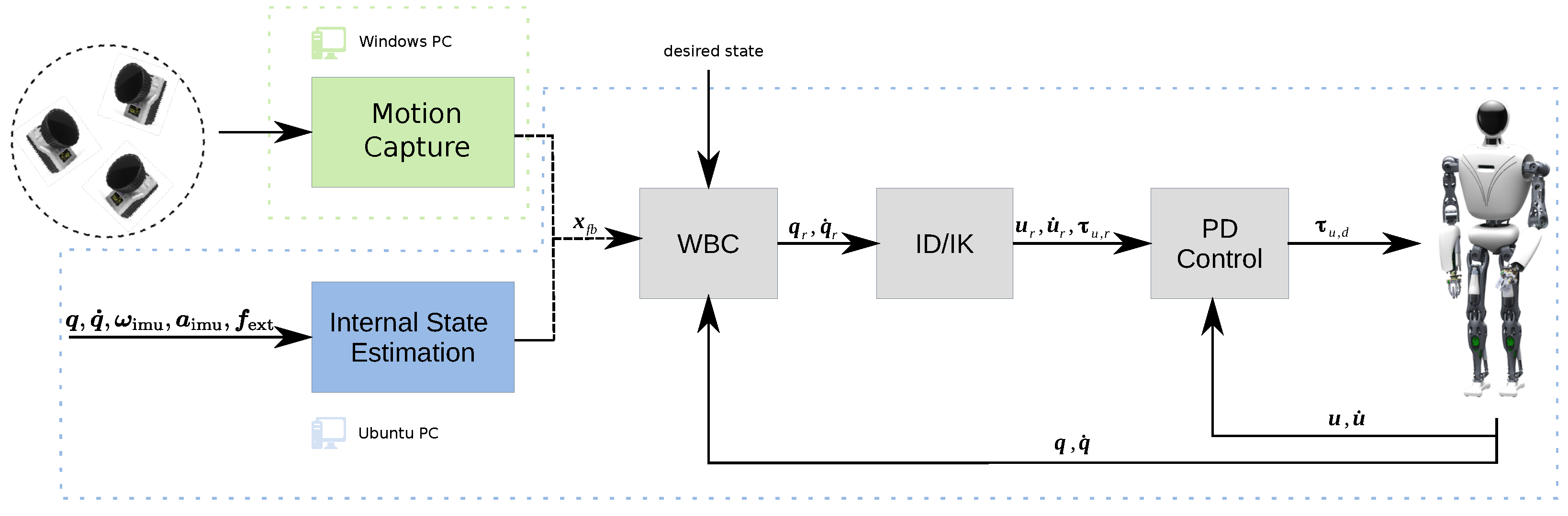
2.3. State Estimation
2.4. Whole-Body Control
3. Results
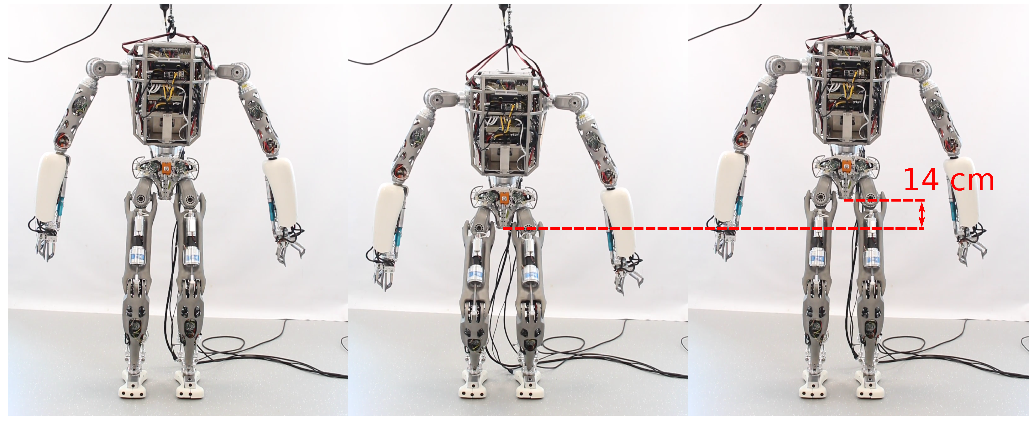
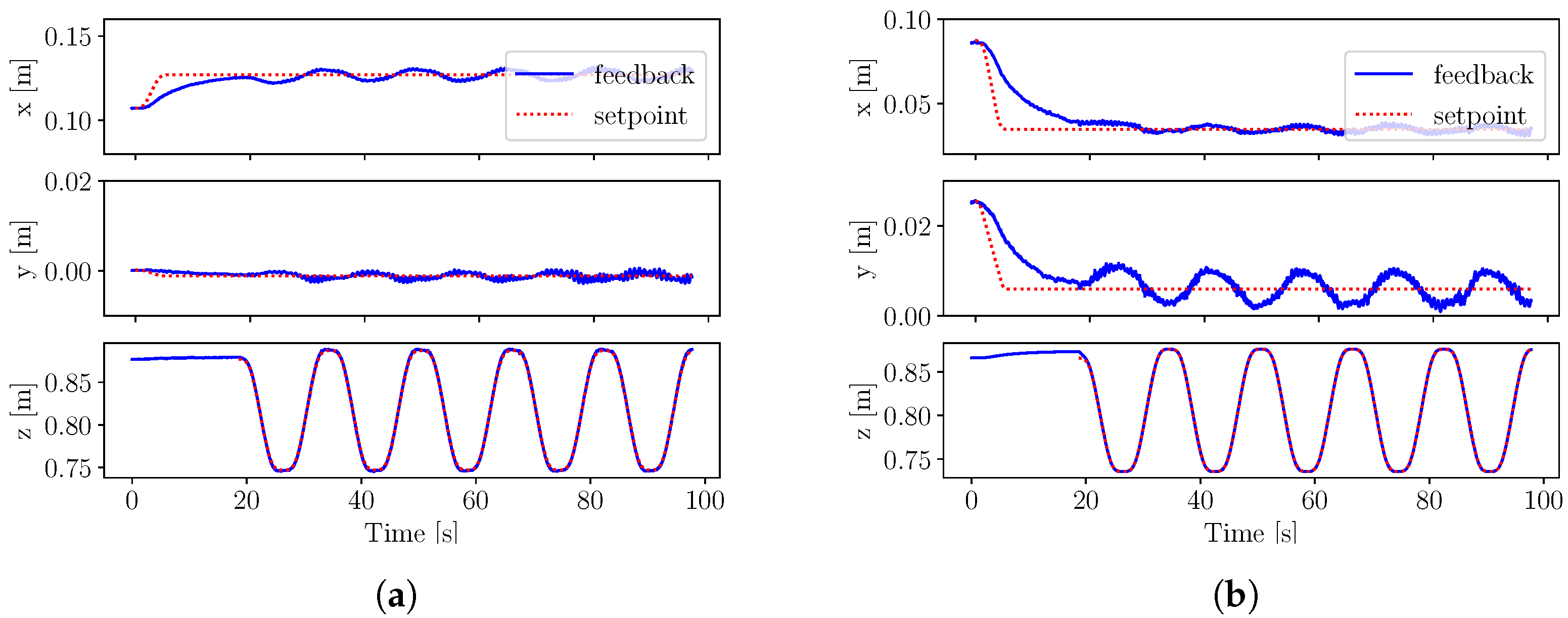
3.1. Squatting Experiment
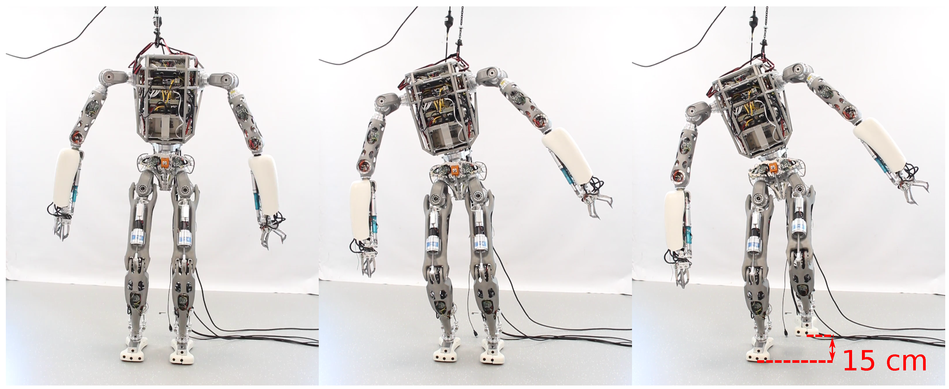
3.2. One Leg Balancing Experiment
4. Discussion
5. Conclusions
Supplementary Materials
Author Contributions
Funding
Institutional Review Board Statement
Informed Consent Statement
Data Availability Statement
Conflicts of Interest
References
- Boutin, L.; Eon, A.; Zeghloul, S.; Lacouture, P. An auto-adaptable algorithm to generate human-like locomotion for different humanoid robots based on motion capture data. In Proceedings of the 2010 IEEE/RSJ International Conference on Intelligent Robots and Systems, Taipei, Taiwan, 18–22 October 2010; pp. 1256–1261. [Google Scholar] [CrossRef]
- Miura, K.; Morisawa, M.; Nakaoka, S.; Kanehiro, F.; Harada, K.; Kaneko, K.; Kajita, S. Robot motion remix based on motion capture data towards human-like locomotion of humanoid robots. In Proceedings of the 2009 9th IEEE-RAS International Conference on Humanoid Robots, Paris, France, 7–10 December 2009; pp. 596–603. [Google Scholar] [CrossRef]
- Maroger, I.; Stasse, O.; Watier, B. Walking Human Trajectory Models and Their Application to Humanoid Robot Locomotion. In Proceedings of the 2020 IEEE/RSJ International Conference on Intelligent Robots and Systems (IROS), Las Vegas, NV, USA, 25–29 October 2020; pp. 3465–3472. [Google Scholar] [CrossRef]
- Ramos Ponce, O.E.; Mansard, N.; Stasse, O.; Benazeth, C.; Hak, S.; Saab, L. Dancing Humanoid Robots: Systematic use of OSID to Compute Dynamically Consistent Movements Following a Motion Capture Pattern. IEEE Robot. Autom. Mag. 2015, 22, 16–26. [Google Scholar] [CrossRef]
- Ramadoss, P.; Romualdi, G.; Dafarra, S.; Chavez, F.J.A.; Traversaro, S.; Pucci, D. DILIGENT-KIO: A Proprioceptive Base Estimator for Humanoid Robots using Extended Kalman Filtering on Matrix Lie Groups. arXiv 2021, arXiv:2105.14914. [Google Scholar]
- Sushrutha Raghavan, V.; Kanoulas, D.; Zhou, C.; Caldwell, D.G.; Tsagarakis, N.G. A Study on Low-Drift State Estimation for Humanoid Locomotion, Using LiDAR and Kinematic-Inertial Data Fusion. In Proceedings of the 2018 IEEE-RAS 18th International Conference on Humanoid Robots (Humanoids), Beijing, China, 6–9 November 2018; pp. 1–8. [Google Scholar] [CrossRef]
- Lasguignes, T.; Maroger, I.; Fallon, M.; Ramezani, M.; Marchionni, L.; Stasse, O.; Mansard, N.; Watier, B. ICP Localization and Walking Experiments on a TALOS Humanoid Robot. In Proceedings of the 2021 20th International Conference on Advanced Robotics (ICAR), Ljubljana, Slovenia, 6–10 December 2021; pp. 800–805. [Google Scholar] [CrossRef]
- Murphy, M.P.; Saunders, A.; Moreira, C.; Rizzi, A.A.; Raibert, M. The LittleDog robot. Int. J. Robot. Res. 2011, 30, 145–149. [Google Scholar] [CrossRef]
- Yim, J. Hopping Control and Estimation for a High-Performance Monopedal Robot, Salto-1P. Ph.D. Thesis, UC Berkeley, Berkeley, CA, USA, 2020. [Google Scholar]
- Ramirez-Alpizar, I.G.; Naveau, M.; Benazeth, C.; Stasse, O.; Laumond, J.P.; Harada, K.; Yoshida, E. Motion Generation for Pulling a Fire Hose by a Humanoid Robot. In Proceedings of the 16th IEEE-RAS International Conference on Humanoid Robotics (HUMANOIDS 2016), Cancun, Mexico, 15–17 November 2016. [Google Scholar]
- Eßer, J.; Kumar, S.; Peters, H.; Bargsten, V.; Fernandez, J.d.G.; Mastalli, C.; Stasse, O.; Kirchner, F. Design, analysis and control of the series-parallel hybrid RH5 humanoid robot. In Proceedings of the 2020 IEEE-RAS 20th International Conference on Humanoid Robots (Humanoids), Munich, Germany, 19–21 July 2021; pp. 400–407. [Google Scholar] [CrossRef]
- Mronga, D.; Kumar, S.; Kirchner, F. Whole-Body Control of Series-Parallel Hybrid Robots. In Proceedings of the 2022 International Conference on Robotics and Automation (ICRA), Philadelphia, PA, USA, 23–27 May 2022; IEEE: Piscataway Township, MJ, USA, 2022; pp. 228–234. [Google Scholar] [CrossRef]
- Hartley, R.; Jadidi, M.G.; Grizzle, J.; Eustice, R.M. Contact-Aided Invariant Extended Kalman Filtering for Legged Robot State Estimation. In Proceedings of the Robotics: Science and Systems XIV. Robotics: Science and Systems Foundation, Pennsylvania, PA, USA, 26–30 June 2018. [Google Scholar] [CrossRef]
- Kumar, S.; Wöhrle, H.; de Gea Fernández, J.; Müller, A.; Kirchner, F. A survey on modularity and distributivity in series-parallel hybrid robots. Mechatronics 2020, 68, 102367. [Google Scholar] [CrossRef]
- Rock, the Robot Construction Kit. Available online: http://www.rock-robotics.org (accessed on 11 December 2022).
- Barrau, A.; Bonnabel, S. The Invariant extended Kalman filter as a stable observer. IEEE Trans. Autom. Control 2017, 62, 1797–1812. [Google Scholar] [CrossRef]
- Solà, J.; Deray, J.; Atchuthan, D. A micro Lie theory for state estimation in robotics. arXiv 2018, arXiv:1812.01537. [Google Scholar]
- Ferreau, H.; Kirches, C.; Potschka, A.; Bock, H.; Diehl, M. qpOASES: A parametric active-set algorithm for quadratic programming. Math. Program. Comput. 2014, 6, 327–363. [Google Scholar] [CrossRef]
- Lynch, K.; Park, F. Modern Robotics; Cambridge University Press: Cambridge, MA, USA, 2017; pp. 85–89. [Google Scholar]
- Kumar, S.; Szadkowski, K.A.v.; Mueller, A.; Kirchner, F. An Analytical and Modular Software Workbench for Solving Kinematics and Dynamics of Series-Parallel Hybrid Robots. J. Mech. Robot. 2020, 12, 021114. [Google Scholar] [CrossRef]


| Experiment | Task | Weights | |||||
|---|---|---|---|---|---|---|---|
| Squatting | CoM | 6 | 6 | 0 | - | - | - |
| Root | 0 | 1 | 1 | 1 | 1 | 1 | |
| Balancing | CoM | 6 | 6 | 1 | - | - | - |
| Feet | 1 | 1 | 1 | 1 | 1 | 1 | |
| Wrists | 1 | 1 | 0 | 0 | 0 | 0 | |
| Experiment | State Feedback | RMSE [m] | ||||
|---|---|---|---|---|---|---|
| S1 (16 s) | MoCap Tracking | 0.004 | 0.004 | 0.001 | 0.001 | - |
| State Estimation | 0.008 | 0.007 | 0.004 | 0.001 | - | |
| S2 (10 s) | MoCap Tracking | 0.004 | 0.004 | 0.001 | 0.002 | - |
| State Estimation | 0.027 | 0.010 | 0.025 | 0.001 | - | |
| B1 (10 cm) | MoCap Tracking | 0.025 | 0.002 | 0.025 | 0.001 | 0.006 |
| State Estimation | 0.026 | 0.018 | 0.018 | 0.001 | 0.002 | |
| B2 (15 cm) | MoCap Tracking | 0.023 | 0.002 | 0.023 | 0.001 | 0.008 |
| State Estimation | 0.026 | 0.017 | 0.019 | 0.001 | 0.008 | |
Publisher’s Note: MDPI stays neutral with regard to jurisdictional claims in published maps and institutional affiliations. |
© 2022 by the authors. Licensee MDPI, Basel, Switzerland. This article is an open access article distributed under the terms and conditions of the Creative Commons Attribution (CC BY) license (https://creativecommons.org/licenses/by/4.0/).
Share and Cite
Popescu, M.; Mronga, D.; Bergonzani, I.; Kumar, S.; Kirchner, F. Experimental Investigations into Using Motion Capture State Feedback for Real-Time Control of a Humanoid Robot. Sensors 2022, 22, 9853. https://doi.org/10.3390/s22249853
Popescu M, Mronga D, Bergonzani I, Kumar S, Kirchner F. Experimental Investigations into Using Motion Capture State Feedback for Real-Time Control of a Humanoid Robot. Sensors. 2022; 22(24):9853. https://doi.org/10.3390/s22249853
Chicago/Turabian StylePopescu, Mihaela, Dennis Mronga, Ivan Bergonzani, Shivesh Kumar, and Frank Kirchner. 2022. "Experimental Investigations into Using Motion Capture State Feedback for Real-Time Control of a Humanoid Robot" Sensors 22, no. 24: 9853. https://doi.org/10.3390/s22249853
APA StylePopescu, M., Mronga, D., Bergonzani, I., Kumar, S., & Kirchner, F. (2022). Experimental Investigations into Using Motion Capture State Feedback for Real-Time Control of a Humanoid Robot. Sensors, 22(24), 9853. https://doi.org/10.3390/s22249853