
Trajectory Design for Multi-UAV-Aided Wireless Power Transfer toward Future Wireless Systems

Abstract
:1. Introduction
1.1. Background
1.2. Related Work and Motivation
1.3. Contributions
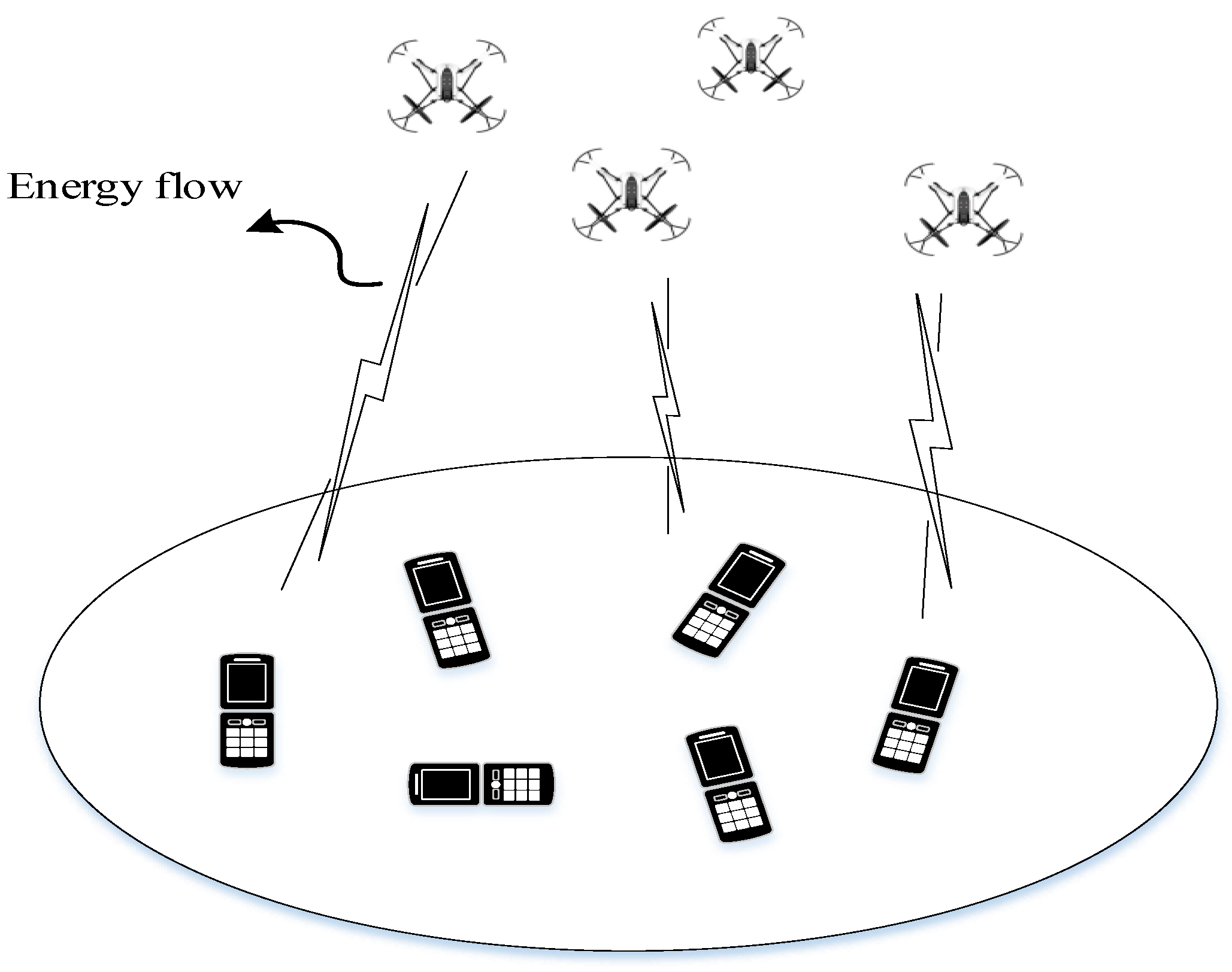
- Different from the existing works, we consider the UAV-enabled WPT system focusing on the cooperation of multiple UAVs to provide wireless energy to one ER on the ground. Under the constraints of UAV’s maximum speed and collision avoidance, we optimize the trajectories of UAVs to maximize the sum received energy of the ER.
- With the purpose of obtaining general conclusions, in Section 3, we conduct specific analysis about the cases where the number of UAVs is 1 and 2, respectively. In particular, we adopt the Lagrange multiplier method to solve the proposed optimization problem for a two-UAV-enabled WPT system.
- Based on the analysis of the one/two-UAV-enabled WPT system, the general conclusions are obtained in Section 4, which is beneficial to deduce the trajectories design of UAVs when the number of UAVs increases from three to seven. Furthermore, we also conduct a detailed analysis about the case where one UAV serves two ERs. Numerical results show that our presented trajectory design scheme is completely correct.
2. System Model
3. One/Two-UAV-Enabled WPT System
3.1. Special Case with = 1 UAV
3.2. Special Case with = 2 UAV
4. Multiple-UAV-Enabled WPT System with ≥ 3
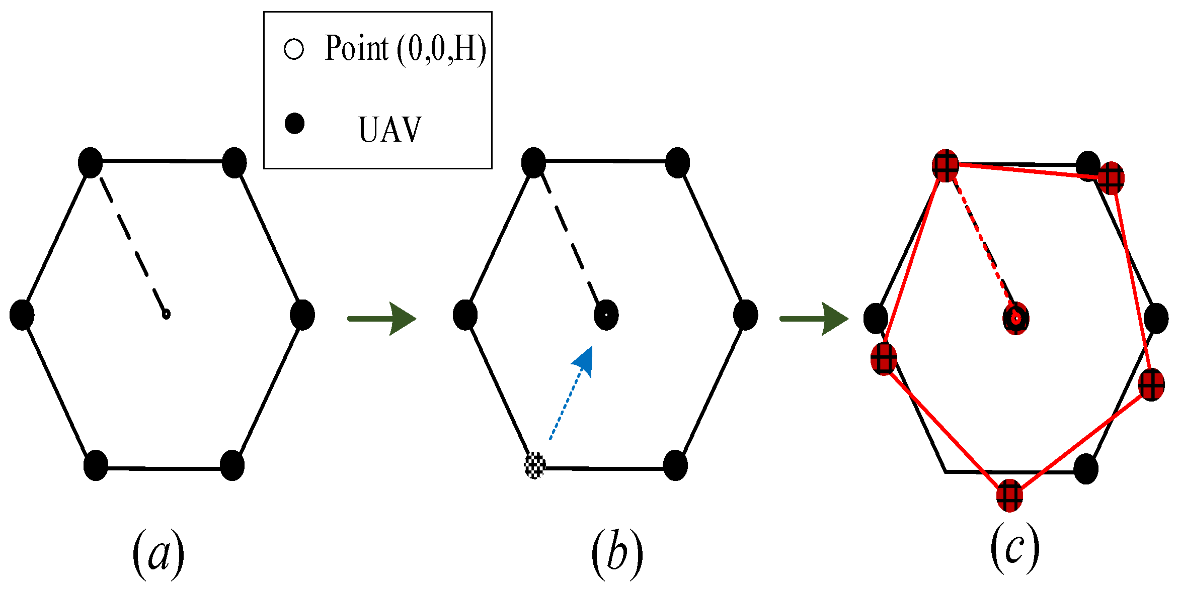
- When , the locations of the UAVs are symmetric, about . However, if , the safe distance constraint is negligible compared to the flight altitude. In this case, it is obvious that there is a symmetric relationship between any two UAVs in the optimization problem (7), which means that under the optimal path planning, the positions between any two UAVs can be exchanged without changing the relative positions of the UAVs and the ER.
- If one of the UAVs is deployed at a fixed location, the optimal trajectory design for other UAVs is independent of time t.
4.1. Special Case with = 3 UAVs
4.2. UAV-Enabled WPT System for > 3
4.3. UAV-Enabled WPT System for = 2
- When , we can obtain by calculating the maximization of . The UAV should hover at the coordinate of based on the optimal trajectory design scheme. At this moment, the total energy harvested is:
- When , we can obtain or by finding the maximization of . The UAV could hover at the coordinate of or based on the optimal trajectory design scheme, where At this moment, the total energy harvested is:
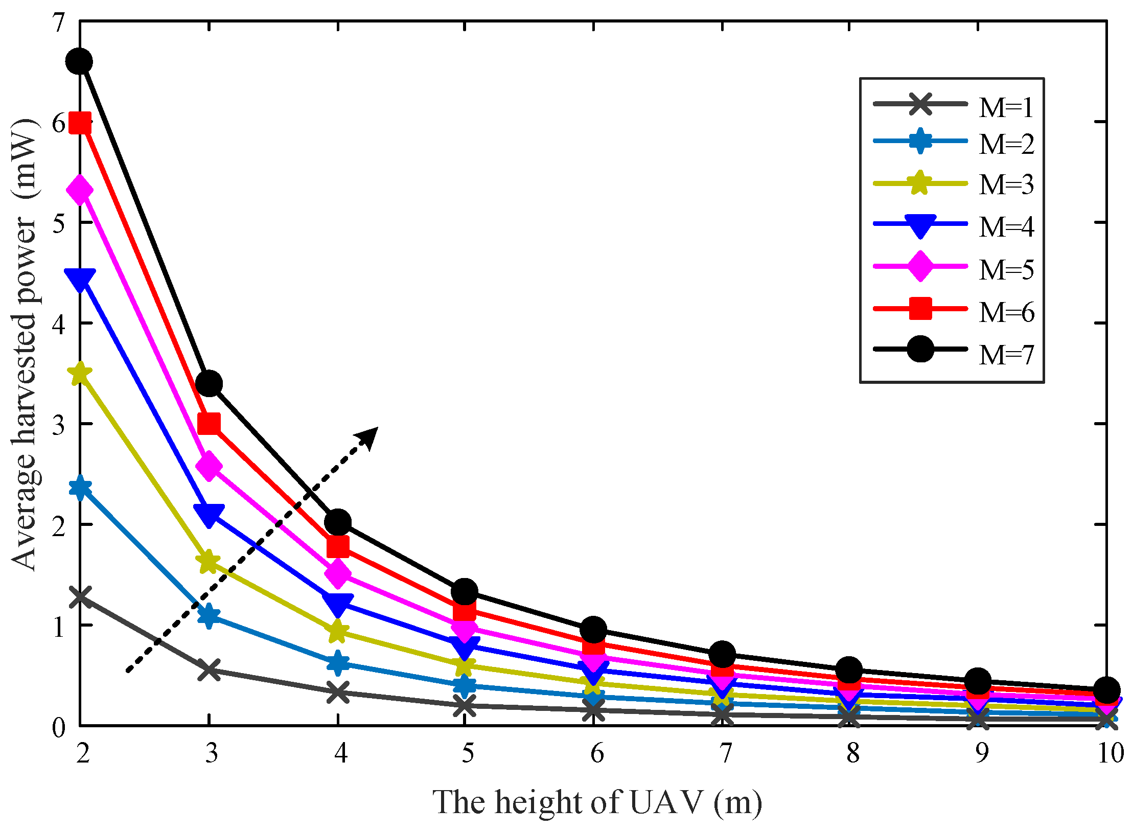
5. Simulation Results
6. Conclusions
Author Contributions
Funding
Institutional Review Board Statement
Informed Consent Statement
Data Availability Statement
Conflicts of Interest
Appendix A. Proof of Proposition 1
References
- Lu, X.; Wang, P.; Niyato, D.; Kim, D.I.; Han, Z. Wireless networks with RF energy harvesting: A contemporary survey. IEEE Commun. Surv. Tut. 2014, 17, 757–789. [Google Scholar] [CrossRef]
- Zeng, Y.; Clerckx, B.; Zhang, R. Communications and signals design for wireless power transmission. IEEE Trans. Commun. 2017, 65, 2264–2290. [Google Scholar] [CrossRef]
- Yang, P.; Xiao, Y.; Xiao, M.; Li, S. 6G wireless communications: Vision and potential techniques. IEEE Netw. 2019, 33, 70–75. [Google Scholar] [CrossRef]
- Gustavsson, U.; Frenger, P.; Fager, C.; Eriksson, T.; Zirath, H.; Dielacher, F.; Studer, C.; Pärssinen, A.; Correia, R.; Matos, J.N.; et al. Implementation challenges and opportunities in beyond-5G and 6G communication. IEEE J. Microw. 2021, 1, 86–100. [Google Scholar] [CrossRef]
- Tariq, F.; Khandaker, M.R.; Wong, K.K.; Imran, M.A.; Bennis, M.; Debbah, M. A speculative study on 6G. IEEE Wirel. Commun. 2020, 27, 118–125. [Google Scholar] [CrossRef]
- Zhang, H.; Shlezinger, N.; Guidi, F.; Dardari, D.; Imani, M.F.; Eldar, Y.C. Near-Field Wireless Power Transfer for 6G Internet of Everything Mobile Networks: Opportunities and Challenges. IEEE Commun. Mag. 2022, 60, 12–18. [Google Scholar] [CrossRef]
- Qi, Q.; Chen, X.; Zhong, C.; Zhang, Z. Integration of energy, computation and communication in 6G cellular internet of things. IEEE Commun. Lett. 2020, 24, 1333–1337. [Google Scholar] [CrossRef]
- Bi, S.; Ho, C.K.; Zhang, R. Wireless powered communication: Opportunities and challenges. IEEE Commun. Mag. 2015, 53, 117–125. [Google Scholar] [CrossRef]
- Lu, X.; Wang, P.; Niyato, D.; Kim, D.I.; Han, Z. Wireless charging technologies: Fundamentals, standards, and network applications. IEEE Commun. Surv. Tut. 2015, 18, 1413–1452. [Google Scholar] [CrossRef]
- Xu, J.; Zhang, R. Energy beamforming with one-bit feedback. IEEE Trans. Signal Process. 2014, 62, 5370–5381. [Google Scholar] [CrossRef] [Green Version]
- Xu, J.; Zeng, Y.; Zhang, R. UAV-enabled wireless power transfer: Trajectory design and energy optimization. IEEE Tran. Wirel. Commun. 2018, 17, 5092–5106. [Google Scholar] [CrossRef]
- Huda, S.; Arafat, M.Y.; Moh, S. Wireless Power Transfer in Wirelessly Powered Sensor Networks: A Review of Recent Progress. Sensors 2022, 22, 2952. [Google Scholar] [CrossRef]
- Zeng, Y.; Zhang, R.; Lim, T.J. Wireless communications with unmanned aerial vehicles: Opportunities and challenges. IEEE Commun. Mag. 2016, 54, 36–42. [Google Scholar] [CrossRef]
- Motlagh, N.H.; Taleb, T.; Arouk, O. Low-altitude unmanned aerial vehicles-based internet of things services: Comprehensive survey and future perspectives. IEEE Internet Things J. 2016, 3, 899–922. [Google Scholar] [CrossRef]
- Merwaday, A.; Guvenc, I. UAV assisted heterogeneous networks for public safety communications. In Proceedings of the 2015 IEEE Wireless Communications and Networking Conference Workshops, New Orleans, LA, USA, 9–12 March 2015; pp. 329–334. [Google Scholar]
- Mamaghani, M.T.; Hong, Y. Terahertz Meets Untrusted UAV-Relaying: Minimum Secrecy Energy Efficiency Maximization via Trajectory and Communication Co-design. IEEE Trans. Veh. Technol. 2022, 71, 4991–5006. [Google Scholar] [CrossRef]
- Song, Q.; Zeng, Y.; Xu, J.; Jin, S. A survey of prototype and experiment for UAV communications. Sci. China Inf. Sci. 2021, 64, 1–21. [Google Scholar] [CrossRef]
- Wu, Q.; Xu, J.; Zeng, Y.; Ng, D.W.K.; Al-Dhahir, N.; Schober, R.; Swindlehurst, A.L. A comprehensive overview on 5G-and-beyond networks with UAVs: From communications to sensing and intelligence. IEEE J. Sel. Areas Commun. 2021, 39, 2912–2945. [Google Scholar] [CrossRef]
- Al-Hourani, A.; Kandeepan, S.; Lardner, S. Optimal LAP altitude for maximum coverage. IEEE Wirel. Commun. Lett. 2014, 3, 569–572. [Google Scholar] [CrossRef]
- Alzenad, M.; El-Keyi, A.; Yanikomeroglu, H. 3-D placement of an unmanned aerial vehicle base station for maximum coverage of users with different QoS requirements. IEEE Wirel. Commun. Lett. 2017, 7, 38–41. [Google Scholar] [CrossRef]
- Lyu, J.; Zeng, Y.; Zhang, R.; Lim, T.J. Placement optimization of UAV-mounted mobile base stations. IEEE Commun. Lett. 2016, 21, 604–607. [Google Scholar] [CrossRef] [Green Version]
- Ye, Z.; Wang, K.; Chen, Y.; Jiang, X.; Song, G. Multi-UAV Navigation for Partially Observable Communication Coverage by Graph Reinforcement Learning. IEEE Trans. Mob. Comput. 2022. [Google Scholar] [CrossRef]
- Nemer, I.A.; Sheltami, T.R.; Belhaiza, S.; Mahmoud, A.S. Energy-Efficient UAV Movement Control for Fair Communication Coverage: A Deep Reinforcement Learning Approach. IEEE J. Sel. Areas Commun. 2018, 36, 2059–2070. [Google Scholar]
- Sharma, V.; Bennis, M.; Kumar, R. UAV-assisted heterogeneous networks for capacity enhancement. IEEE Commun. Lett. 2016, 20, 1207–1210. [Google Scholar] [CrossRef]
- Alzenad, M.; El-Keyi, A.; Lagum, F.; Yanikomeroglu, H. 3-D placement of an unmanned aerial vehicle base station (UAV-BS) for energy-efficient maximal coverage. IEEE Wirel. Commun. Lett. 2017, 6, 434–437. [Google Scholar] [CrossRef]
- Zhan, P.; Yu, K.; Swindlehurst, A.L. Wireless relay communications with unmanned aerial vehicles: Performance and optimization. IEEE Trans. Aerosp. Electron. Syst. 2011, 47, 2068–2085. [Google Scholar] [CrossRef]
- Na, Z.; Ji, C.; Lin, B.; Zhang, N. Joint optimization of trajectory and resource allocation in secure UAV relaying communications for Internet of Things. IEEE Internet Things J. 2022. [Google Scholar] [CrossRef]
- Huang, Y.; Wu, Q.; Lu, R.; Peng, X.; Zhang, R. Massive MIMO for cellular-connected UAV: Challenges and promising solutions. IEEE Commun. Mag. 2021, 59, 84–90. [Google Scholar] [CrossRef]
- Zeng, Y.; Zhang, R.; Lim, T.J. Throughput maximization for UAV-enabled mobile relaying systems. IEEE Trans. Commun. 2016, 64, 4983–4996. [Google Scholar] [CrossRef]
- Zeng, Y.; Zhang, R. Energy-efficient UAV communication with trajectory optimization. IEEE Trans. Wirel. Commun. 2017, 16, 3747–3760. [Google Scholar] [CrossRef]
- Pang, X.; Sheng, M.; Zhao, N.; Tang, J.; Niyato, D.; Wong, K.K. When UAV meets IRS: Expanding air-ground networks via passive reflection. IEEE Wirel. Commun. 2021, 28, 164–170. [Google Scholar] [CrossRef]
- Dao, N.N.; Pham, Q.V.; Tu, N.H.; Thanh, T.T.; Bao, V.N.Q.; Lakew, D.S.; Cho, S. Survey on aerial radio access networks: Toward a comprehensive 6G access infrastructure. IEEE Commun. Surv. Tutor. 2021, 23, 1193–1225. [Google Scholar] [CrossRef]
- Xu, J.; Zeng, Y.; Zhang, R. UAV-enabled wireless power transfer: Trajectory design and energy region characterization. In Proceedings of the 2017 IEEE Globecom Workshops (GC Wkshps), Singapore, 4–8 December 2017; pp. 1–7. [Google Scholar]
- Wu, Y.; Qiu, L.; Xu, J. UAV-enabled wireless power transfer with directional antenna: A two-user case. In Proceedings of the 2018 15th International Symposium on Wireless Communication Systems (ISWCS), Lisbon, Portugal, 28–31 August 2018; pp. 1–6. [Google Scholar]
- Yang, T.; Hu, Y.; Yuan, X.; Mathar, R. Genetic algorithm based UAV trajectory design in wireless power transfer systems. In Proceedings of the 2019 IEEE Wireless Communications and Networking Conference (WCNC), Marrakesh, Morocco, 15–18 April 2019; pp. 1–6. [Google Scholar]
- Ku, S.; Jung, S.; Lee, C. UAV trajectory design based on reinforcement learning for wireless power transfer. In Proceedings of the 2019 34th International Technical Conference on Circuits/Systems, Computers and Communications (ITC-CSCC), JeJu, Korea, 23–26 June 2019; pp. 1–3. [Google Scholar]
- Nguyen, K.K.; Masaracchia, A.; Sharma, V.; Poor, H.V.; Duong, T.Q. RIS-assisted UAV communications for IoT with wireless power transfer using deep reinforcement learning. IEEE J. Sel. Top. Signal Process. 2022. [Google Scholar] [CrossRef]
- Pham, Q.V.; Le, M.; Huynh-The, T.; Han, Z.; Hwang, W.J. Energy-efficient federated learning over UAV-enabled wireless powered communications. IEEE Trans. Veh. Technol. 2022, 71, 4977–4990. [Google Scholar] [CrossRef]
- Hu, Y.; Yuan, X.; Xu, J.; Schmeink, A. Optimal 1D trajectory design for UAV-enabled multiuser wireless power transfer. IEEE Trans. Commun. 2019, 67, 5674–5688. [Google Scholar] [CrossRef]
- Li, T.; Fan, P.; Chen, Z.; Letaief, K.B. Optimum transmission policies for energy harvesting sensor networks powered by a mobile control center. IEEE Trans. Wirel. Commun. 2016, 15, 6132–6145. [Google Scholar] [CrossRef]
- Park, J.; Lee, H.; Eom, S.; Lee, I. UAV-aided wireless powered communication networks: Trajectory optimization and resource allocation for minimum throughput maximization. IEEE Access 2019, 7, 134978–134991. [Google Scholar] [CrossRef]
- Xie, L.; Xu, J.; Zhang, R. Throughput maximization for UAV-enabled wireless powered communication networks. IEEE Internet Things J. 2018, 6, 1690–1703. [Google Scholar] [CrossRef]
- Xie, L.; Xu, J. Cooperative trajectory design and resource allocation for a two-UAV two-user wireless powered communication system. In Proceedings of the 2018 IEEE International Conference on Communication Systems (ICCS), Chengdu, China, 19–21 December 2018; pp. 7–12. [Google Scholar]
- Xie, L.; Xu, J. Common Throughput Maximization for UAV-Enabled Interference Channel With Wireless Powered Communications. IEEE Trans. Commun. 2020, 68, 3197–3212. [Google Scholar] [CrossRef] [Green Version]
- Boyd, S.; Boyd, S.P.; Vandenberghe, L. Convex Optimization; Cambridge University Press: Cambridge, UK, 2004. [Google Scholar]


| Parameter | Value |
|---|---|
| UAV’s transmit power | 40 dBm |
| UAV’s height | 5 m |
| Channel gain | −30 dB |
| Safe distance | 1 m |
Publisher’s Note: MDPI stays neutral with regard to jurisdictional claims in published maps and institutional affiliations. |
© 2022 by the authors. Licensee MDPI, Basel, Switzerland. This article is an open access article distributed under the terms and conditions of the Creative Commons Attribution (CC BY) license (https://creativecommons.org/licenses/by/4.0/).
Share and Cite
Mu, J.; Sun, Z. Trajectory Design for Multi-UAV-Aided Wireless Power Transfer toward Future Wireless Systems. Sensors 2022, 22, 6859. https://doi.org/10.3390/s22186859
Mu J, Sun Z. Trajectory Design for Multi-UAV-Aided Wireless Power Transfer toward Future Wireless Systems. Sensors. 2022; 22(18):6859. https://doi.org/10.3390/s22186859
Chicago/Turabian StyleMu, Jun, and Zhaojie Sun. 2022. "Trajectory Design for Multi-UAV-Aided Wireless Power Transfer toward Future Wireless Systems" Sensors 22, no. 18: 6859. https://doi.org/10.3390/s22186859
APA StyleMu, J., & Sun, Z. (2022). Trajectory Design for Multi-UAV-Aided Wireless Power Transfer toward Future Wireless Systems. Sensors, 22(18), 6859. https://doi.org/10.3390/s22186859