Abstract
Unmanned aerial vehicles (UAVs) have been widely considered to enhance the communication coverage, as well as the wireless power transfer (WPT) of energy-constrained communication networks to prolong their lifetime. However, the trajectory design of a UAV in such a system remains a key problem, especially considering the three-dimensional (3D) feature of the UAV. To address this issue, a UAV-assisted dual-user WPT system was investigated in this paper, where a UAV-mounted energy transmitter (ET) flies in the air to broadcast wireless energy to charge the energy receivers (ERs) on the ground. By optimizing the UAV’s 3D trajectory toward a balanced tradeoff between energy consumption and WPT performance, the energy harvested by all ERs during a given mission period was maximized. The above goal was achieved through the following detailed designs. On the one hand, on the basis of previous research results, there is a one-to-one correspondence between the UAV’s abscissa and height, so only the relationship between the height and time was focused on in this work to obtain the UAV’s optimal 3D trajectory. On the other hand, the idea of calculus was employed to calculate the total harvested energy, leading to the proposed high-efficiency trajectory design. Finally, the simulation results demonstrated that this contribution is capable of enhancing the energy supply by carefully designing the 3D trajectory of the UAV, compared to its conventional counterpart. In general, the above-mentioned contribution could be a promising way for UAV-aided WPT in the future Internet of Things (IoT) and wireless sensor networks (WSNs).
1. Introduction
In recent years, the use of unmanned aerial vehicles (UAVs) has been widely considered for wireless communications, due to their deployment flexibility and controllable mobility [1,2,3]. Specifically, UAVs have been explored to improve the security of wireless information delivery [4], to enhance the wireless connection as a reliable relay [5,6], to break through the energy supply bottleneck of wireless networks [7,8], and to provide a stable and reliable communication framework [9,10]. Meanwhile, UAVs can be well integrated with current pioneering wireless transmission techniques such as reconfigurable intelligent surface (RIS) [11], millimeter-wave (mmWave) [12], and terahertz [13]. Therefore, they are also considered as a flexible new type of base station or relay toward the realization of the sixth-generation networks [14,15]. Furthermore, the Internet of Things (IoT) remains an important scenario for 6G wireless networks [16,17], and the energy supply for long-term work still remains a big problem. Therefore, with the aid of a UAV, while exploring the new design freedom from the air, the new construction of wireless power transfer (WPT) has attracted much attention in order to generate a more efficient and stable energy supply to break through the bottleneck of the IoT network [18,19]. Another advantage lies in that, due to the multi-dimensional moving freedom of the UAV, the original WPT connection can be enhanced by avoiding blockage and shadow fading, so that the transmission channel can be simplified to a line-of-sight (LoS) one thanks to the introduction of the UAV [20,21]. As a result, UAVs can significantly enhance the WPT performance while offering stable supply to the fixed-location energy transmitters (ETs) compared to the conventional WPT systems.
Due to the above-mentioned advantages and potentials, UAV-aided WPT systems have been widely investigated in the literature. For example, the authors in [22] first considered a novel WPT architecture, where UAVs were utilized as mobile ETs to provide wireless energy to charge a number of ERs deployed on the ground. By making full use of the controllable mobility of the UAV, the WPT efficiency of the new WPT system is anticipated to be greatly improved by a rational trajectory design. In addition, positioning and trajectory designs for UAVs to maximize the energy transfer efficiency were also studied in [23,24,25,26,27,28]. Xu et al. [18] maximized the transferred energy amounts towards all ERs during the charging period, and min-energy maximization was considered in [23,24,25] to improve the fairness. Jiang et al. [26], Xie et al. [27], and Cho et al. [28] investigated the cooperative UAV trajectory design and wireless resource allocation problem for simultaneous wireless information and power transfer (SWIPT) systems. However, most of the aforementioned works considered the UAVs flying at a constant altitude in the sky. To efficiently employ the UAV as a WPT source to power ground ERs, a precise three-dimensional (3D) trajectory design must be conducted to meet the needs of the energy-limited ground users.
According to the above-mentioned issue, the most-important design problem in UAV-aided WPT systems is carefully controlling the flying routes with the high demand of energy efficiency. In pursuit of an economic and efficient trajectory design, recently, in [18], the maximization of the sum-energy was achieved through a more efficient trajectory design for the UAV and ground ERs, which indicates that there is a one-to-one mapping of the UAV’s abscissa to the height. Motivated by [18], the UAV’s 3D trajectory was optimized to maximize the amount of transferred energy at all receivers during the charging period in this paper.
Different from previous works, it was assumed that the UAV flies within the height range of , where is the height of the charging pile and is the target height of the UAV. The main research contributions are described as follows:
- This paper gives a brief description of the so-called problem of maximizing the sum-energy for enhancing the energy supply. That is to say, this work focused on maximizing the achievable energy for all ERs during a given charging period by optimizing the UAV’s 3D trajectory.
- This work further optimized the relationship between the UAV’s altitude and time to obtain the UAV’s 3D trajectory according to the results in [18]; in addition, the total harvested energy was calculated with the idea of calculus.
- The theoretical and numerical results demonstrated that the proposed design outperformed the benchmark schemes in terms of higher energy transferred to all ERs.
On the one hand, the UAV’s 3D trajectory was efficiently optimized compared to the current literature, so as to make a balanced tradeoff between energy harvesting and consumption. On the other hand, after a careful design, the energy harvested by all ERs during a given mission period was maximized for WPT.
The remainder of this paper is organized as follows. The detailed system model and general sum-energy maximization problem for the UAV-aided WPT are introduced in Section 2. In Section 3, the optimization problem of the 3D trajectory design of the UAV-aided WPT system is explored. Finally, numerical results are presented in Section 4 to demonstrate the effectiveness of the proposed method, and the paper is concluded in Section 5.
2. System Model
In general, the UAV-aided WPT system can be described by Figure 1. For some special transmission environments such as the IoT, the energy of the device is limited due to the size and the stationary of the device. Then, in the considered system, the UAV serves as a special energy supply for the users. Considering the freedom of space, the 3D trajectory was developed. In the context of a UAV-aided dual-user wireless power transmission system, the UAV was utilized to deliver the energy to two energy-limited nodes. Each ER, has an unchanged location on the ground, which is a priori known to the UAV to facilitate its trajectory design. We focused on a given mission period with duration T, which generally depends on the energy stored by the UAV. The UAV was assumed to fly within the altitude range , so that the path for the wireless power transmission between the UAV and ER was, respectively, assumed to be an LoS channel. As a result, this paper can adopt the traditional LoS channel model in the free space as in [22,23,24]. At time instant t, the UAV’s time-varying location is denoted as . As a result, the channel power gain from the UAV to ER k can be modeled as
where
stands for the distance from the UAV to each independent ER, while is represented by the power of the transmission channel gain built on a reference distance as m. When the transmit power of the UAV is fixed to be P, at each time t, the power harvested by ER k can be written as and can be further expressed as
where is a real number between 0 and 1, standing for the efficiency of the energy delivery and conversion at each side of the ER. Therefore, based on the UAV’s trajectory which was the optimization objective of this paper, the sum-energy harvested through ER k during the whole UAV-aided WPT period T is written as and is further expressed as
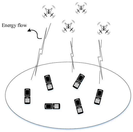
Figure 1.
The system model of UAV-aided WPT.
Then, based on the above model, the design goal of this paper was to maximize the energy harvested from all the ERs through optimizing the trajectory of the UAV as . Specifically, the so-called sum-energy maximization process can be summarized as
Although the above model could be a representation of the UAV-aided WPT design, the optimal theoretical solution may still be hard to achieve, since the harvested energy in (4) is a non-concave function of the UAV’s trajectory. Therefore, the solution to the problem in (5) is also a non-convex optimization one that cannot be easily solved using traditional ways. Therefore, in order to address this issue, this work utilized the results in [18], so there is a parallel relation between the UAV’s abscissa and height. Consequently, only the relationship between the height and time need to be optimized to obtain the optimal UAV 3D trajectory.
3. Optimal Trajectory Design
It is noted that setting the ordinate of the UAV as is reasonable, which would greatly simplify the optimization problem. Additionally, according to the analysis in [18], can be viewed as a function of the height , which can be expressed as
where D is the distance between two ERs. According to (6), the UAV’s flight trajectory diagram can be drawn as shown in Figure 2. At the same time, the relationship between the UAV’s abscissa and height is shown in Figure 3. Assuming , the mission period T is long enough and the UAV flies at a constant velocity V. Suppose that the UAV reaches the height of at time and hovers there for a period of , then it would return to the initial point at the speed of V for charging and waiting for the next mission.
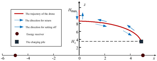
Figure 2.
The trajectory design for a two-user WPT system.
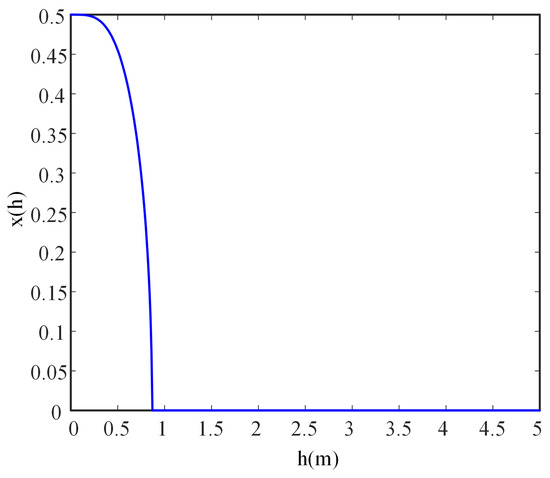
Figure 3.
The relationship between the UAV’s abscissa and height.
Obviously, the trajectory shown in Figure 2 consists of a straight line and a curve. Firstly, the idea of calculus can be adopted to obtain the length of the curve. Specifically, dividing the interval into N equal parts, the step size is expressed as
This paper denotes the i-th interval as , where and . As shown in Figure 4, when the step size is small enough, the flight path corresponding to can be approximated as a straight line, whose length can be calculated by the triangle marked in Figure 4 with the formula . Additionally, the flight period over it is , during which, assuming that the UAV hovers at position , then the total energy collected during this period is
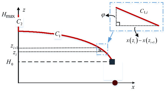
Figure 4.
Calculating the received energy with calculus.
As a consequence, the total length of the curve is
the total collected energy is
and the time for the UAV to reach point is
Note that the length of the straight line is
and the time required is
Suppose that the UAV rises a distance from with time , then the coordinate of the UAV is , and the total received power of the two energy receivers is expressed as
Therefore, the total energy received by the two energy receivers when the UAV rises from to is expressed as
Finally, the UAV would hover at for a period of . During this period, the total energy collected by the energy receivers is written as
To sum up, in the case of sufficient mission period T, the total energy obtained by the energy receiver is
During the mission period T, for any time , the UAV’s coordinate under the optimal trajectory is given by
As theoretically derived in the above, for UAV-aided WPT systems, the UAV can obtain an optimal trajectory as a balanced tradeoff between the energy efficiency and the overall performance. In the next section, the simulation results will be given to prove the effectiveness of the designed 3D trajectory. The details are summarized in Algorithm 1.
| Algorithm 1: UAV trajectory design algorithm. |
| Require: Initialize , , P,, , , v Output: , , ,
|
4. Numerical Results
In this section, the wireless energy transmission performance of the two-user UAV-enabled WPT system is provided to verify the effectiveness of the 3D UAV path-planning algorithm proposed in Section 3. The specific simulation parameters are shown in Table 1 and Table 2 to describe the transmission environment.

Table 1.
Summary of main notations.

Table 2.
Simulation parameters of two-user WPT system.
For the above-described configuration, Figure 5 exhibits the convergence analysis of the total collected energy shown in Formula (10). In the simulation, let m, m, m, and m/s. The relationship between the average received energy and N is drawn to validate that employing calculus to obtain the harvested energy is feasible, because when N is large enough, the average received energy tends to be a constant. In this case, enough energy supply is expected to support the devices, which is important for energy-limited networks such as the IoT. However, this additional energy supply is achieved at the cost of the energy of the UAV.
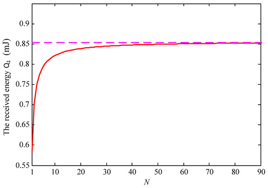
Figure 5.
Convergence analysis of the proposed scheme.
Considering different mobile speed V, Figure 6, Figure 7 and Figure 8 disclose the relationship between the total energy received by the ERs and the mission period T. Suppose that the process of the UAV flying over curves and and hovering at the highest place is denoted as Stage 1, Stage 2, and Stage 3, respectively. It is observed from the figures that the total received energy increases with the task period T, as expected. Specifically, when m/s, we arrive at in Figure 6, which denotes that the UAV starts to return to the starting point before it reaches directly above the midpoint of the two energy receivers. Therefore, the UAV will not go through Stage 2 and Stage 3. Furthermore, when m/s in Figure 7, we arrive at , which denotes that the UAV continues to rise after reaching the position , but returns before reaching the highest altitude. When m/s in Figure 8, we arrive at , and the UAV reaches the highest point and hovers here for a period of , then starts to return. As can be seen from the figures, the curve corresponding to the third stage is a straight line with a slope of , which is consistent with the conclusion in (16). In addition, this work also provides the total energy received by the system when the charging pile is built at the point to compare the performance. In a nutshell, we demonstrated that the method proposed in this paper achieved significant performance gains. In Figure 9, the total received energy is compared between the proposed optimal path algorithm and the successive hover-and-fly trajectory scheme [18], which is only set as the locations above all ERs, rather than optimizing the UAV’s hovering locations during a given mission period. It was observed that the proposed trajectory design provides better performance than the successive hover-and-fly path.
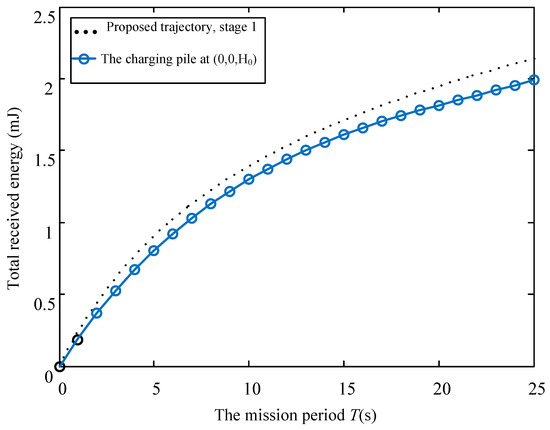
Figure 6.
The relationship between total received energy and mission period T with V = 0.2.
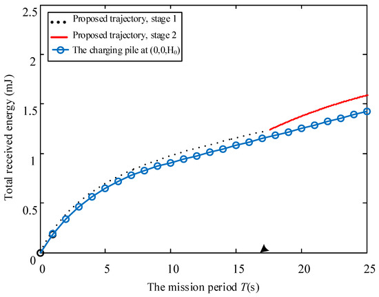
Figure 7.
The relationship between total received energy and mission period T with V = 0.4.
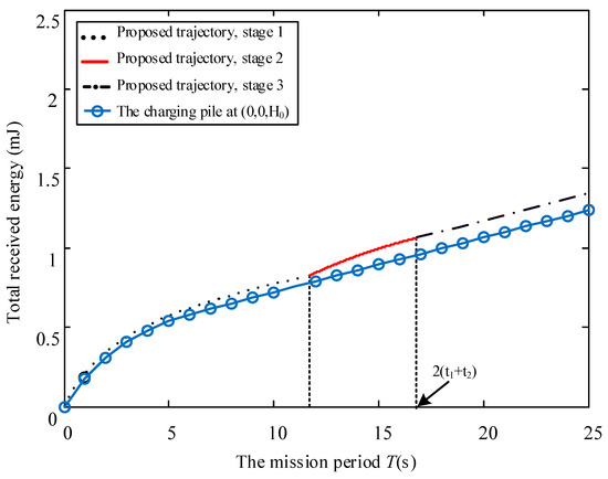
Figure 8.
The relationship between total received energy and mission period T with V = 0.6.
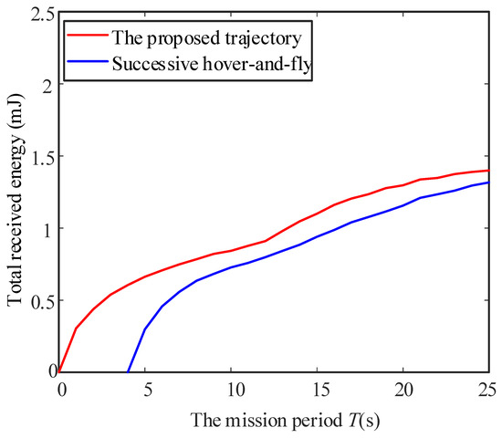
Figure 9.
The total received energy between the proposed optimal path algorithm and the successive hover-and-fly trajectory scheme.
Through the theoretical derivation and simulation results of this contribution, this paper demonstrated that the UAV can be extended to WPT systems to support energy-limited users with IoT sensors and low-cost devices. That is to say, the UAV may be a candidate energy supplier for the IoT to maintain its work. However, this advantage comes at that cost of additional energy consumption at the UAV side, which should be carefully considered for a balanced tradeoff through the trajectory design for the UAV. Considering the space freedom offered by the air, a more flexible 3D trajectory design is effective for such a system.
5. Conclusions
In this work, the UAV 3D trajectory optimization problem was investigated to maximize the total received energy in a wireless system, based on the assumption that the UAV is dispatched to charge two ground nodes through radio frequency wireless power transfer. The main contribution of this work can be summarized as follows. On the one hand, the optimization problem was ultimately solved by optimizing the relationship between the height and time according to the one-to-one correspondence between the UAV’s abscissa and height, through theoretical derivation. On the other hand, the sum-received-energy among all ERs was modeled and then calculated by calculus to arrive at an accurate solution. Finally, the numerical results demonstrated that the maximal attainable energy was increased with the proposed design. Specifically, compared to conventional counterpart [18], an energy increase of 20% can be achieved through the proposed 3D trajectory design.
Author Contributions
Conceptualization, X.G., Z.S. and K.H.; Software, X.G. and Z.S.; Writing—original draft, X.G.; Writing—review & editing, Z.S. and K.H. All authors have read and agreed to the published version of the manuscript.
Funding
This research was funded by National Key R&D Program of China (2020YFB1807203) and Sichuan Science and Technology Program (Grant No. 2021YFH0164).
Institutional Review Board Statement
Not applicable.
Informed Consent Statement
Not applicable.
Data Availability Statement
Not applicable.
Conflicts of Interest
The authors declare no conflict of interest.
References
- Zeng, Y.; Zhang, R.; Lim, T.J. Wireless communications with unmanned aerial vehicles: Opportunities and challenges. IEEE Commun. Mag. 2016, 54, 36–42. [Google Scholar] [CrossRef]
- Raja, G.; Anbalagan, S.; Ganapathisubramaniyan, A.; Selvakumar, M.S.; Bashir, A.K.; Mumtaz, S. Efficient and secured swarm pattern multi-UAV communication. IEEE Trans. Veh. Technol. 2021, 70, 7050–7058. [Google Scholar] [CrossRef]
- Ribeiro, L.M.B.; Müller, I.; Buss Becker, L. Communication interface manager for improving performance of heterogeneous UAV networks. Sensors 2021, 21, 4255. [Google Scholar] [CrossRef]
- Yan, S.; Hanly, S.V.; Collings, I.B. Optimal transmit power and flying location for UAV covert wireless communications. IEEE J. Sel. Areas Commun. 2021, 39, 3321–3333. [Google Scholar] [CrossRef]
- Sun, G.; Li, J.; Wang, A.; Wu, Q.; Sun, Z.; Liu, Y. Secure and Energy-Efficient UAV Relay Communications Exploiting Collaborative Beamforming. IEEE Trans. Commun. 2022, 70, 5401–5416. [Google Scholar] [CrossRef]
- Li, R.; Xiao, Y.; Yang, P.; Tang, W.; Wu, M.; Gao, Y. UAV-aided two-way relaying for wireless communications of intelligent robot swarms. IEEE Access 2020, 8, 56141–56150. [Google Scholar] [CrossRef]
- Xiong, Z.; Zhang, Y.; Lim, W.Y.B.; Kang, J.; Niyato, D.; Leung, C.; Miao, C. UAV-assisted wireless energy and data transfer with deep reinforcement learning. IEEE Trans. Cogn. Commun. Netw. 2020, 7, 85–99. [Google Scholar] [CrossRef]
- Hernández-González, O.; Guerrero-Sánchez, M.E.; Farza, M.; Ménard, T.; M’Saad, M.; Lozano, R. High gain observer for a class of nonlinear systems with coupled structure and sampled output measurements: Application to a quadrotor. Int. J. Syst. Sci. 2019, 50, 1089–1105. [Google Scholar] [CrossRef]
- Kumar, K.; Kumar, S.; Kaiwartya, O.; Sikandar, A.; Kharel, R.; Mauri, J.L. Internet of unmanned aerial vehicles: QoS provisioning in aerial ad-hoc networks. Sensors 2020, 20, 3160. [Google Scholar] [CrossRef]
- Jha, S.K.; Prakash, S.; Rathore, R.S.; Mahmud, M.; Kaiwartya, O.; Lloret, J. Quality-of-service-centric design and analysis of unmanned aerial vehicles. Sensors 2022, 22, 5477. [Google Scholar] [CrossRef]
- Nguyen, K.K.; Masaracchia, A.; Sharma, V.; Poor, H.V.; Duong, T.Q. RIS-assisted UAV communications for IoT with wireless power transfer using deep reinforcement learning. IEEE J. Sel. Top. Signal Process. 2022, 16, 1086–1096. [Google Scholar] [CrossRef]
- Xia, W.; Rangan, S.; Mezzavilla, M.; Lozano, A.; Geraci, G.; Semkin, V.; Loianno, G. Generative neural network channel modeling for millimeter-wave UAV communication. IEEE Trans. Wireless Commun. 2022, 21, 9417–9431. [Google Scholar] [CrossRef]
- Pan, Y.; Wang, K.; Pan, C.; Zhu, H.; Wang, J. UAV-assisted and intelligent reflecting surfaces-supported terahertz communications. IEEE Wireless Commun. Lett. 2021, 10, 1256–1260. [Google Scholar] [CrossRef]
- Geraci, G.; Garcia-Rodriguez, A.; Azari, M.M.; Lozano, A.; Mezzavilla, M.; Chatzinotas, S.; Chen, Y.; Rangan, S.; Di Renzo, M. What will the future of UAV cellular communications be? A flight from 5G to 6G. IEEE Commun. Surveys Tuts. 2022, 24, 1304–1335. [Google Scholar] [CrossRef]
- Yang, P.; Xiao, Y.; Xiao, M.; Li, S. 6G wireless communications: Vision and potential techniques. IEEE Netw. 2019, 33, 70–75. [Google Scholar] [CrossRef]
- Nguyen, D.C.; Ding, M.; Pathirana, P.N.; Seneviratne, A.; Li, J.; Niyato, D.; Dobre, O.; Poor, H.V. 6G Internet of Things: A comprehensive survey. IEEE Internet Things J. 2021, 9, 359–383. [Google Scholar] [CrossRef]
- Ma, Z.; Xiao, M.; Xiao, Y.; Pang, Z.; Poor, H.V.; Vucetic, B. High-reliability and low-latency wireless communication for internet of things: Challenges, fundamentals, and enabling technologies. IEEE Internet Things J. 2019, 6, 7946–7970. [Google Scholar] [CrossRef]
- Xu, J.; Zeng, Y.; Zhang, R. UAV-enabled wireless power transfer: Trajectory design and energy optimization. IEEE Trans. Wireless Commun. 2018, 17, 5092–5106. [Google Scholar] [CrossRef]
- Hu, Y.; Yuan, X.; Zhang, G.; Schmeink, A. Sustainable wireless sensor networks with UAV-enabled wireless power transfer. IEEE Trans. Veh. Technol. 2021, 70, 8050–8064. [Google Scholar] [CrossRef]
- Xie, L.; Xu, J.; Zhang, R. Throughput maximization for UAV-enabled wireless powered communication networks. IEEE Internet Things J. 2018, 6, 1690–1703. [Google Scholar] [CrossRef]
- Wu, Q.; Xu, J.; Zhang, R. Capacity characterization of UAV-enabled two-user broadcast channel. IEEE J. Sel. Areas Commun. 2018, 36, 1955–1971. [Google Scholar] [CrossRef]
- Xu, J.; Zeng, Y.; Zhang, R. UAV-enabled wireless power transfer: Trajectory design and energy region characterization. In Proceedings of the 2017 IEEE Globecom Workshops (GC Wkshps), Singapore, 4–8 December 2017; pp. 1–7. [Google Scholar]
- Hu, Y.; Yuan, X.; Xu, J.; Schmeink, A. Optimal 1D trajectory design for UAV-enabled multiuser wireless power transfer. IEEE Trans. Commun. 2019, 67, 5674–5688. [Google Scholar] [CrossRef]
- Xu, J.; Zeng, Y.; Zhang, R. UAV-enabled multiuser wireless power transfer: Trajectory design and energy optimization. In Proceedings of the 2017 23rd Asia-Pacific Conference on Communications (APCC), Perth, WA, Australia, 11–13 December 2017; pp. 1–6. [Google Scholar]
- Huang, F.; Chen, J.; Wang, H.; Ding, G.; Xue, Z.; Yang, Y.; Song, F. UAV-assisted SWIPT in Internet of Things with power splitting: Trajectory design and power allocation. IEEE Access 2019, 7, 68260–68270. [Google Scholar] [CrossRef]
- Jiang, M.; Li, Y.; Zhang, Q.; Qin, J. Joint position and time allocation optimization of UAV enabled time allocation optimization networks. IEEE Trans. Commun. 2019, 67, 3806–3816. [Google Scholar] [CrossRef]
- Najmeddin, S.; Bayat, A.; Aïssa, S.; Tahar, S. Energy-efficient resource allocation for UAV-enabled wireless powered communications. In Proceedings of the 2019 IEEE Wireless Communications and Networking Conference (WCNC), Marrakesh, Morocco, 15–18 April 2019; pp. 1–6. [Google Scholar]
- Cho, S.; Lee, K.; Kang, B.; Koo, K.; Joe, I. Weighted harvest-then-transmit: UAV-enabled wireless powered communication networks. IEEE Access 2018, 6, 72212–72224. [Google Scholar] [CrossRef]
Disclaimer/Publisher’s Note: The statements, opinions and data contained in all publications are solely those of the individual author(s) and contributor(s) and not of MDPI and/or the editor(s). MDPI and/or the editor(s) disclaim responsibility for any injury to people or property resulting from any ideas, methods, instructions or products referred to in the content. |
© 2023 by the authors. Licensee MDPI, Basel, Switzerland. This article is an open access article distributed under the terms and conditions of the Creative Commons Attribution (CC BY) license (https://creativecommons.org/licenses/by/4.0/).
