
Dual-Band CPW Graphene Antenna for Smart Cities and IoT Applications

 ,
,  ,
,  ,
,  and
and
Abstract
:1. Introduction
2. Materials and Methods
3. Results and Discussion
4. Conclusions
Author Contributions
Funding
Conflicts of Interest
References
- Lee, S.K.; Bae, M.; Kim, H. Future of IoT Networks: A Survey. Appl. Sci. 2017, 7, 1072. [Google Scholar] [CrossRef]
- Ma, D.; Lan, G.; Hassan, M.; Hu, W.; Das, S.K. Sensing, Computing, and Communications for Energy Harvesting IoTs: A Survey. IEEE Commun. Surv. Tutor. 2020, 22, 1222–1250. [Google Scholar] [CrossRef]
- Vaezi, M.; Azari, A.; Khosravirad, S.R.; Shirvanimoghaddam, M.; Azari, M.M.; Chasaki, D.; Popovski, P. Cellular, Wide-Area, and Non-Terrestrial IoT: A Survey on 5G Advances and the Road Toward 6G. IEEE Commun. Surv. Tutor. 2020, 24, 1117–1174. [Google Scholar] [CrossRef]
- Jabbar, W.A.; Kian, T.K.; Ramli, R.M.; Zubir, S.N.; Zamrizaman, N.S.M.; Balfaqih, M.; Shepelev, V.; Alharbi, S. Design and Fabrication of Smart Home with Internet of Things Enabled Automation System. IEEE Access 2019, 7, 144059–144074. [Google Scholar] [CrossRef]
- Roque-Cilia, S.; Tamariz-Flores, E.I.; Torrealba-Meléndez, R.; Covarrubias-Rosales, D.H. Transport tracking through communication in WDSN for smart cities. Measurement 2019, 139, 205–212. [Google Scholar] [CrossRef]
- Burlacu, M.; Boboc, R.G.; Butilă, E.V. Smart Cities and Transportation: Reviewing the Scientific Character of the Theories. Sustainability 2022, 14, 8109. [Google Scholar] [CrossRef]
- Almeida, V.A.; Doneda, D.; da Costa, E.M. Humane Smart Cities: The Need for Governance. IEEE Internet Comput. 2018, 22, 91–95. [Google Scholar] [CrossRef]
- Rodrigues, V.F.; Righi, R.D.R.; da Costa, C.A.; Antunes, R.S. Smart Hospitals and IoT Sensors: Why Is QoS Essential Here? J. Sens. Actuator Netw. 2022, 11, 33. [Google Scholar] [CrossRef]
- Venkatesh, J.; Aksanli, B.; Chan, C.S.; Akyurek, A.S.; Rosing, T.S. Modular and Personalized Smart Health Application Design in a Smart City Environment. IEEE Internet Things J. 2018, 5, 614–623. [Google Scholar] [CrossRef]
- Wang, Y.; Zen, H.; Sabri, M.F.M.; Wang, X.; Kho, L.C. Towards Strengthening the Resilience of IoV Networks—A Trust Management Perspective. Futur. Internet 2022, 14, 202. [Google Scholar] [CrossRef]
- Tamariz-Flores, E.I.; Torrealba-Meléndez, R. Vehicular Network Systems in Smart Cities. In Handbook of Smart Cities; Augusto, J.C., Ed.; Springer: Cham, Switzerland, 2020. [Google Scholar] [CrossRef]
- Teixeira, L.H.; Huszák, Á. Reinforcement Learning Environment for Advanced Vehicular Ad Hoc Networks Communication Systems. Sensors 2022, 22, 4732. [Google Scholar] [CrossRef]
- Bolaños-Torres, M.; Torrealba-Meléndez, R.; Muñoz-Pacheco, J.M.; Goméz-Pavón, L.D.C.; Tamariz-Flores, E.I. Multiband Flexible Antenna for Wearable Personal Communications. Wirel. Pers. Commun. 2018, 100, 1753–1764. [Google Scholar] [CrossRef]
- Cai, L. An On-Glass Optically Transparent Monopole Antenna with Ultrawide Bandwidth for Solar Energy Harvesting. Electronics 2019, 8, 916. [Google Scholar] [CrossRef] [Green Version]
- Harati, M.R.; Naser-Moghadasi, M.; Lotfi-Neyestanak, A.A.; Nikfarjam, A. Improving the Efficiency of Transparent Antenna Using Gold Nano Layer Deposition. IEEE Antennas Wirel. Propag. Lett. 2015, 15, 4–7. [Google Scholar] [CrossRef]
- Lopez-Marcos, F.; Torrealba-Melendez, R.; Vasquez-Agustin, M.A.; Muñoz-Pacheco, J.M.; Tamariz-Flores, E.I.; Lopez-Lopez, M. A MIMO Transparent Antenna for FR1-5G Communications. Wirel. Pers. Commun. 2022, 123, 3645–3660. [Google Scholar] [CrossRef]
- Trujillo-Flores, J.I.; Torrealba-Meléndez, R.; Muñoz-Pacheco, J.M.; Vásquez-Agustín, M.A.; Tamariz-Flores, E.I.; Colín-Beltrán, E.; López-López, M. CPW-Fed Transparent Antenna for Vehicle Communications. Appl. Sci. 2020, 10, 6001. [Google Scholar] [CrossRef]
- Ye, N.; Liang, T.; Zhan, L.; Kong, Y.; Xie, S.; Ma, X.; Chen, H.; Su, H.; Xu, M. High-Performance Bendable Organic Solar Cells With Silver Nanowire-Graphene Hybrid Electrode. IEEE J. Photovolt. 2019, 9, 214–219. [Google Scholar] [CrossRef]
- Wu, B.; Fan, C.; Feng, X.; Zhao, Y.-T.; Ning, J.; Wang, D.; Su, T. Dynamically Tunable Filtering Attenuator Based on Graphene Integrated Microstrip Resonators. IEEE Trans. Microw. Theory Tech. 2020, 68, 5270–5278. [Google Scholar] [CrossRef]
- Dmitriev, V.; Rodrigues, N.R.N.M.; de Oliveira, R.M.S.; Paiva, R.R. Graphene Rectangular Loop Antenna for Terahertz Communications. IEEE Trans. Antennas Propag. 2021, 69, 3063–3073. [Google Scholar] [CrossRef]
- Dong, Y.; Liu, P.; Yu, D.; Li, G.; Tao, F. Dual-Band Reconfigurable Terahertz Patch Antenna with Graphene-Stack-Based Backing Cavity. IEEE Antennas Wirel. Propag. Lett. 2016, 15, 1541–1544. [Google Scholar] [CrossRef]
- Alharbi, A.G.; Sorathiya, V. Ultra-Wideband Graphene-Based Micro-Sized Circular Patch-Shaped Yagi-like MIMO Antenna for Terahertz Wireless Communication. Electronics 2022, 11, 1305. [Google Scholar] [CrossRef]
- Leng, T.; Pan, K.; Jiang, Y.; Hu, Z.; Ouslimani, H.; Abdalla, M.A. Dual Band Graphene Nanoflakes Printed Compact Monopole Antenna for Low Cost WIFI Applications. In Proceedings of the IEEE International Symposium on Antennas and Propagation and USNC-URSI Radio Science Meeting, Atlanta, GA, USA, 7–12 July 2019; pp. 1287–1288. [Google Scholar] [CrossRef]
- Zhou, X.; Leng, T.; Pan, K.; Abdalla, M.A.; Hu, Z. Graphene Printed Flexible and Conformal Array Antenna on Paper Substrate for 5.8 GHz Wireless Communications. In Proceedings of the 14th European Conference on Antennas and Propagation (EuCAP), Copenhagen, Denmark, 15–20 March 2020; pp. 1–4. [Google Scholar] [CrossRef]
- Zhou, X.; Leng, T.; Pan, K.; Hu, Z.; Abdalla, M. Graphene Printed Antenna Array for Wireless Communication Applications. In Proceedings of the IEEE International Symposium on Antennas and Propagation and USNC-URSI Radio Science Meeting (APS/URSI), Singapore, 4–10 December 2021; pp. 1621–1622. [Google Scholar] [CrossRef]
- Pan, K.; Leng, T.; Jiang, Y.; Fang, Y.; Zhou, X.; Abdalla, M.A.; Ouslimani, H.; Hu, Z. Graphene Printed UWB Monopole Antenna for Wireless communication applications. In Proceedings of the 2019 IEEE International Symposium on Antennas and Propagation and USNC-URSI Radio Science Meeting, Atlanta, GA, USA, 7–12 July 2019; pp. 1739–1740. [Google Scholar] [CrossRef]
- Lamminen, A.; Arapov, K.; de With, G.; Haque, S.; Sandberg, H.G.O.; Friedrich, H.; Ermolov, V. Graphene-Flakes Printed Wideband Elliptical Dipole Antenna for Low-Cost Wireless Communications Applications. IEEE Antennas Wirel. Propag. Lett. 2017, 16, 1883–1886. [Google Scholar] [CrossRef] [Green Version]
- Zu, H.-R.; Wu, B.; Zhang, Y.-H.; Zhao, Y.-T.; Song, R.-G.; He, D.-P. Circularly Polarized Wearable Antenna With Low Profile and Low Specific Absorption Rate Using Highly Conductive Graphene Film. IEEE Antennas Wirel. Propag. Lett. 2020, 19, 2354–2358. [Google Scholar] [CrossRef]
- Sindhu, B.; Kothuru, A.; Sahatiya, P.; Goel, S.; Nandi, S. Laser-Induced Graphene Printed Wearable Flexible Antenna-Based Strain Sensor for Wireless Human Motion Monitoring. IEEE Trans. Electron Devices 2021, 68, 3189–3194. [Google Scholar] [CrossRef]
- Kapetanakis, T.N.; Nikolopoulos, C.D.; Petridis, K.; Vardiambasis, I.O. Wearable Textile Antenna with a Graphene Sheet or Conductive Fabric Patch for the 2.45 GHz Band. Electronics 2021, 10, 2571. [Google Scholar] [CrossRef]
- Hu, Z.; Xiao, Z.; Jiang, S.; Song, R.; He, D. A Dual-Band Conformal Antenna Based on Highly Conductive Graphene-Assembled Films for 5G WLAN Applications. Materials 2021, 14, 5087. [Google Scholar] [CrossRef]
- Weijia, W.; Chao, M.; Xingtang, Z.; Jiajia, S.; Nobutaka, H.; Jiangtao, H.; Mingsheng, X. High-performance printable 2.4 GHz graphene-based antenna using water-transferring technology. Sci. Technol. Adv. Mater. 2019, 20, 870–875. [Google Scholar] [CrossRef] [Green Version]
- Song, X. Small CPW-fed triple band microstrip monopole antenna for WLAN applications. Microw. Opt. Technol. Lett. 2013, 51, 747–749. [Google Scholar] [CrossRef]
- Bag, B.; Biswas, S.; Sarkar, P.P. A wide circularly polarized dual-band isosceles trapezoidal monopole antenna with modified ground plane. Int. J. Commun. Syst. 2022, 35, e5037. [Google Scholar] [CrossRef]
- Wang, J.; Yin, Y.; Liu, X.; Wang, T. Trapezoid UWB antenna with dual band-notched characteristics for WiMAX/WLAN bands. Electron. Lett. 2013, 49, 685–686. [Google Scholar] [CrossRef]
- Balanis, C.-A. Antenna Theory Analysis and Design, 3rd ed.; Wiley: New York, NY, USA, 2005; pp. 1030–1031. [Google Scholar]


| Reference | Frequencies | Graphene Type/Conductivity or Sheet Resistance | Dielectric |
|---|---|---|---|
| [23] | 2.45 GHz/5.8 GHz | Flakes/3 Ω/sq | Paper |
| [24] | 2.45 GHz/5.8 GHz | Flakes/3.5 × 104 S/m | Paper |
| [25] | 2.45 GHz/5.8 GHz | Flakes/3.5 × 104 S/m | Paper |
| [26] | 4 to 14 GHz | Flakes/7.13 × 104 S/m | Paper |
| [27] | 2.45 GHz/5.8 GHz | Flakes/4 Ω/sq | Kapton HN |
| [28] | 5.8 GHz | Film/1.13 × 106 S/m | Polydimethylsiloxane |
| [29] | 5.8 GHz | LIG/7.18 × 102 S/m | Polymide |
| [30] | 2.45 GHz | Film/0.06 Ω/sq | Textile |
| [31] | 2.45 GHz/5–7 GHz | Film/1.13 × 105 S/m | Polydimethylsiloxane |
| [32] | 2.45 GHz | Flakes/2.6 Ω/sq | Glass |
| This work | 2.45 GHz/4–6 GHz | Film/3.7 × 105 S/m | Glass |
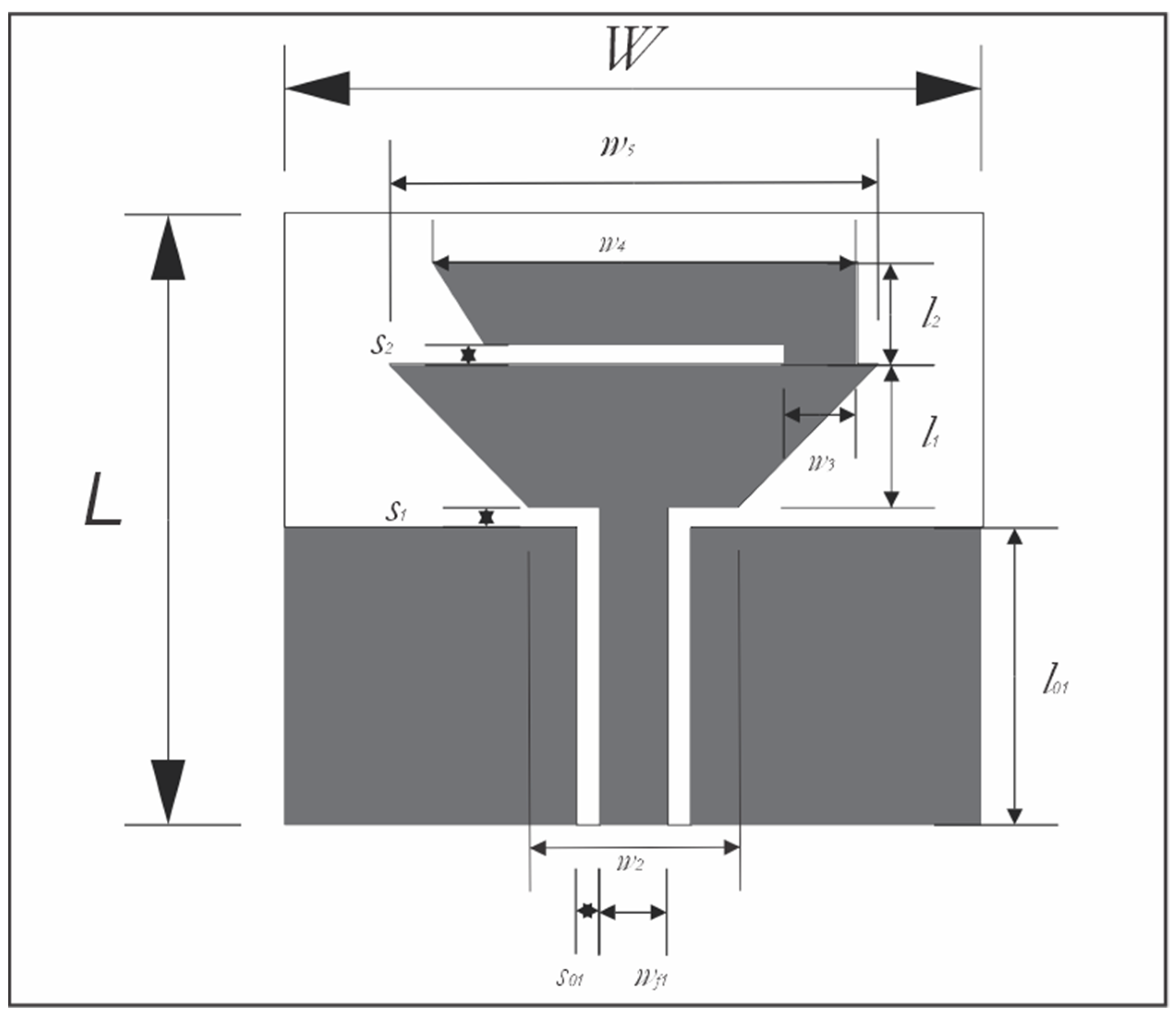
| Parameter | Dimension (mm) | Parameter | Dimension (mm) |
|---|---|---|---|
| L | 30 | l1 | 7 |
| W | 30 | l2 | 5 |
| w4 | 17.5 | l01 | 14.1 |
| w2 | 9 | w5 | 21 |
| wf | 2.91 | w3 | 3.1 |
| S0 | 1 | S1 | 1 |
| S2 | 1 |
| Frequency Range | Fractional Bandwidth | |
|---|---|---|
| Simulated | 2.45 GHz | 4% |
| Measured | 2.6 GHz | 4% |
| Simulated | 4.5 to 7.8 GHz | 53% |
| Measured | 4 to 7 GHz | 54% |
| Frequency (GHz) | Gain (dB) | |
|---|---|---|
| Simulated | 2.45 | 0.38 |
| Measured | 2.6 | −0.2 |
| Simulated | 5.8 | 0.765 |
| Measured | 5.8 | 1 |
Publisher’s Note: MDPI stays neutral with regard to jurisdictional claims in published maps and institutional affiliations. |
© 2022 by the authors. Licensee MDPI, Basel, Switzerland. This article is an open access article distributed under the terms and conditions of the Creative Commons Attribution (CC BY) license (https://creativecommons.org/licenses/by/4.0/).
Share and Cite
Morales-Centla, N.; Torrealba-Melendez, R.; Tamariz-Flores, E.I.; López-López, M.; Arriaga-Arriaga, C.A.; Munoz-Pacheco, J.M.; Gonzalez-Diaz, V.R. Dual-Band CPW Graphene Antenna for Smart Cities and IoT Applications. Sensors 2022, 22, 5634. https://doi.org/10.3390/s22155634
Morales-Centla N, Torrealba-Melendez R, Tamariz-Flores EI, López-López M, Arriaga-Arriaga CA, Munoz-Pacheco JM, Gonzalez-Diaz VR. Dual-Band CPW Graphene Antenna for Smart Cities and IoT Applications. Sensors. 2022; 22(15):5634. https://doi.org/10.3390/s22155634
Chicago/Turabian StyleMorales-Centla, Nathaniel, Richard Torrealba-Melendez, Edna Iliana Tamariz-Flores, Mario López-López, Cesar Augusto Arriaga-Arriaga, Jesus M. Munoz-Pacheco, and Victor R. Gonzalez-Diaz. 2022. "Dual-Band CPW Graphene Antenna for Smart Cities and IoT Applications" Sensors 22, no. 15: 5634. https://doi.org/10.3390/s22155634
APA StyleMorales-Centla, N., Torrealba-Melendez, R., Tamariz-Flores, E. I., López-López, M., Arriaga-Arriaga, C. A., Munoz-Pacheco, J. M., & Gonzalez-Diaz, V. R. (2022). Dual-Band CPW Graphene Antenna for Smart Cities and IoT Applications. Sensors, 22(15), 5634. https://doi.org/10.3390/s22155634