
Dual-Frequency Linear-to-Circular Polarization Converter for Ka-Band Applications


Abstract
:1. Introduction
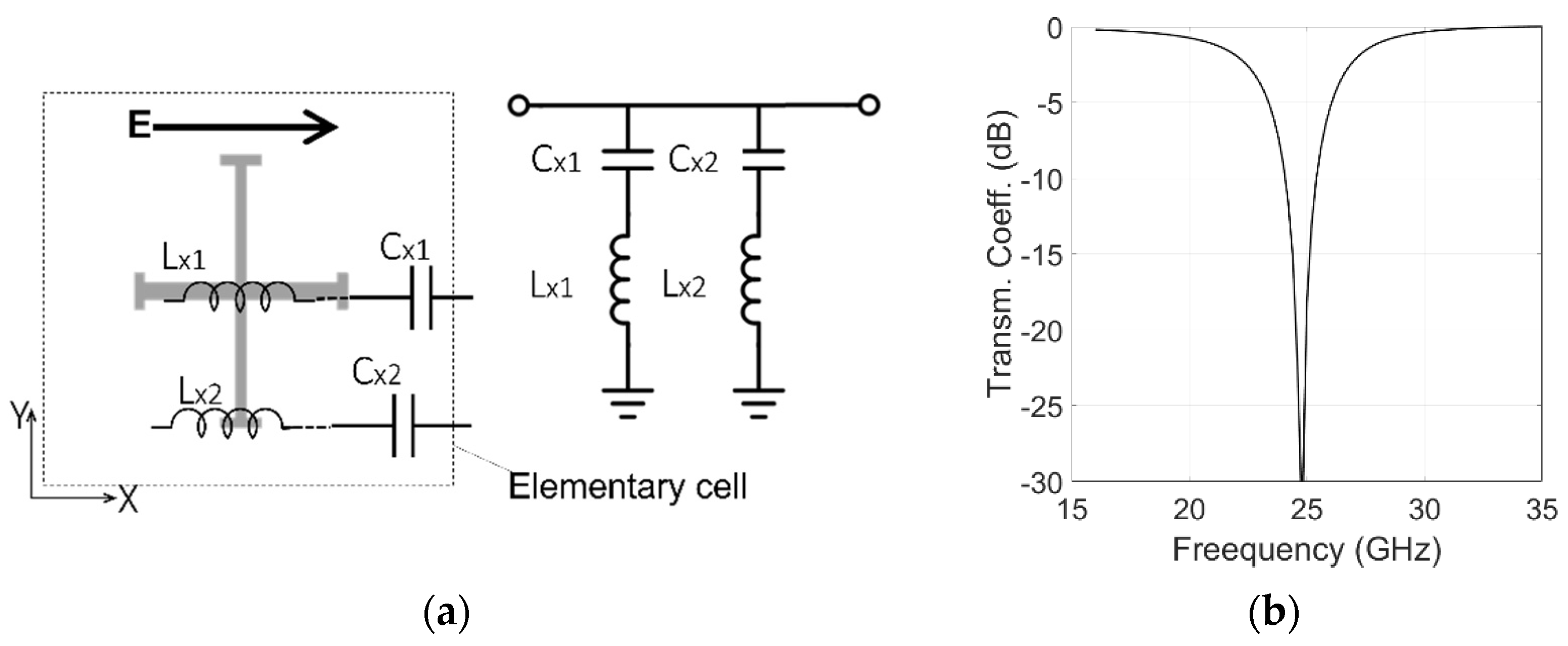
2. Design of the Unit Cell
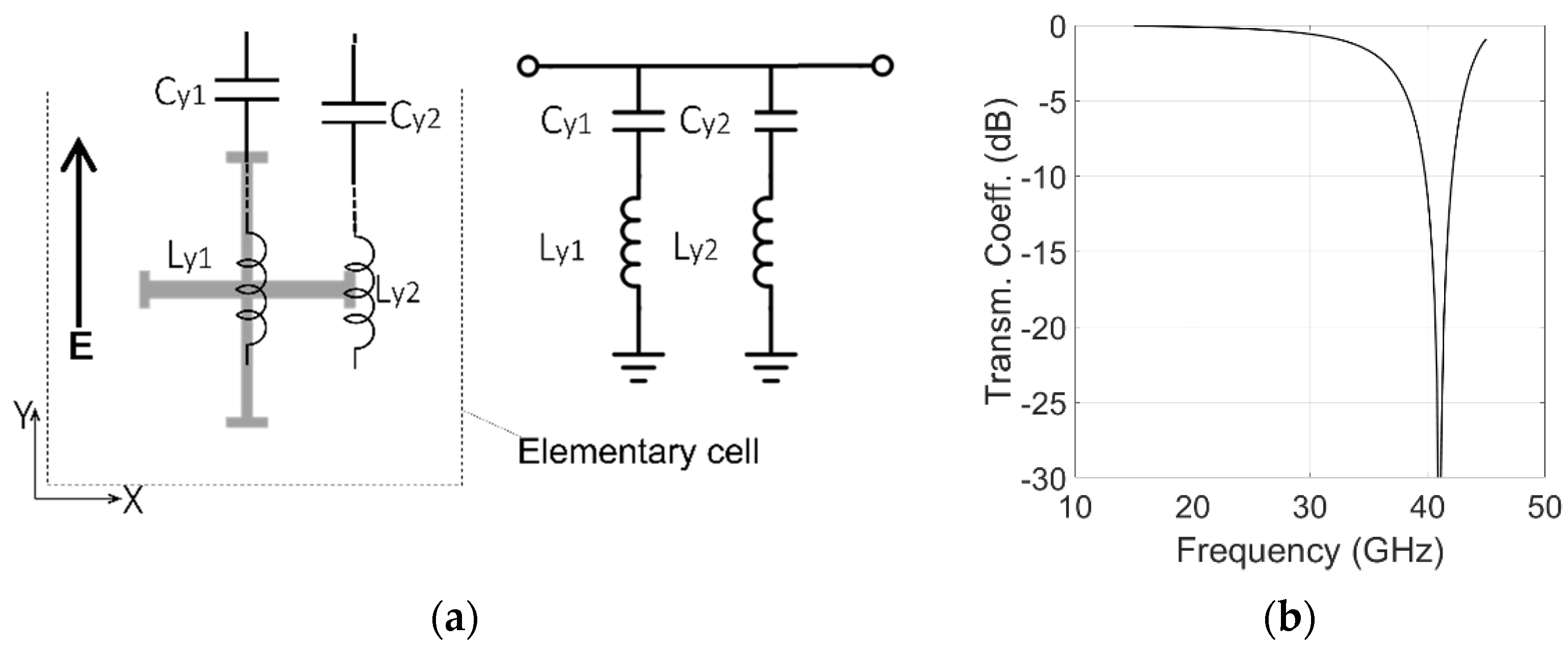
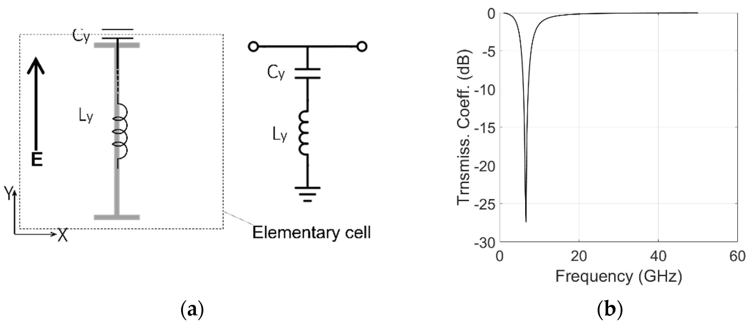
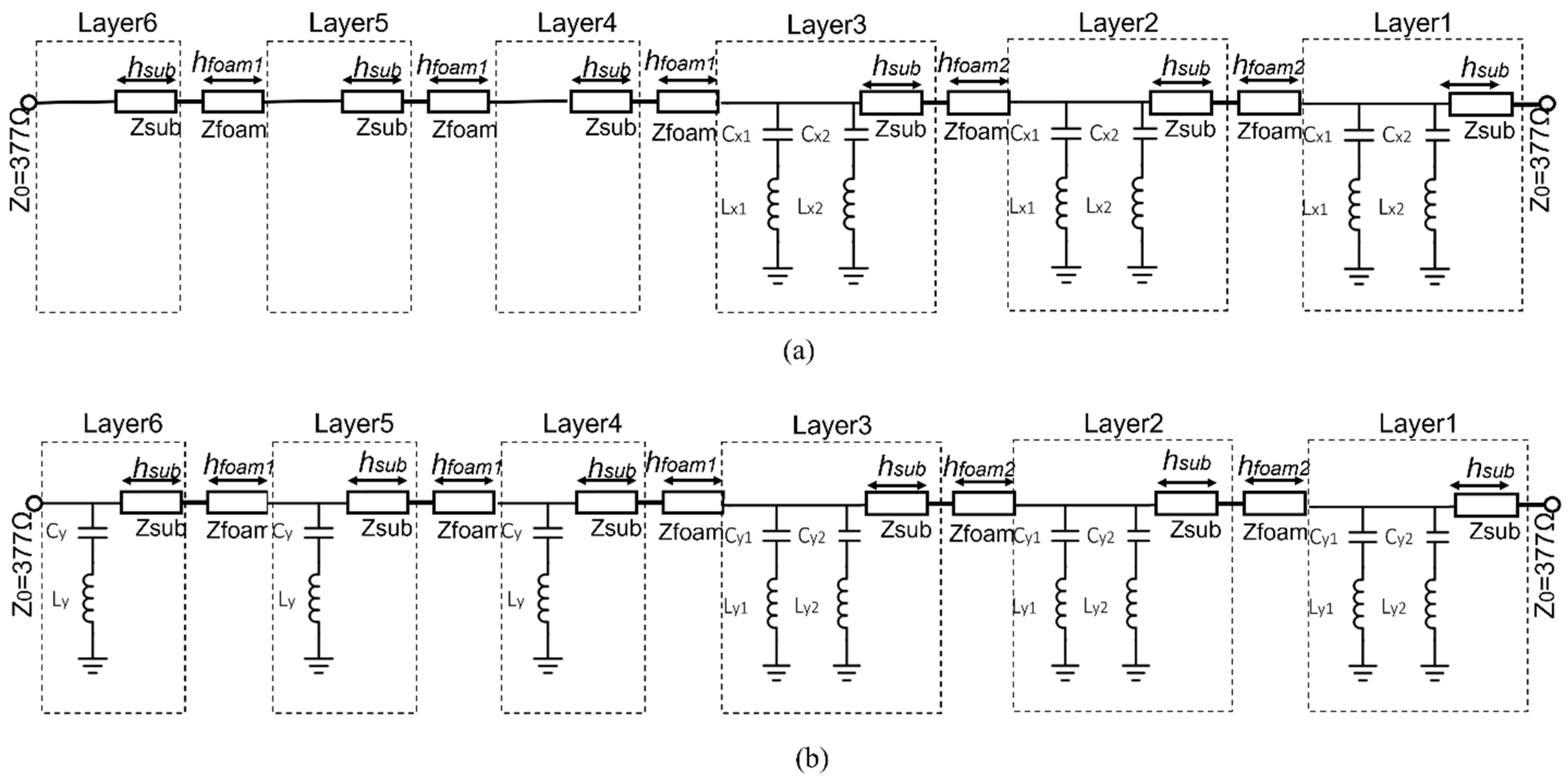
Equivalent Circuit Model
3. Simulated Results
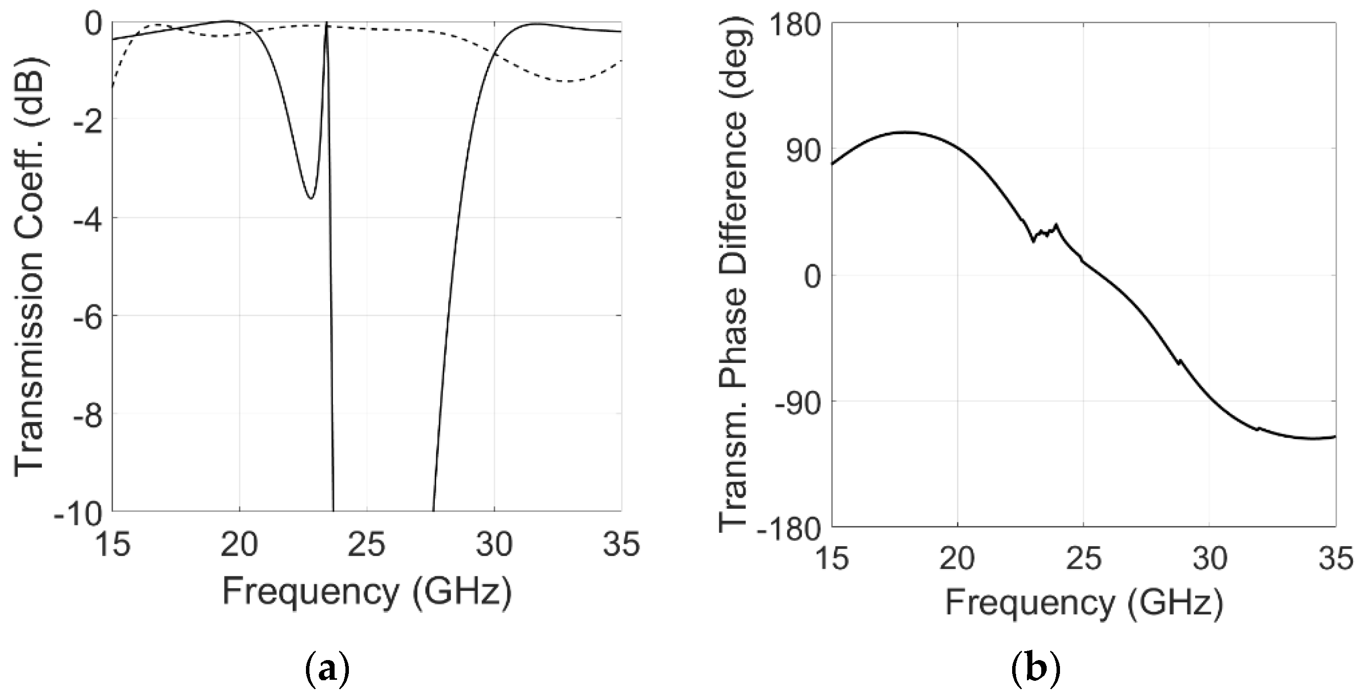
3.1. Equivalent Circuit Simulations
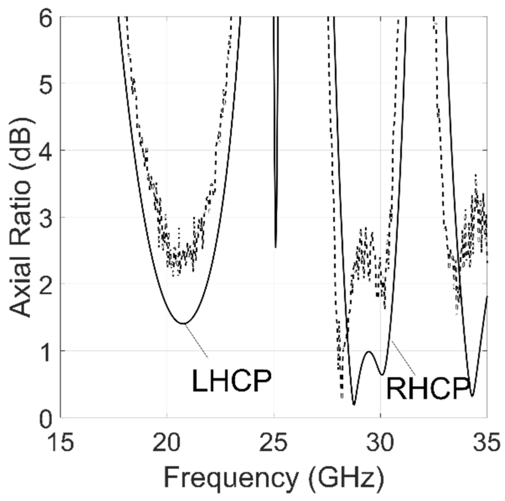
3.2. Full Wave Simulations
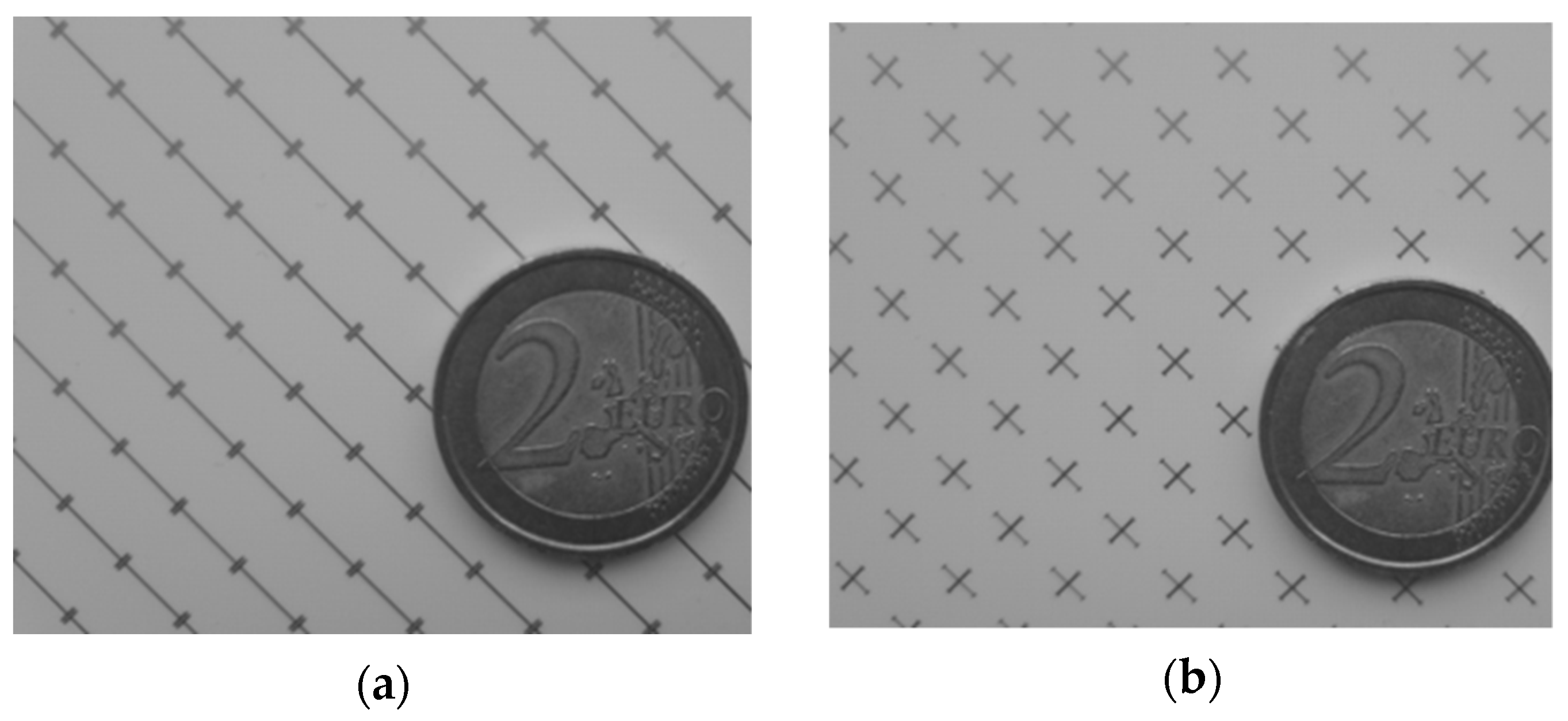
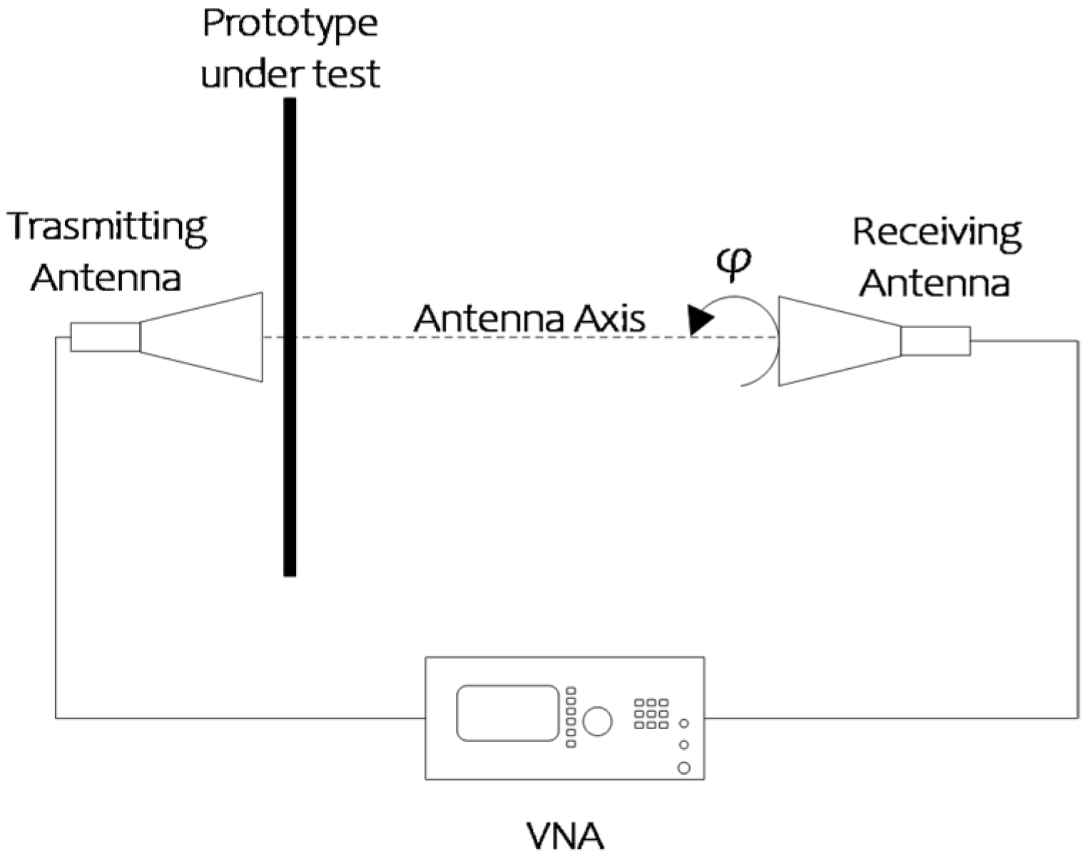
4. Measured Results
5. Conclusions
Author Contributions
Funding
Institutional Review Board Statement
Informed Consent Statement
Data Availability Statement
Conflicts of Interest
References
- Kumar, S.; Lee, G.H.; Kim, D.H.; Choi, H.C.; Kim, K.W. Dual Circularly Polarized Planar Four-Port MIMO Antenna with Wide Axial-Ratio Bandwidth. Sensors 2020, 20, 5610. [Google Scholar] [CrossRef] [PubMed]
- Nalanagula, R.; Darimireddy, N.; Kumari, R.; Park, C.-W.; Reddy, R. Circularly Polarized Hybrid Dielectric Resonator Antennas: A Brief Review and Perspective Analysis. Sensors 2021, 21, 4100. [Google Scholar] [CrossRef] [PubMed]
- Mujahidin, I.; Kitagawa, A. CP Antenna with 2 × 4 Hybrid Coupler for Wireless Sensing and Hybrid RF Solar Energy Harvesting. Sensors 2021, 21, 7721. [Google Scholar] [CrossRef] [PubMed]
- Greco, F.; Amendola, G.; Arnieri, E.; Boccia, L.; Sandhu, A.I. A dual-band, dual-polarized array element for Ka band satcom on the move terminals. In Proceedings of the 8th European Conference on Antennas and Propagation, EuCAP 2014, The Hague, The Netherlands, 6–11 April 2014; pp. 2432–2435. [Google Scholar] [CrossRef]
- Arnieri, E.; Salucci, M.; Greco, F.; Boccia, L.; Massa, A.; Amendola, G. An Equivalent Circuit/System by Design Approach to the Design of Reflection-Type Dual-Band Circular Polarizers. IEEE Trans. Antennas Propag. 2021, 70, 2364–2369. [Google Scholar] [CrossRef]
- Doumanis, E.; Goussetis, G.; Gomez-Tornero, J.L.; Cahill, R.; Fusco, V. Anisotropic Impedance Surfaces for Linear to Circular Polarization Conversion. IEEE Trans. Antennas Propag. 2012, 60, 212–219. [Google Scholar] [CrossRef]
- Gansel, J.K.; Thiel, M.; Rill, M.S.; Decker, M.; Bade, K.; Saile, V.; Von Freymann, G.; Linden, S.; Wegener, M. Gold Helix Photonic Metamaterial as Broadband Circular Polarizer. Science 2009, 325, 1513–1515. [Google Scholar] [CrossRef] [PubMed]
- Yang, W.; Tam, K.W.; Choi, W.-W.; Che, W.; Hui, H.T. Novel Polarization Rotation Technique Based on an Artificial Magnetic Conductor and Its Application in a Low-Profile Circular Polarization Antenna. IEEE Trans. Antennas Propag. 2014, 62, 6206–6216. [Google Scholar] [CrossRef]
- Amitay, N.; Saleh, A. Broad-band wide-angle quasi-optical polarization rotators. IEEE Trans. Antennas Propag. 1983, 31, 73–76. [Google Scholar] [CrossRef]
- Zhang, W.; Li, J.-Y.; Xie, J. A Broadband Circular Polarizer Based on Cross-Shaped Composite Frequency Selective Surfaces. IEEE Trans. Antennas Propag. 2017, 65, 5623–5627. [Google Scholar] [CrossRef]
- Blanco, D.; Sauleau, R. Broadband and Broad-Angle Multilayer Polarizer Based on Hybrid Optimization Algorithm for Low-Cost Ka-Band Applications. IEEE Trans. Antennas Propag. 2018, 66, 1874–1881. [Google Scholar] [CrossRef]
- Arnieri, E.; Greco, F.; Boccia, L.; Amendola, G. A SIW-Based Polarization Rotator With an Application to Linear-to-Circular Dual-Band Polarizers at K-/Ka-Band. IEEE Trans. Antennas Propag. 2020, 68, 3730–3738. [Google Scholar] [CrossRef]
- Naseri, P.; Matos, S.A.; Costa, J.R.; Fernandes, C.A.; Fonseca, N.J.G. Dual-Band Dual-Linear-to-Circular Polarization Converter in Transmission Mode Application to K/Ka -Band Satellite Communications. IEEE Trans. Antennas Propag. 2018, 66, 7128–7137. [Google Scholar] [CrossRef] [Green Version]
- Arnieri, E.; Greco, F.; Amendola, G. A Broadband, Wide-Angle Scanning, Linear-to-Circular Polarization Converter Based on Standard Jerusalem Cross Frequency Selective Surfaces. IEEE Trans. Antennas Propag. 2021, 69, 578–583. [Google Scholar] [CrossRef]
- Abadi, S.M.A.M.H.; Behdad, N. Wideband Linear-to-Circular Polarization Converters Based on Miniaturized-Element Frequency Selective Surfaces. IEEE Trans. Antennas Propag. 2015, 64, 525–534. [Google Scholar] [CrossRef]
- EArnieri, E.; Boccia, L.; Amendola, G. A Ka-Band Dual-Frequency Radiator for Array Applications. IEEE Antennas Wirel. Propag. Lett. 2009, 8, 894–897. [Google Scholar] [CrossRef]
- Xu, H.-X.; Wang, G.-M.; Qi, M.Q.; Cai, T.; Cui, T.J. Compact dual-band circular polarizer using twisted Hilbert-shaped chiral metamaterial. Opt. Express 2013, 21, 24912–24921. [Google Scholar] [CrossRef]
- Mutlu, M.; Akosman, A.E.; Serebryannikov, A.E.; Ozbay, E. Asymmetric chiral metamaterial circular polarizer based on four U-shaped split ring resonators. Opt. Lett. 2011, 36, 1653–16551. [Google Scholar] [CrossRef] [Green Version]
- Bin Wang, H.; Cheng, Y.J. Single-Layer Dual-Band Linear-to-Circular Polarization Converter With Wide Axial Ratio Bandwidth and Different Polarization Modes. IEEE Trans. Antennas Propag. 2019, 67, 4296–4301. [Google Scholar] [CrossRef]
- Yan, S.; VandenBosch, G.A.E. Compact circular polarizer based on chiral twisted double split-ring resonator. Appl. Phys. Lett. 2013, 102, 103503. [Google Scholar] [CrossRef]
- Zeng, Q.; Ren, W.; Zhao, H.; Xue, Z.; Li, W. Dual-band transmission-type circular polariser based on frequency selective surfaces. IET Microw. Antennas Propag. 2019, 13, 216–222. [Google Scholar] [CrossRef]
- Mangi, F.A.; Xiao, S.; Yao, Z.; Memon, I.; Kakepoto, G.F. Dual-band asymmetric circular polariser based on fission transmission of linearly polarised wave. IET Microw. Antennas Propag. 2018, 12, 1414–1419. [Google Scholar] [CrossRef]
- Hosseini, M.; Hum, S.V. A systematic circuit-based approach to efficiently realize single- and dual-band circular polarizers. In Proceedings of the 12th European Conference on Antennas and Propagation (EuCAP 2018), London, UK, 9–13 April 2018; pp. 1–5. [Google Scholar] [CrossRef]
- Arnieri, E.; Greco, F.; Boccia, L.; Amendola, G. A Wide-Angle Scanning Polarization Converter Based on Jerusalem-Cross Frequency Selective Surface. In Proceedings of the 2020 14th European Conference on Antennas and Propagation (EuCAP), Copenhagen, Denmark, 15–20 March 2020; pp. 1–5. [Google Scholar] [CrossRef]
- Hosseini, M.; Hum, S.V. A Circuit-Driven Design Methodology for a Circular Polarizer Based on Modified Jerusalem Cross Grids. IEEE Trans. Antennas Propag. 2017, 65, 5322–5331. [Google Scholar] [CrossRef]
- Wang, H.B.; Cheng, Y.J.; Chen, Z.N. Dual-Band Miniaturized Linear-to-Circular Metasurface Polarization Converter With Wideband and Wide-Angle Axial Ratio. IEEE Trans. Antennas Propag. 2021, 69, 9021–9025. [Google Scholar] [CrossRef]
- Amendola, G.; Angiulli, G.; Arnieri, E.; Boccia, L. Resonant Frequencies of Circular Substrate Integrated Resonators. IEEE Microw. Wirel. Compon. Lett. 2008, 18, 239–241. [Google Scholar] [CrossRef]
- Behdad, N.; Al-Joumayly, M.; Salehi, M. A Low-Profile Third-Order Bandpass Frequency Selective Surface. IEEE Trans. Antennas Propag. 2009, 57, 460–466. [Google Scholar] [CrossRef]
- Al-Joumayly, M.; Behdad, N. A New Technique for Design of Low-Profile, Second-Order, Bandpass Frequency Selective Surfaces. IEEE Trans. Antennas Propag. 2009, 57, 452–459. [Google Scholar] [CrossRef]
- Guo, Q.; Su, J.; Li, Z.; Song, J.; Guan, Y. Miniaturized-Element Frequency-Selective Rasorber Design Using Characteristic Modes Analysis. IEEE Trans. Antennas Propag. 2020, 68, 6683–6694. [Google Scholar] [CrossRef]
- Angiulli, G.; Amendola, G.; Di Massa, G. Application of Characteristic Modes To the Analysis of Scattering From Microstrip Antennas. J. Electromagn. Waves Appl. 2000, 14, 1063–1081. [Google Scholar] [CrossRef]
- Yang, Z.; Warnick, K.F. Analysis and Design of Intrinsically Dual Circular Polarized Microstrip Antennas Using an Equivalent Circuit Model and Jones Matrix Formulation. IEEE Trans. Antennas Propag. 2016, 64, 3858–3868. [Google Scholar] [CrossRef]
- Liu, L.; Korolkiewicz, E.; Ghassemlooy, Z.; Sambell, A.; Danaher, S.; Busawon, K. Investigation of the Equivalent Circuit Parameters and Design of a Dual Polarised Dual Frequency Aperture Coupled Microstrip Antenna. IEEE Trans. Antennas Propag. 2013, 61, 2304–2308. [Google Scholar] [CrossRef] [Green Version]
- Luukkonen, O.; Simovski, C.; Granet, G.; Goussetis, G.; Lioubtchenko, D.; Raisanen, A.V.; Tretyakov, S. Simple and Accurate Analytical Model of Planar Grids and High-Impedance Surfaces Comprising Metal Strips or Patches. IEEE Trans. Antennas Propag. 2008, 56, 1624–1632. [Google Scholar] [CrossRef] [Green Version]
- High Frequency Surface Structure (HFSS). 19th ed. Available online: http://www.ansys.com (accessed on 25 July 2019).
- Wang, D.; Wang, M.; Xu, N.; Wu, W. Improved Measurement Method of Circularly-Polarized Antennas Based on Linear-Component Amplitudes. Open J. Antennas Propag. 2017, 5, 36–45. [Google Scholar] [CrossRef] [Green Version]


| Ref. | Technology | Center Freq. (GHz) | Insertion Loss (dB) | AR Bandwidth | Cell Size | Orthogonal Polarizations |
|---|---|---|---|---|---|---|
| [13] | Patch and a split ring | 19.95, 29.75 | <1, <2 | 5%, 7% | 0.35 λ1 | |
| [20] | Split ring resonators | 8.8, 10.3 | 6 | - | 0.1 λ1 | Yes |
| [22] | Split ring resonators | 15.1, 16.5 | 10, 5 | 11.8%, 6.9% | 0.4 λ1 | No |
| [23] | Modified Jerusalem Cross | 19.6, 29 | 0.6, 0.6 | 4%, 2.7% | - | No |
| [21] | Split ring resonators | 7.6, 13 | 1.5 | 31%, 13.8% | 0.22 λ1 | No |
| [18] | Chiral Metamaterial | 5.1,6.4 | 1.6, 4 | - | 0.26 λ1 | Yes |
| [19] | Jerusalem Cross | 18.5, 29 | 2, 0.8 | 29%, 12% | 0.25 λ1 | Yes |
| [17] | Chiral Metamaterial | 9.77, 11.84 | 1.6, 4 | - | 0.214 λ1 | Yes |
| This Work | Jerusalem Cross/’I’-type strips | 19.95, 29.75 | 0.5, 0.4 | 12.5%, 8.7% | 0.47 λ1 | Yes |
Publisher’s Note: MDPI stays neutral with regard to jurisdictional claims in published maps and institutional affiliations. |
© 2022 by the authors. Licensee MDPI, Basel, Switzerland. This article is an open access article distributed under the terms and conditions of the Creative Commons Attribution (CC BY) license (https://creativecommons.org/licenses/by/4.0/).
Share and Cite
Greco, F.; Arnieri, E. Dual-Frequency Linear-to-Circular Polarization Converter for Ka-Band Applications. Sensors 2022, 22, 2187. https://doi.org/10.3390/s22062187
Greco F, Arnieri E. Dual-Frequency Linear-to-Circular Polarization Converter for Ka-Band Applications. Sensors. 2022; 22(6):2187. https://doi.org/10.3390/s22062187
Chicago/Turabian StyleGreco, Francesco, and Emilio Arnieri. 2022. "Dual-Frequency Linear-to-Circular Polarization Converter for Ka-Band Applications" Sensors 22, no. 6: 2187. https://doi.org/10.3390/s22062187
APA StyleGreco, F., & Arnieri, E. (2022). Dual-Frequency Linear-to-Circular Polarization Converter for Ka-Band Applications. Sensors, 22(6), 2187. https://doi.org/10.3390/s22062187