
Integration of Inertial Sensors in a Lower Limb Robotic Exoskeleton


Abstract
:1. Introduction
2. Materials and Methods
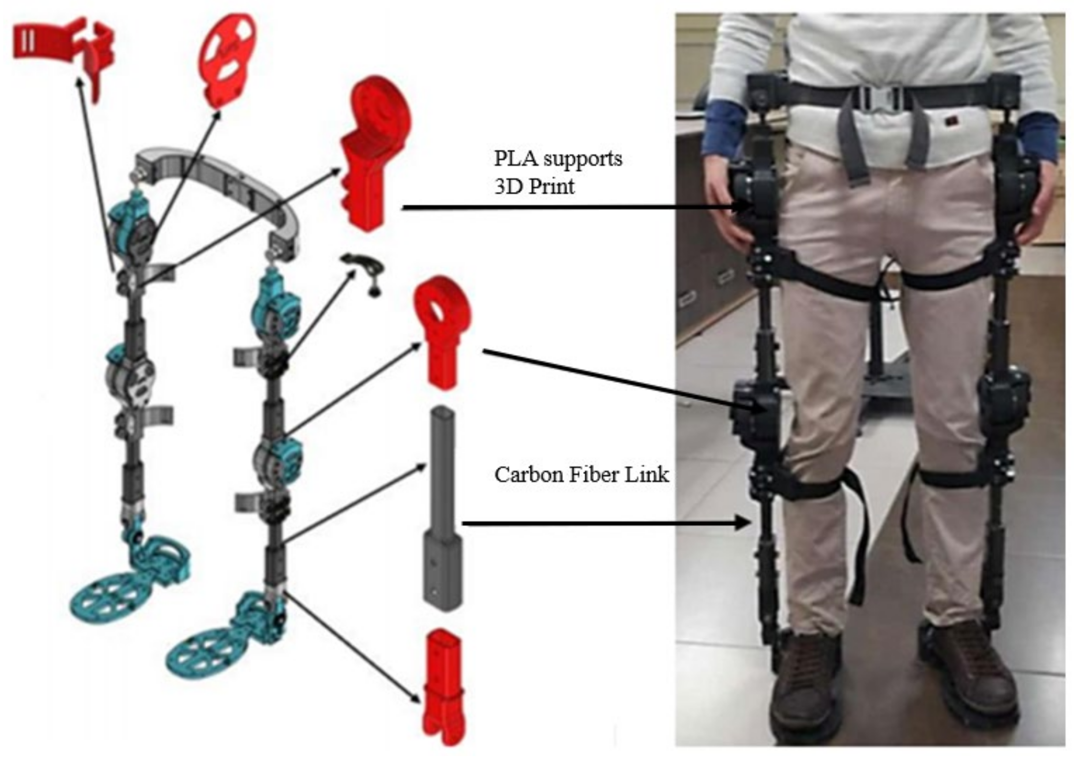
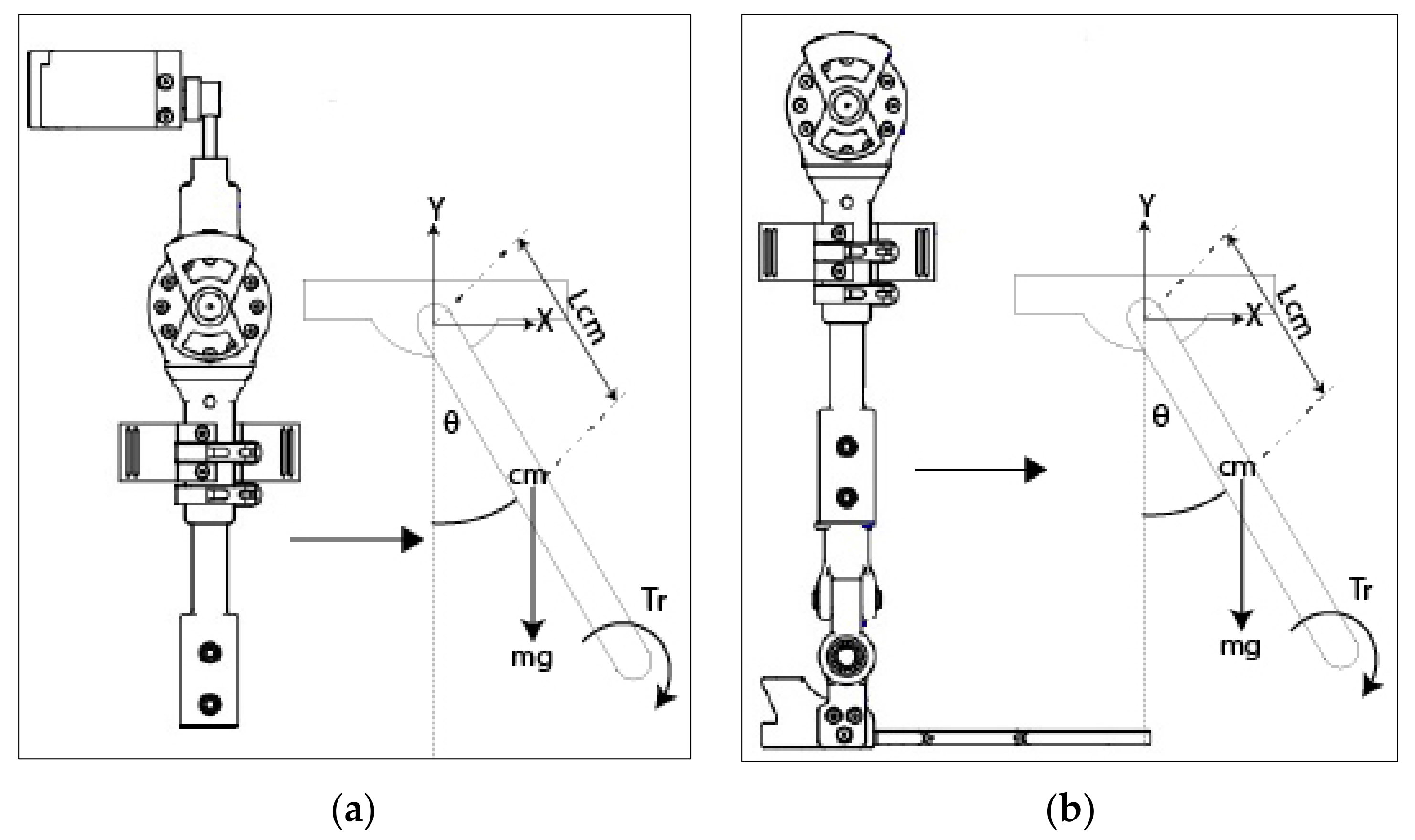
2.1. Exoskeleton Analysis
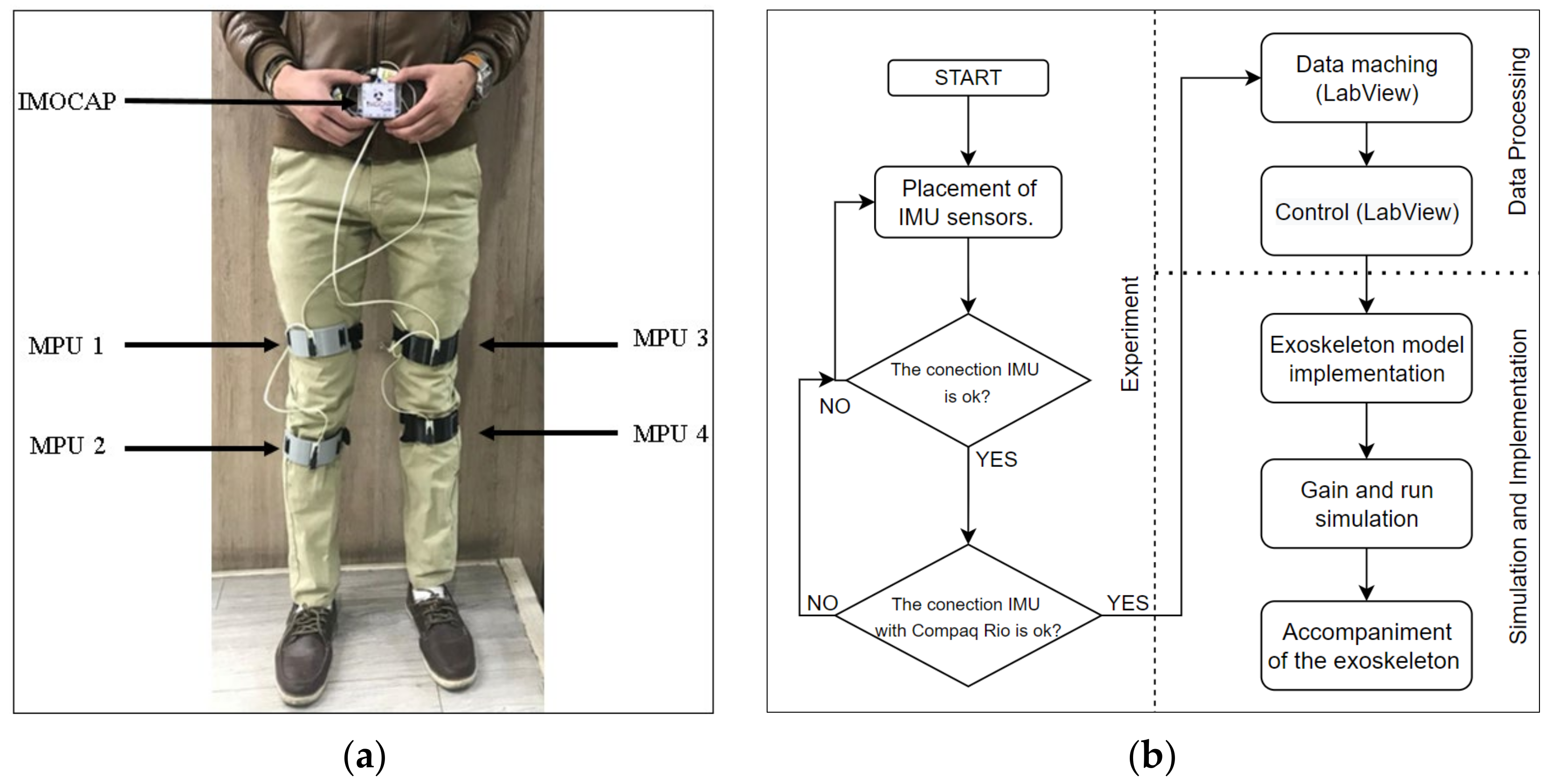
2.2. Imocap-GIS System
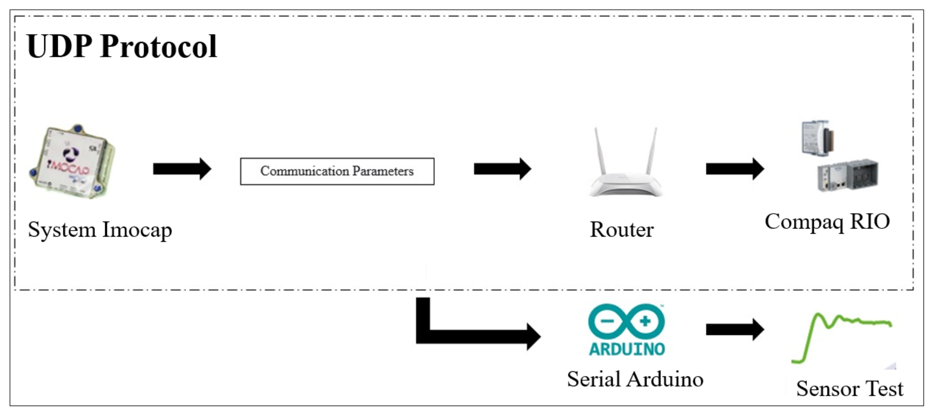
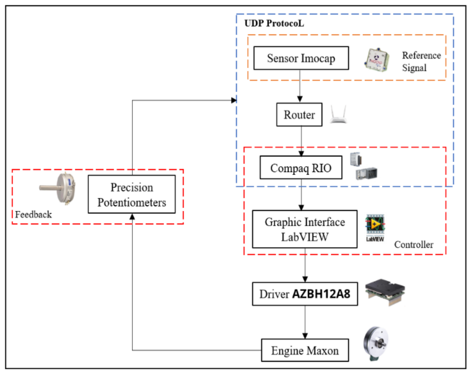
2.3. Integration of the Imocap-GIS System with the Exoskeleton
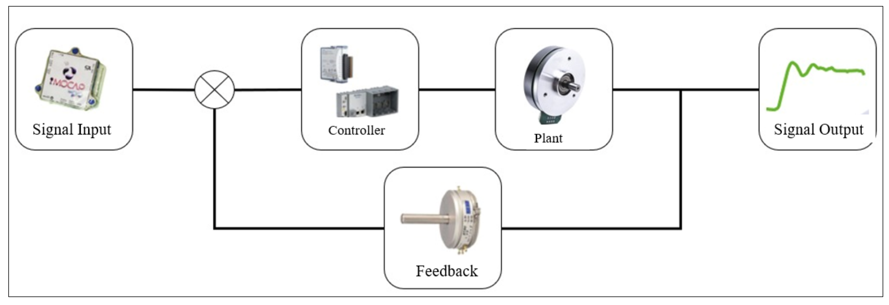
2.3.1. Control System
Obtaining Exoskeleton Equations
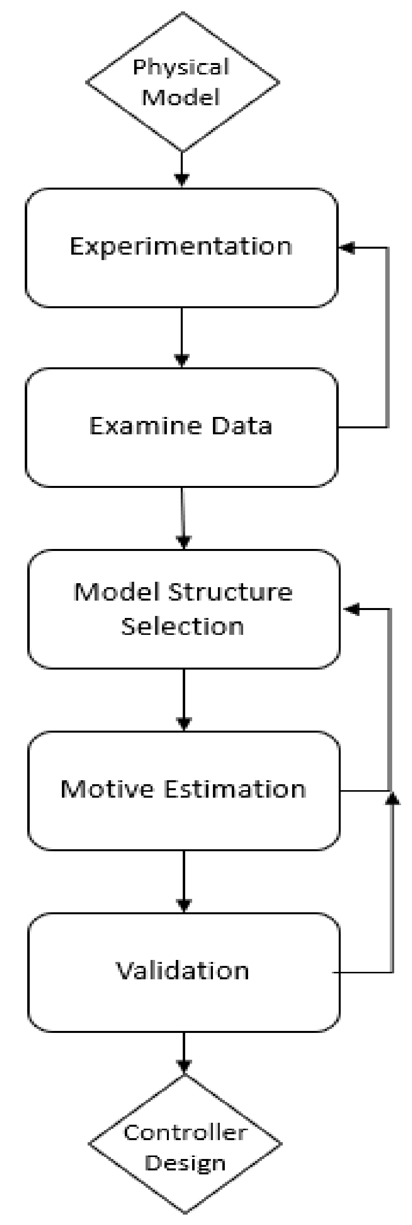
System Identification
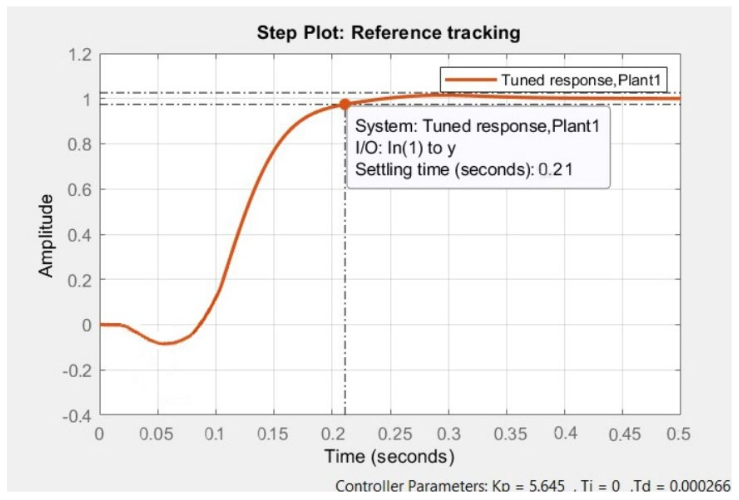
Obtaining the Controller
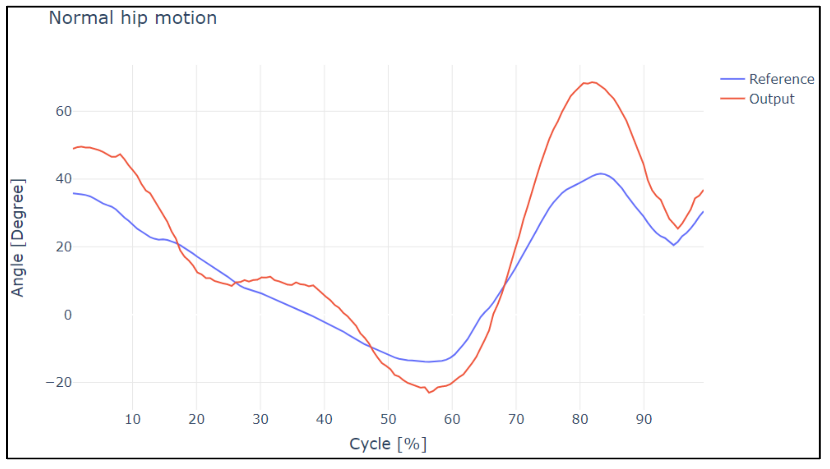
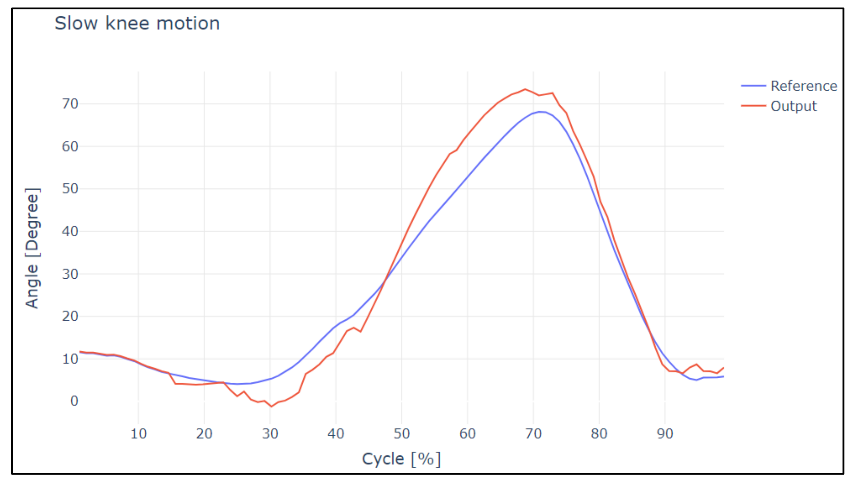
3. Results
4. Discussion
5. Conclusions
Author Contributions
Funding
Institutional Review Board Statement
Informed Consent Statement
Data Availability Statement
Acknowledgments
Conflicts of Interest
Abbreviations
| EEG | (Electroencephalography) |
| EMG | (Electromyography) |
| UDP | (User datagram protocol) |
| SoC | (System-on-Chip) |
| GIIB | (Grupo de Investigación de Ingeniería Biomédica) |
| GIS | (Software Research Group) |
| IMU | (Inertial measurement units) |
| DOF | (Degree of freedom) |
References
- Antwi-Afari, M.F.; Li, H.; Edwards, D.J.; Pärn, E.A.; Seo, J.; Wong, A.Y.L. Biomechanical analysis of risk factors for work-related musculoskeletal disorders during repetitive lifting task in construction workers. Autom. Constr. 2017, 83, 41–47. [Google Scholar] [CrossRef]
- Ma, Y.; Wu, X.; Yang, S.X.; Dang, C.; Liu, D.-X.; Wang, C.; Wang, C.; Chen, C. Online Gait Planning of Lower-Limb Exoskeleton Robot for Paraplegic Rehabilitation Considering Weight Transfer Process. IEEE Trans. Autom. Sci. Eng. 2021, 18, 414–425. [Google Scholar] [CrossRef]
- Sun, Y.; Tang, Y.; Zheng, J.; Dong, D.; Chen, X.; Bai, L. From sensing to control of lower limb exoskeleton: A systematic review. Annu. Rev. Control 2022, 53, 83–96. [Google Scholar] [CrossRef]
- MJuszczak, M.; Gallo, E.; Bushnik, T. Examining the Effects of a Powered Exoskeleton on Quality of Life and Secondary Impairments in People Living with Spinal Cord Injury. Top. Spinal Cord Inj. Rehabil. 2018, 24, 336–342. [Google Scholar] [CrossRef] [PubMed]
- Fournier, B.N.; Lemaire, E.D.; Smith, A.J.J.; Doumit, M. Modeling and Simulation of a Lower Extremity Powered Exoskeleton. IEEE Trans. Neural Syst. Rehabil. Eng. 2018, 26, 1596–1603. [Google Scholar] [CrossRef] [PubMed]
- Plaza, A.; Hernandez, M.; Puyuelo, G.; Garces, E.; Garcia, E. Lower-limb medical and rehabilitation exoskeletons: A review of the current designs. IEEE Rev. Biomed. Eng. 2021, 1–14. [Google Scholar] [CrossRef] [PubMed]
- Sczesny-Kaiser, M.; Kowalewski, R.; Schildhauer, T.; Aach, M.; Jansen, O.; Grasmücke, D.; Güttsches, A.-K.; Vorgerd, M.; Tegenthoff, M. Treadmill Training with HAL Exoskeleton—A Novel Approach for Symptomatic Therapy in Patients with Limb-Girdle Muscular Dystrophy—Preliminary Study. Front. Neurosci. 2017, 11, 449. [Google Scholar] [CrossRef]
- Sanjaya, K.H.; Kusumandari, D.E.; Ristiana, R.; Ambadar, Z.; Utama, D.H.; Shafira, N.S.Z. Design of Lower Limb Exoskeleton for Stroke Patients Gait Rehabilitation. In Proceedings of the 2021 International Conference on Radar, Antenna, Microwave, Electronics, and Telecommunications (ICRAMET), Bandung, Indonesia, 23–24 November 2021; pp. 264–269. [Google Scholar] [CrossRef]
- Feican, C.; Saquicela, C.; Calle-Siguencia, J. Kinematic validation of a lower limb exoeskeleton using computer simulation. In Proceedings of the 2020 IEEE ANDESCON, Quito, Ecuador, 13–16 October 2020; pp. 9–13. [Google Scholar] [CrossRef]
- Liu, D.-X.; Xu, J.; Chen, C.; Long, X.; Tao, D.; Wu, X. Vision-Assisted Autonomous Lower-Limb Exoskeleton Robot. IEEE Trans. Syst. Man Cybern. Syst. 2021, 51, 3759–3770. [Google Scholar] [CrossRef]
- Kilicarslan, A.; Prasad, S.; Grossman, R.G.; Contreras-Vidal, J.L. High accuracy decoding of user intentions using EEG to control a lower-body exoskeleton. In Proceedings of the Annual International Conference of the IEEE Engineering in Medicine and Biology Society, EMBS, Osaka, Japan, 3–7 July 2013; pp. 5606–5609. [Google Scholar] [CrossRef] [Green Version]
- Hasan, S.M.S.; Siddiquee, M.R.; Atri, R.; Ramon, R.; Marquez, J.S.; Bai, O. Prediction of gait intention from pre-movement EEG signals: A feasibility study. J. Neuroeng. Rehabil. 2020, 17, 1–16. [Google Scholar] [CrossRef]
- Harandi, V.J.; Ackland, D.C.; Haddara, R.; Lizama, L.E.C.; Graf, M.; Galea, M.P.; Lee, P.V.S. Gait compensatory mechanisms in unilateral transfemoral amputees. Med. Eng. Phys. 2020, 77, 95–106. [Google Scholar] [CrossRef]
- Gui, K.; Liu, H.; Zhang, D. A Practical and Adaptive Method to Achieve EMG-Based Torque Estimation for a Robotic Exoskeleton. IEEE/ASME Trans. Mechatron. 2019, 24, 483–494. [Google Scholar] [CrossRef]
- Institute of Electrical and Electronics Engineers; IEEE Engineering in Medicine and Biology Society. Signal Contributions in Speed and Slope Estimation Using Robotic Exoskeletons. In Proceedings of the IEEE Robotics and Automation Electromyography (EMG), Toronto, ON, Canada, 24–28 June 2019; pp. 548–553. [CrossRef]
- Głowiński, S.; Ptak, M. A kinematic model of a humanoid lower limb exoskeleton with pneumatic actuators. Acta Bioeng. Biomech. 2022, 24, 2022. [Google Scholar] [CrossRef]
- Vargas-Valencia, L.S.; Elias, A.; Rocon, E.; Bastos-Filho, T.; Frizera, A. An IMU-to-Body Alignment Method Applied to Human Gait Analysis. Sensors 2016, 16, 2090. [Google Scholar] [CrossRef] [Green Version]
- Perry-Rana, S.R.; Housh, T.J.; Johnson, G.O.; Bull, A.J.; Ms, J.M.B.; Cramer, J. MMG and EMG responses during fatiguing isokinetic muscle contractions at different velocities. Muscle Nerve 2002, 26, 367–373. [Google Scholar] [CrossRef]
- Villa-Parra, A.C.; Delisle-Rodriguez, D.; Lima, J.S.; Frizera-Neto, A.; Bastos, T. Knee Impedance Modulation to Control an Active Orthosis Using Insole Sensors. Sensors 2017, 17, 2751. [Google Scholar] [CrossRef] [Green Version]
- Kolaghassi, R.; Al-Hares, M.K.; Sirlantzis, K. Systematic Review of Intelligent Algorithms in Gait Analysis and Prediction for Lower Limb Robotic Systems. IEEE Access 2021, 9, 113788–113812. [Google Scholar] [CrossRef]
- Callejas-Cuervo, M.; Gutierrez, R.M.; Hernandez, A.I. Joint amplitude MEMS based measurement platform for low cost and high accessibility telerehabilitation: Elbow case study. J. Bodyw. Mov. Ther. 2017, 21, 574–581. [Google Scholar] [CrossRef]
- Fukuchi, R.; Fukuchi, C.; Duarte, M. A public dataset of running biomechanics and the effects of running speed on lower extremity kinematics and kinetics. PeerJ 2017, 5, e3298. [Google Scholar] [CrossRef] [Green Version]
- Winter, D.A. Chapter 9: Kinesiological Electromyography. In Biomechanics and Motor Control of Human Movement, 3rd ed.; Winter, D.A., Ed.; John Wiley & Sons, Inc.: Hoboken, NJ, USA, 2005. [Google Scholar] [CrossRef]
- Callejas-Cuervo, M.; Vélez-Guerrero, M.A.; Holguín, W.J.P. Arquitectura de un sistema de medición de bioparámetros integrando señales inerciales-magnéticas y electromiográficas. Rev. Politécnica 2018, 14, 93–102. [Google Scholar] [CrossRef] [Green Version]
- Callejas-Cuervo, M.; Vélez-Guerrero, M.A.; Alarcón-Aldana, A.C. Characterization of Wireless Data Transmission over Wi-Fi in a Biomechanical Information Processing System. Rev. Fac. Ing. 2020, 29, e10228. [Google Scholar] [CrossRef] [Green Version]
- Camargo-Vargas, D.; Callejas-Cuervo, M.; Mazzoleni, S. Brain-Computer Interfaces Systems for Upper and Lower Limb Rehabilitation: A Systematic Review. Sensors 2021, 21, 4312. [Google Scholar] [CrossRef] [PubMed]
- JRecio, S.; Sanchez-Arriaga, G. Mecánica Analítica: Lagrangiana, Hamiltoniana Y Sistemas Dinámicos. Passive Electrodynamic Propulsion for End-of-Life Deorbiting. View Project Simulation and Flight Testing of Power Kites Applied to Wind Energy Generation View Project. 2019. Available online: https://www.researchgate.net/publication/333972497 (accessed on 2 June 2022).
- Liu, D.-X.; Wu, X.; Du, W.; Wang, C.; Xu, T. Gait Phase Recognition for Lower-Limb Exoskeleton with Only Joint Angular Sensors. Sensors 2016, 16, 1579. [Google Scholar] [CrossRef] [PubMed] [Green Version]
- Yi, C.; Zhang, S.; Jiang, F.; Liu, J.; Ding, Z.; Yang, C.; Zhou, H. Enable Fully Customized Assistance: A Novel IMU-based Motor Intent Decoding Scheme. IEEE Trans. Cogn. Dev. Syst. 2021, 1. [Google Scholar] [CrossRef]
- Patzer, I.; Asfour, T. Minimal Sensor Setup in Lower Limb Exoskeletons for Motion Classification based on Multi-Modal Sensor Data. In Proceedings of the IEEE International Conference on Intelligent Robots and Systems, Macau, China, 3–8 November 2019; pp. 8164–8170. [Google Scholar] [CrossRef]
- Kim, J.-H.; Han, J.W.; Kim, D.Y.; Baek, Y.S. Design of a Walking Assistance Lower Limb Exoskeleton for Paraplegic Patients and Hardware Validation Using CoP. Int. J. Adv. Robot. Syst. 2013, 10, 113. [Google Scholar] [CrossRef] [Green Version]


| Analysis | Pearson Coefficient | Concordance Coefficient |
|---|---|---|
| Slow Hip Motion | ||
| Reference values—Output values | 0.9447 | 0.9881 |
| Normal Hip Motion | ||
| Reference values—Output values | 0.8765 | 0.9220 |
| Analysis | Pearson Coefficient | Concordance Coefficient |
|---|---|---|
| Slow Knee Motion | ||
| Reference values—Output values | 0.9532 | 0.9620 |
| Normal Knee Motion | ||
| Reference values—Output values | 0.8721 | 0.9125 |
| Article | Error between Curves | Response Delay | Velocity | Samples |
|---|---|---|---|---|
| This Document | 15.98% | 30 ms | 0.25 to 0.5 m/s | 20 |
| 10.56% | 30 ms | 1 to 1.25 m/s | 20 | |
| Chen | 10.57% | 145.12 ms | 0.75 to 1.5 m/s | 800 |
| Yi | 7.7% | 22.5 ms | 1 to 1.5 m/s | 1000 |
| 13.1% | ||||
| 6.8% | ||||
| Patzer | 7.2% | 638.97 ms | No Information | 500 |
| Kim | No Information | 31.4 ms | 0.8 to 1.5 m/s | 20 |
Publisher’s Note: MDPI stays neutral with regard to jurisdictional claims in published maps and institutional affiliations. |
© 2022 by the authors. Licensee MDPI, Basel, Switzerland. This article is an open access article distributed under the terms and conditions of the Creative Commons Attribution (CC BY) license (https://creativecommons.org/licenses/by/4.0/).
Share and Cite
Calle-Siguencia, J.; Callejas-Cuervo, M.; García-Reino, S. Integration of Inertial Sensors in a Lower Limb Robotic Exoskeleton. Sensors 2022, 22, 4559. https://doi.org/10.3390/s22124559
Calle-Siguencia J, Callejas-Cuervo M, García-Reino S. Integration of Inertial Sensors in a Lower Limb Robotic Exoskeleton. Sensors. 2022; 22(12):4559. https://doi.org/10.3390/s22124559
Chicago/Turabian StyleCalle-Siguencia, John, Mauro Callejas-Cuervo, and Sebastián García-Reino. 2022. "Integration of Inertial Sensors in a Lower Limb Robotic Exoskeleton" Sensors 22, no. 12: 4559. https://doi.org/10.3390/s22124559
APA StyleCalle-Siguencia, J., Callejas-Cuervo, M., & García-Reino, S. (2022). Integration of Inertial Sensors in a Lower Limb Robotic Exoskeleton. Sensors, 22(12), 4559. https://doi.org/10.3390/s22124559