
Collaborative Robotic Wire + Arc Additive Manufacture and Sensor-Enabled In-Process Ultrasonic Non-Destructive Evaluation

 , , , ,
  ,
,
Abstract
:1. Introduction
2. The Architecture of the WAAM + NDE Cell
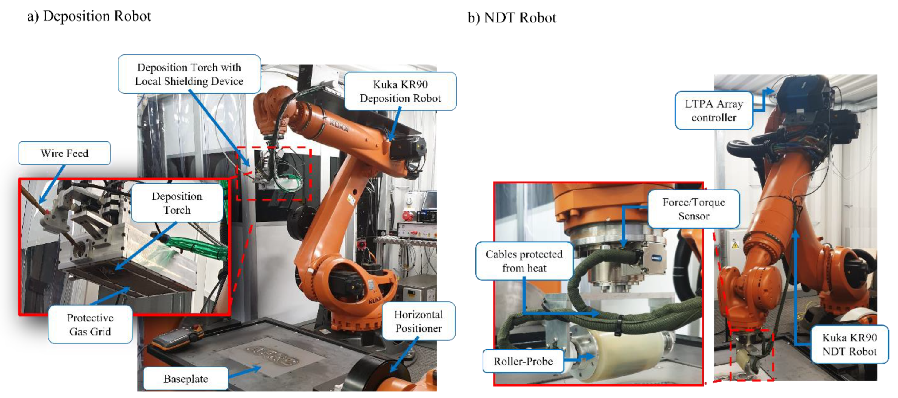
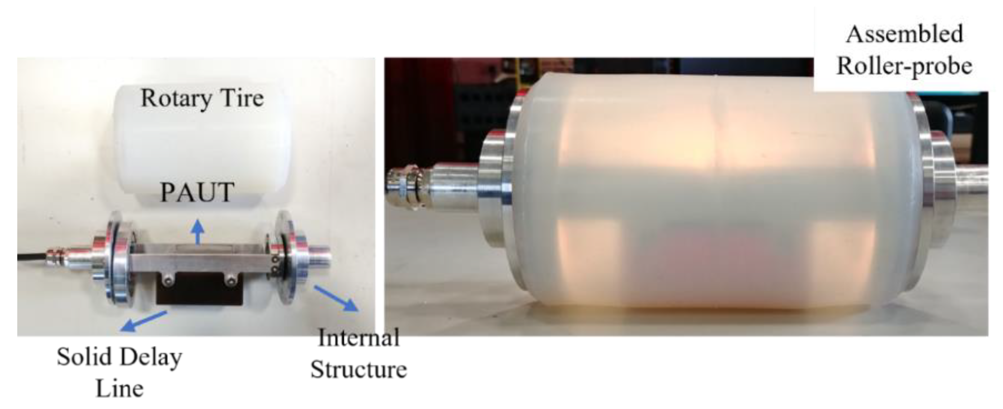
2.1. Hardware
2.2. Software Setup
2.2.1. Deposition
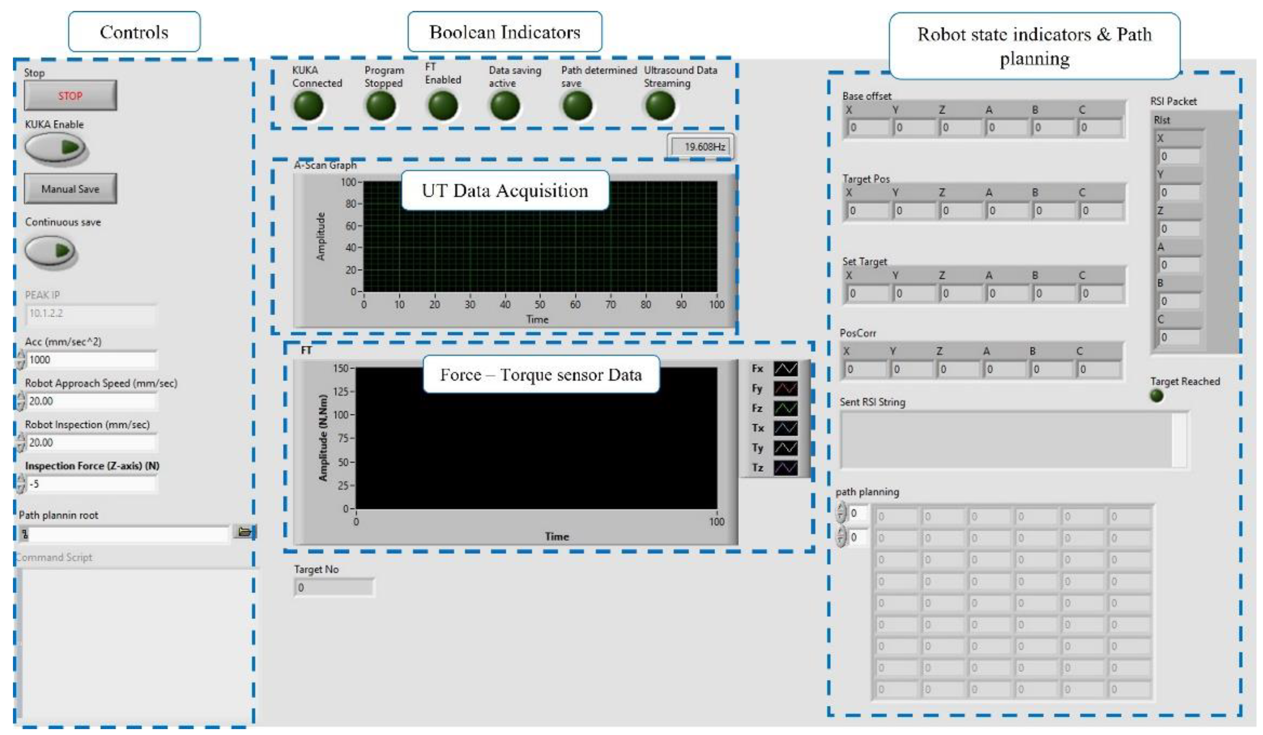
2.2.2. NDE Software
3. Experimental WAAM Manufacturing
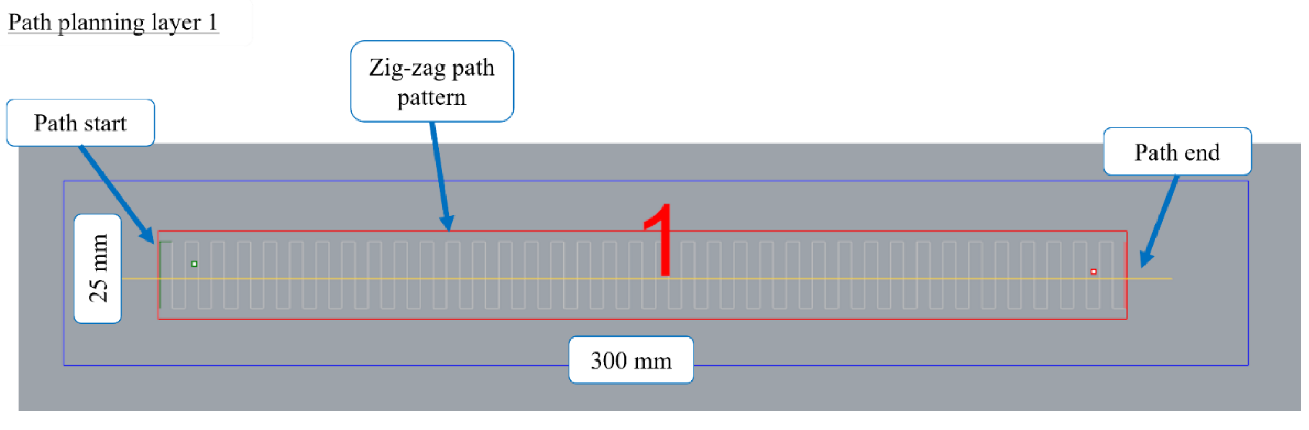
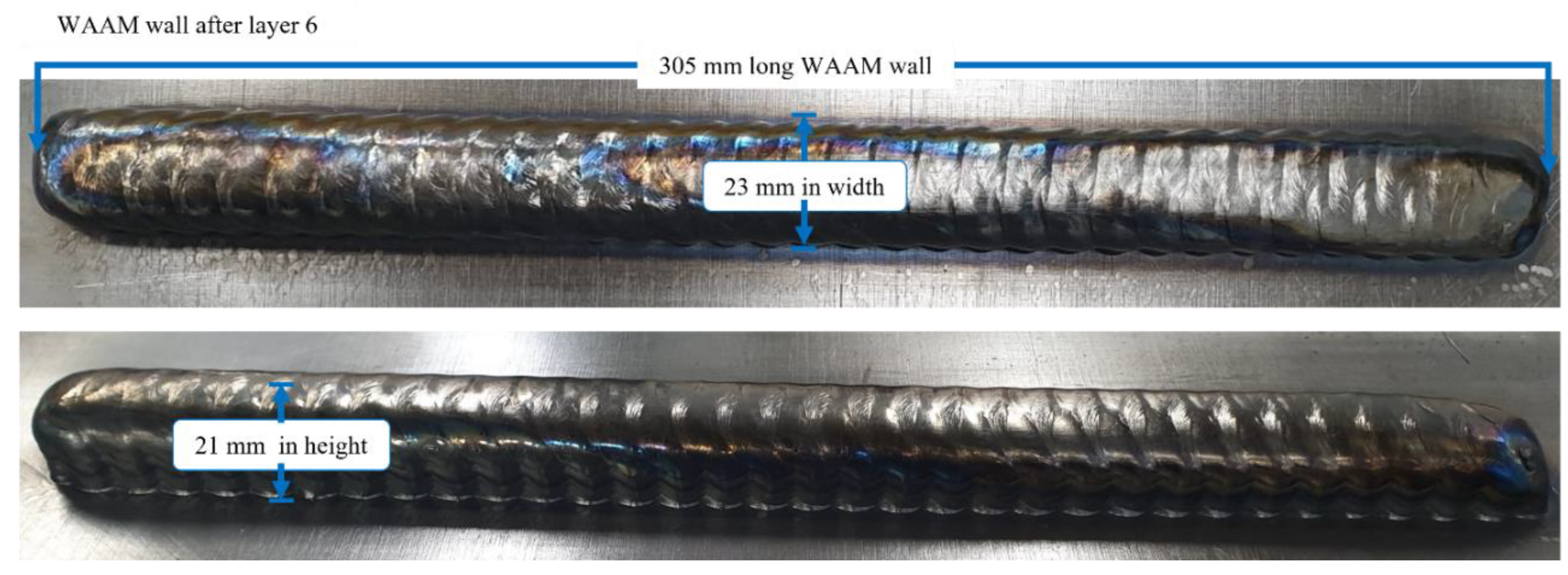
3.1. WAAM Wall Path Planning and Deposition Parameters
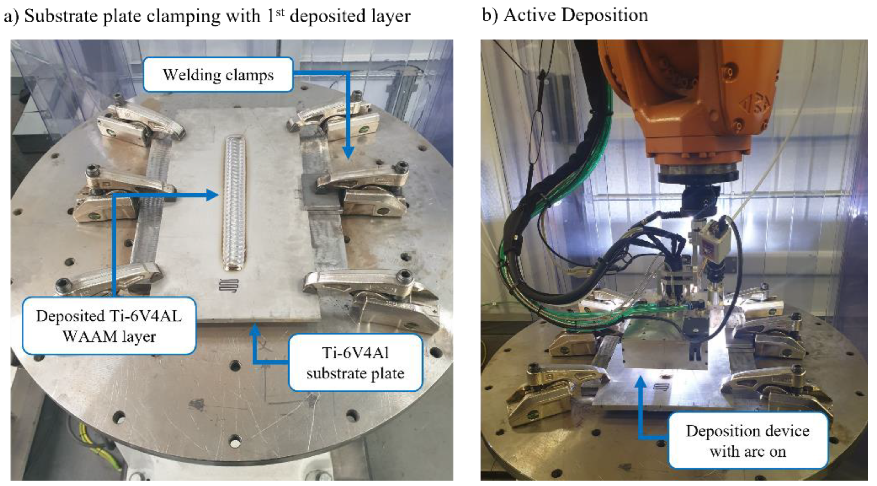
3.2. WAAM Wall Deposition
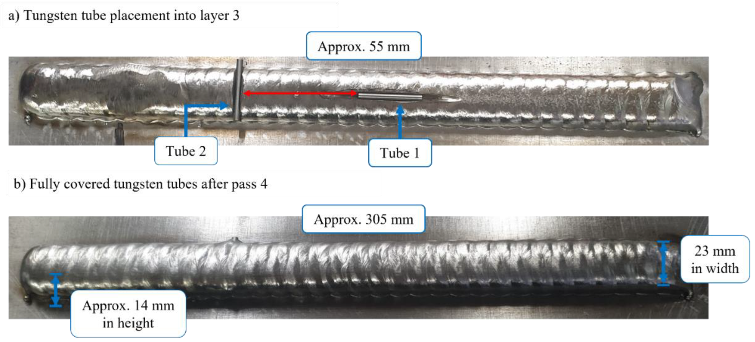
3.3. Ultrasound Reflector Planting
4. In-Process NDE of the Experimental WAAM Wall
4.1. Ultrasound Inspection Parameters
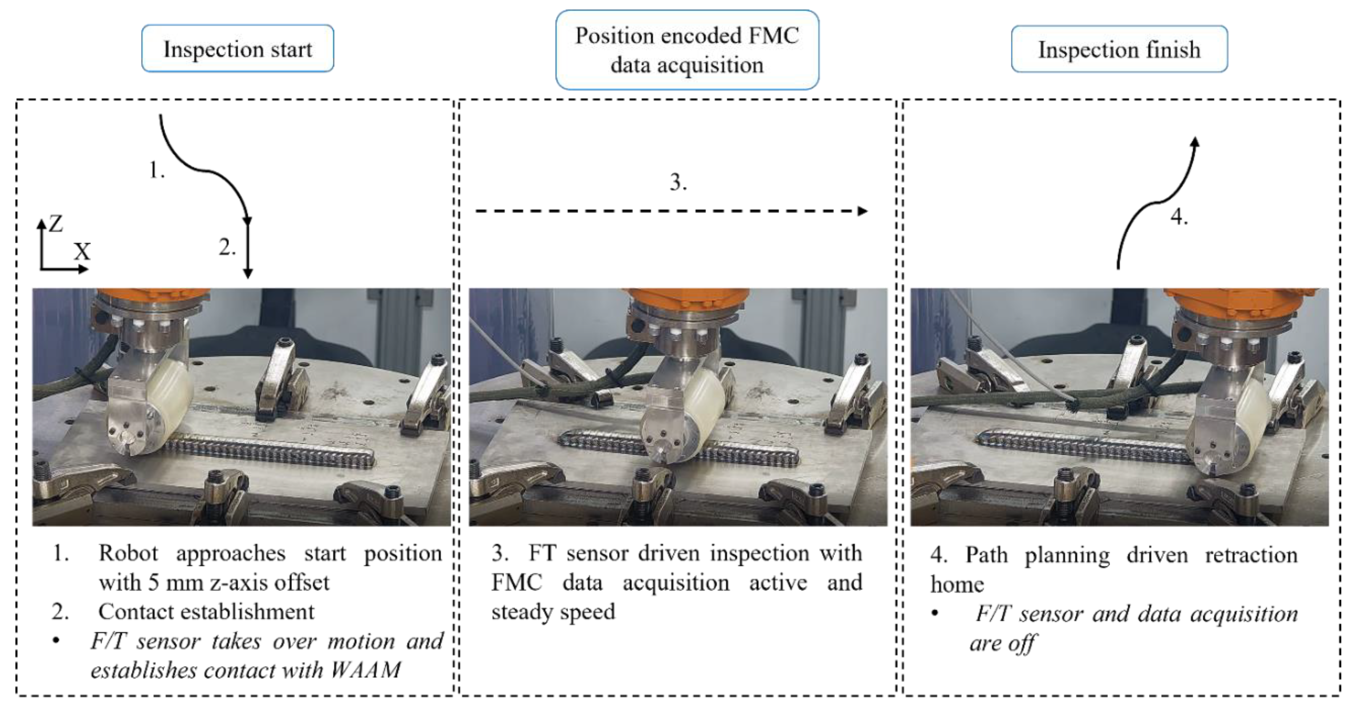
4.2. In-Process NDE
4.3. Ultrasound Data Post-Processing: TFM Imaging and C-Scan
5. In-Process Inspection Results and Discussion
6. Conclusions and Future Work
Author Contributions
Funding
Institutional Review Board Statement
Informed Consent Statement
Data Availability Statement
Acknowledgments
Conflicts of Interest
References
- Metal Additive Manufacture Market. Available online: https://additive-manufacturing-report.com/additive-manufacturing-market/ (accessed on 17 January 2022).
- Zawadzki, P.; Żywicki, K. Smart product design and production control for effective mass customization in the Industry 4.0 concept. Manag. Prod. Eng. Rev. 2016, 7, 105–112. [Google Scholar] [CrossRef]
- DebRoy, T.; Mukherjee, T.; Milewski, J.; Elmer, J.; Ribic, B.; Blecher, J.; Zhang, W. Scientific, technological and economic issues in metal printing and their solutions. Nat. Mater. 2019, 18, 1026–1032. [Google Scholar] [CrossRef] [PubMed]
- Williams, S.W.; Martina, F.; Addison, A.C.; Ding, J.; Pardal, G.; Colegrove, P. Wire+ arc additive manufacturing. Mater. Sci. Technol. 2016, 32, 641–647. [Google Scholar] [CrossRef] [Green Version]
- Wu, B.; Pan, Z.; Ding, D.; Cuiuri, D.; Li, H.; Xu, J.; Norrish, J. A review of the wire arc additive manufacturing of metals: Properties, defects and quality improvement. J. Manuf. Processes 2018, 35, 127–139. [Google Scholar] [CrossRef]
- Thapliyal, S. Challenges associated with the wire arc additive manufacturing (WAAM) of aluminum alloys. Mater. Res. Express 2019, 6, 112006. [Google Scholar] [CrossRef]
- Mohseni, E.; Javadi, Y.; Lines, D.; Vithanage, W.; Kosala, R.; Foster, E.; Qiu, Z.; Zimermann, R.; MacLeod, C.N.; Pierce, S. Ultrasonic phased array inspection of wire plus arc additive manufactured (WAAM) titanium samples. In Proceedings of the 58th Annual British Conference on Non-Destructive Testing, Telford, UK, 3–5 November 2019. [Google Scholar]
- García-Martín, J.; Gómez-Gil, J.; Vázquez-Sánchez, E. Non-destructive techniques based on eddy current testing. Sensors 2011, 11, 2525–2565. [Google Scholar] [CrossRef] [Green Version]
- Lopez, A.; Bacelar, R.; Pires, I.; Santos, T.G.; Sousa, J.P.; Quintino, L. Non-destructive testing application of radiography and ultrasound for wire and arc additive manufacturing. Addit. Manuf. 2018, 21, 298–306. [Google Scholar] [CrossRef]
- Mineo, C.; MacLeod, C.; Morozov, M.; Pierce, S.G.; Lardner, T.; Summan, R.; Powell, J.; McCubbin, P.; McCubbin, C.; Munro, G. Fast ultrasonic phased array inspection of complex geometries delivered through robotic manipulators and high speed data acquisition instrumentation. In Proceedings of the 2016 IEEE International Ultrasonics Symposium (IUS), Tours, France, 18–21 September 2016; pp. 1–4. [Google Scholar]
- Kaczmarek, M.; Piwakowski, B.; Drelich, R. Noncontact ultrasonic nondestructive techniques: State of the art and their use in civil engineering. J. Infrastruct. Syst. 2017, 23, B4016003. [Google Scholar] [CrossRef] [Green Version]
- Javadi, Y.; Sweeney, N.E.; Mohseni, E.; MacLeod, C.N.; Lines, D.; Vasilev, M.; Qiu, Z.; Vithanage, R.K.; Mineo, C.; Stratoudaki, T. In-process calibration of a non-destructive testing system used for in-process inspection of multi-pass welding. Mater. Des. 2020, 195, 108981. [Google Scholar] [CrossRef]
- Javadi, Y.; Mohseni, E.; MacLeod, C.N.; Lines, D.; Vasilev, M.; Mineo, C.; Foster, E.; Pierce, S.G.; Gachagan, A. Continuous monitoring of an intentionally-manufactured crack using an automated welding and in-process inspection system. Mater. Des. 2020, 191, 108655. [Google Scholar] [CrossRef]
- Javadi, Y.; Macleod, C.; Lines, D.; Vasilev, M.; Mohseni, E.; Foster, E.; Qiu, Z.; Vithanage, R.; Zimermann, R.; Loukas, C. In-process inspection of multi-pass robotic welding. In Proceedings of the 46th Annual Review of Progress in Quantitative Nondestructive Evaluation, Portland, OR, USA, 14–18 July 2019. [Google Scholar]
- Vasilev, M.; MacLeod, C.N.; Loukas, C.; Javadi, Y.; Vithanage, R.K.; Lines, D.; Mohseni, E.; Pierce, S.G.; Gachagan, A. Sensor-enabled multi-robot system for automated welding and in-process ultrasonic nde. Sensors 2021, 21, 5077. [Google Scholar] [CrossRef] [PubMed]
- KUKA.RobotSensorInterface 4.0. 2018. Available online: https://www.kuka.com/en-gb/products/robotics-systems/software/system-software/kuka_systemsoftware (accessed on 19 January 2022).
- Vithanage, R.K.; Mohseni, E.; Qiu, Z.; MacLeod, C.; Javadi, Y.; Sweeney, N.; Pierce, G.; Gachagan, A. A phased array ultrasound roller probe for automated in-process/interpass inspection of multipass welds. IEEE Trans. Ind. Electron. 2020, 68, 12781–12790. [Google Scholar] [CrossRef]
- Olympus-ims.com. Ultrasonic Phased Array Wedge for Inspecting High-Temperature Parts up to 150 °C. Available online: https://www.olympus-ims.com/en/applications/ultrasonic-phased-array-wedge-for-inspecting-high-temperature-parts-up-to-150c/#:~:text=As%20phased%20array%20probes%20heat,temperature%20of%2060%20%C2%B0C (accessed on 16 November 2020).
- Mohseni, E.; Vithanage, R.K.W.; Qiu, Z.; MacLeod, C.N.; Javadi, Y.; Lines, D.; Zimermann, R.; Pierce, G.; Gachagan, A.; Ding, J. A high temperature phased array ultrasonic roller probe designed for dry-coupled in-process inspection of wire+ arc additive manufacturing. In Proceedings of the 47th Annual Review of Progress in Quantitative Nondestructive Evaluation, Virtual, 25–26 August 2020. [Google Scholar]
- Lopez, A.B.; Santos, J.; Sousa, J.P.; Santos, T.G.; Quintino, L. Phased Array Ultrasonic Inspection of Metal Additive Manufacturing Parts. J. Nondestruct. Eval. 2019, 38, 62. [Google Scholar] [CrossRef]
- Chauveau, D. Review of NDT and process monitoring techniques usable to produce high-quality parts by welding or additive manufacturing. Weld. World 2018, 62, 1097–1118. [Google Scholar] [CrossRef]
- Zimermann, R.; Mohseni, E.; Lines, D.; Vithanage, R.K.W.; MacLeod, C.N.; Pierce, S.G.; Gachagan, A.; Javadi, Y.; Williams, S.; Ding, J. Multi-Layer Ultrasonic Imaging of As-Built Wire + Arc Additive Manufactured Components. Addit. Manuf. 2021, 48, 102398. [Google Scholar] [CrossRef]
- Holmes, C.; Drinkwater, B.; Wilcox, P. The post-processing of ultrasonic array data using the total focusing method. Insight-Non Destr. Test. Cond. Monit. 2004, 46, 677–680. [Google Scholar] [CrossRef]
- Zimermann, R.; Mohseni, E.; Wathavana Vithanage, R.K.; Lines, D.; MacLeod, C.N.; Pierce, G.; Gachagan, A.; Williams, S.; Ding, J.; Marinelli, G. Implementation of an ultrasonic total focusing method for inspection of unmachined wire + arc additive manufacturing components through multiple interfaces. In Proceedings of the 47th Annual Review of Progress in Quantitative Nondestructive Evaluation, Virtual, 25–26 August 2020. [Google Scholar]
- Javadi, Y.; MacLeod, C.N.; Pierce, S.G.; Gachagan, A.; Lines, D.; Mineo, C.; Ding, J.; Williams, S.; Vasilev, M.; Mohseni, E. Ultrasonic phased array inspection of a Wire+ Arc Additive Manufactured (WAAM) sample with intentionally embedded defects. Addit. Manuf. 2019, 29, 100806. [Google Scholar] [CrossRef]
- Mohseni, E.; Javadi, Y.; Sweeney, N.E.; Lines, D.; MacLeod, C.N.; Vithanage, R.K.; Qiu, Z.; Vasilev, M.; Mineo, C.; Lukacs, P. Model-assisted ultrasonic calibration using intentionally embedded defects for in-process weld inspection. Mater. Des. 2021, 198, 109330. [Google Scholar] [CrossRef]
- Mineo, C.; MacLeod, C.; Morozov, M.; Pierce, S.G.; Summan, R.; Rodden, T.; Kahani, D.; Powell, J.; McCubbin, P.; McCubbin, C. Flexible integration of robotics, ultrasonics and metrology for the inspection of aerospace components. Proc. AIP Conf. Proc. 2017, 1806, 020–026. [Google Scholar]
- Xu, X.; Ding, J.; Ganguly, S.; Diao, C.; Williams, S. Preliminary investigation of building strategies of maraging steel bulk material using wire+ arc additive manufacture. J. Mater. Eng. Perform. 2019, 28, 594–600. [Google Scholar] [CrossRef]
- WAAMctrl. Available online: https://waam3d.com/software/control-suite (accessed on 18 January 2022).
- WAAMPlanner. Available online: https://waam3d.com/software/planner (accessed on 17 January 2022).
- “What is LabVIEW?”. Available online: https://www.ni.com/en-gb/shop/labview.html (accessed on 17 January 2022).
- Aldalur, E.; Veiga, F.; Suárez, A.; Bilbao, J.; Lamikiz, A. High deposition wire arc additive manufacturing of mild steel: Strategies and heat input effect on microstructure and mechanical properties. J. Manuf. Processes 2020, 58, 615–626. [Google Scholar] [CrossRef]
- Colegrove, P.A.; Coules, H.E.; Fairman, J.; Martina, F.; Kashoob, T.; Mamash, H.; Cozzolino, L.D. Microstructure and residual stress improvement in wire and arc additively manufactured parts through high-pressure rolling. J. Mater. Process. Tech. 2013, 213, 1782–1791. [Google Scholar] [CrossRef]
- Javadi, Y.; Akhlaghi, M.; Najafabadi, M.A. Using finite element and ultrasonic method to evaluate welding longitudinal residual stress through the thickness in austenitic stainless steel plates. Mater. Des. 2013, 45, 628–642. [Google Scholar] [CrossRef]
- Vázquez, L.; Rodríguez, N.; Rodríguez, I.; Alberdi, E.; Álvarez, P. Influence of interpass cooling conditions on microstructure and tensile properties of Ti-6Al-4V parts manufactured by WAAM. Weld. World 2020, 64, 1377–1388. [Google Scholar] [CrossRef]
- Lines, D.; Mohseni, E.; Zimermann, R.; Mineo, C.; MacLeod, C.N.; Pierce, G.; Gachagan, A. Modelling of echo amplitude fidelity for transducer bandwidth and TFM pixel resolution. In Proceedings of the 47th Annual Review of Progress in Quantitative Nondestructive Evaluation, Virtual, 25–26 August 2020. [Google Scholar]
- Slongo, J.S.; Gund, J.; Passarin, T.A.R.; Pipa, D.R.; Ramos, J.E.; Arruda, L.V.; Junior, F.N. Effects of Thermal Gradients in High-Temperature Ultrasonic Non-Destructive Tests. Sensors 2022, 22, 2799. [Google Scholar] [CrossRef] [PubMed]


| Deposition Parameters | |
|---|---|
| Current | 150 Amps |
| Wire-feed speed | 2.5 m/min |
| Robot Velocity | 0.005 m/s |
| Tungsten Tube | |
|---|---|
| Tube length | 30 mm |
| Internal diameter | 1 mm |
| Outer diameter | 3 mm |
| Array Parameters | Value |
|---|---|
| Element Count | 64 |
| Element Pitch | 0.5 mm |
| Element Elevation | 10 mm (unfocused) |
| Element Spacing | 0.1 mm |
| Centre Frequency | 5 MHz |
Publisher’s Note: MDPI stays neutral with regard to jurisdictional claims in published maps and institutional affiliations. |
© 2022 by the authors. Licensee MDPI, Basel, Switzerland. This article is an open access article distributed under the terms and conditions of the Creative Commons Attribution (CC BY) license (https://creativecommons.org/licenses/by/4.0/).
Share and Cite
Zimermann, R.; Mohseni, E.; Vasilev, M.; Loukas, C.; Vithanage, R.K.W.; Macleod, C.N.; Lines, D.; Javadi, Y.; Espirindio E Silva, M.P.; Fitzpatrick, S.; et al. Collaborative Robotic Wire + Arc Additive Manufacture and Sensor-Enabled In-Process Ultrasonic Non-Destructive Evaluation. Sensors 2022, 22, 4203. https://doi.org/10.3390/s22114203
Zimermann R, Mohseni E, Vasilev M, Loukas C, Vithanage RKW, Macleod CN, Lines D, Javadi Y, Espirindio E Silva MP, Fitzpatrick S, et al. Collaborative Robotic Wire + Arc Additive Manufacture and Sensor-Enabled In-Process Ultrasonic Non-Destructive Evaluation. Sensors. 2022; 22(11):4203. https://doi.org/10.3390/s22114203
Chicago/Turabian StyleZimermann, Rastislav, Ehsan Mohseni, Momchil Vasilev, Charalampos Loukas, Randika K. W. Vithanage, Charles N. Macleod, David Lines, Yashar Javadi, Misael Pimentel Espirindio E Silva, Stephen Fitzpatrick, and et al. 2022. "Collaborative Robotic Wire + Arc Additive Manufacture and Sensor-Enabled In-Process Ultrasonic Non-Destructive Evaluation" Sensors 22, no. 11: 4203. https://doi.org/10.3390/s22114203
APA StyleZimermann, R., Mohseni, E., Vasilev, M., Loukas, C., Vithanage, R. K. W., Macleod, C. N., Lines, D., Javadi, Y., Espirindio E Silva, M. P., Fitzpatrick, S., Halavage, S., Mckegney, S., Pierce, S. G., Williams, S., & Ding, J. (2022). Collaborative Robotic Wire + Arc Additive Manufacture and Sensor-Enabled In-Process Ultrasonic Non-Destructive Evaluation. Sensors, 22(11), 4203. https://doi.org/10.3390/s22114203