
A Review on Technologies for Localisation and Navigation in Autonomous Railway Maintenance Systems

 ,
,  , ,
, ,
Abstract
:1. Introduction
2. Railway Maintenance Objectives and the Related Techniques
2.1. Maintenance Policy
- Due to the high speed of trains, heavy axle loads, and repetitive loads, the track structure’s strength continues to deteriorate.
- The track structure is subjected to various degrading factors such as rain, sunlight, and wind. The deterioration of rolling stock and rails is unavoidable.
- The track structure has to withstand so many other curvatures, speeds, and load effects, particularly at curves, points, and crossings.
2.1.1. Preventive Maintenance
- Inspection: comparing physical, electrical, mechanical, and other properties (as appropriate) to the expected standards to evaluate the serviceability of materials/items.
- Servicing: cleaning, lubricating, charging, preserving, and so on, of items/materials on a regular basis to avoid incipient breakdowns.
- Calibration: determining the value of an item’s attributes on a regular basis by comparing it to a recognised standard with known accuracy.
- Testing: testing or checking out on a regular basis to verify serviceability and discover electrical/mechanical degradation.
- Alignment: changing the stated variable aspects of an item in order to achieve optimum performance.
- Adjustment: periodically modifying specified material variable parts in order to achieve optimal system performance.
- Installation: regular replacement of limited-life parts or equipment experiencing time cycle or wear degradation to maintain the stated system tolerance.

- Day-to-day maintenance:
- Seasonal Track Maintenance:
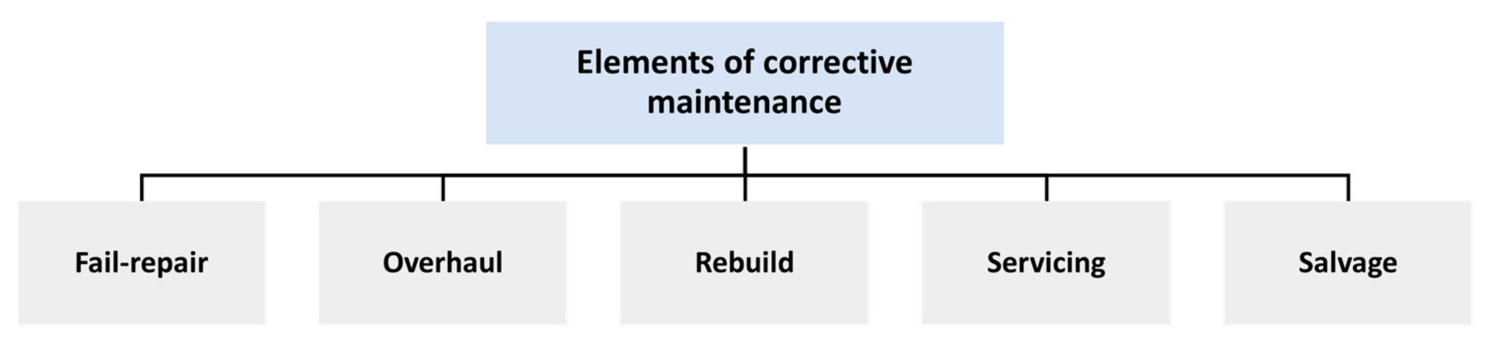
2.1.2. Corrective Maintenance
3. Railway Vehicle Localisation Strategies
- (1)
- Elements in the railway environment (infrastructure-based)
- (2)
- On-board sensors (infrastructure-less)
3.1. Track Infrastructures-Based Strategy
3.2. On-Board Sensors
4. Sensor Hardware
- Tachometers:
- Transponders:
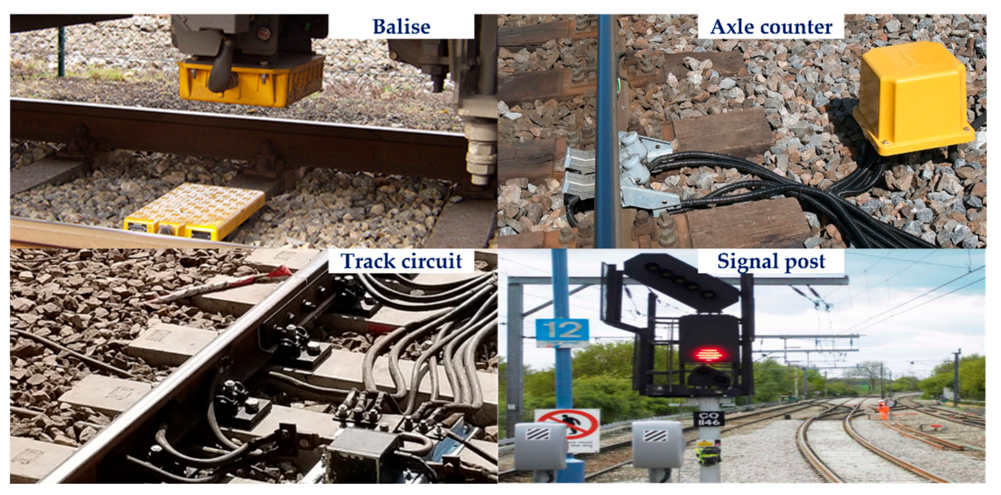
- Balise:
- Doppler Radar:
- Inertial Navigation Systems (INS):
- Global Positioning System (GPS):
- Light Detection and Ranging (LiDAR):
- Visual sensor:
5. Sensor Fusion
5.1. Sensor Fusion Techniques
5.2. Sensor Fusion Algorithms for Vehicle-Based Localisation on the Railway Track
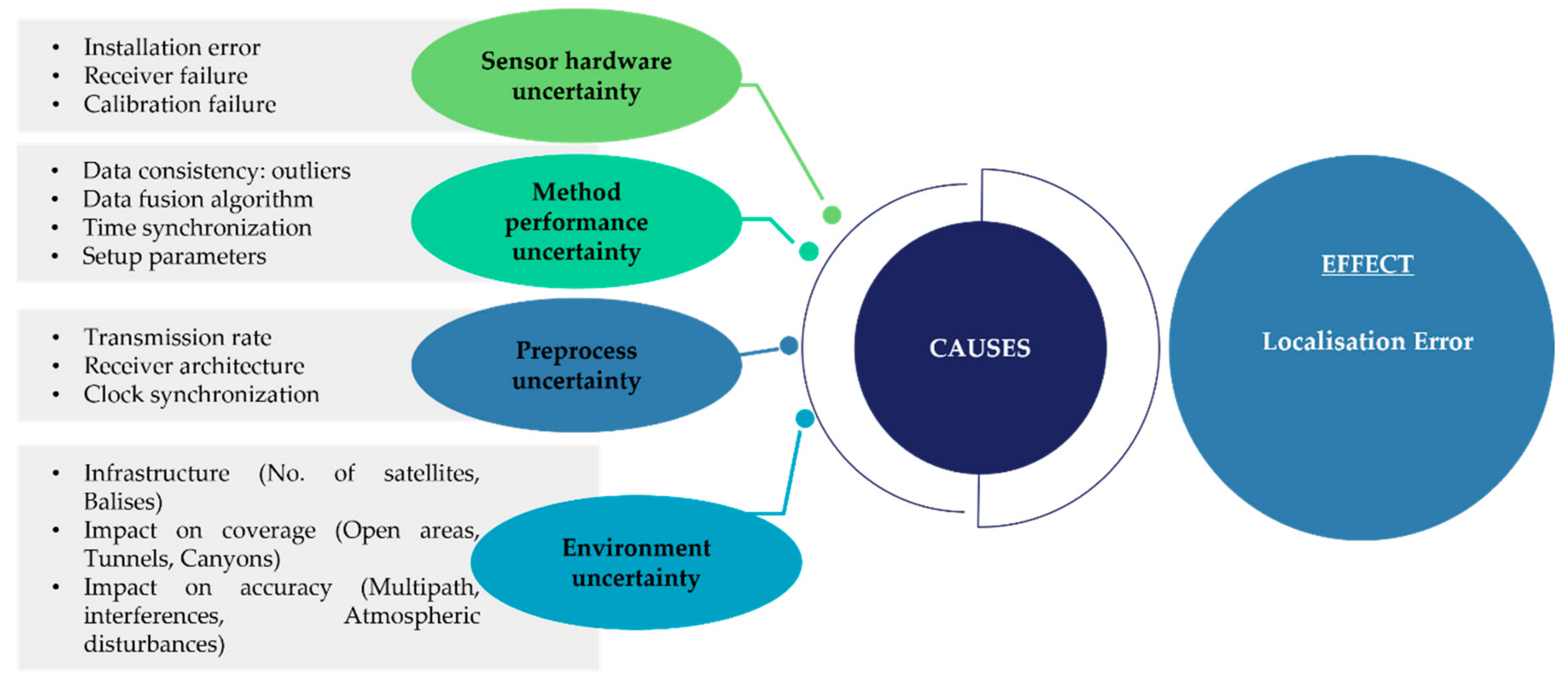
6. Uncertainty in Railway Localisation Performance
- Method performance uncertainty:
- Sensor hardware uncertainty:
- Pre-process uncertainty:
- Environment uncertainty:
7. Conclusions
- First, the railway infrastructure maintenance requirements and strategies, the maintenance objectives, and the general preventive and corrective workflows are reviewed, revealing that accuracy in localisation is essential for autonomous inspection and repair systems.
- Secondly, a review of the most recent and relevant railway vehicle positioning approaches, based on infrastructures in railway environment and on-board sensors, with their principles, advantages and disadvantages were highlighted. It was identified that applying trackside positioning strategy not only lacks efficiency and accuracy for real-time applications, but also requires large civil investment for construction and successive maintenance.
- Next, for obtaining a comprehensive perception for accurate localisation, the sensor fusion techniques and algorithms were discussed to review the applicability of different sensing methods. The most recent fusion approaches based on machine learning were also discussed. It was also mentioned that deep learning fusion approaches are mostly applied in perception, and that further research in pose and depth estimations, loop closure detection, and feature descriptors is needed to achieve maturity in localisation and mapping.
- Furthermore, the uncertainty sources in railway vehicle positioning were discussed to address the challenge features from different sources which impact the localisation accuracy and reliability. Each uncertainty source was separately investigated and the solutions and strategies to mitigate the impact of that source were also provided.
Author Contributions
Funding
Institutional Review Board Statement
Informed Consent Statement
Data Availability Statement
Acknowledgments
Conflicts of Interest
References
- Using Analytics to Get European Rail Maintenance on Track|McKinsey. Available online: https://www.mckinsey.com/industries/public-and-social-sector/our-insights/using-analytics-to-get-european-rail-maintenance-on-track (accessed on 22 April 2022).
- Report from the Eim-Efrtc-Cer Working Group on Market Strategies for Track Maintenance & Renewal Follow up to the Conclusions of Ec Innotrack Project/Wp5. Available online: https://www.cer.be/sites/default/files/publication/2353_7473-11_MARKET_STRATEGY_A4_FINAL.pdf (accessed on 22 April 2022).
- Lidén, T. Railway infrastructure maintenance-A survey of planning problems and conducted research. Transp. Res. Procedia 2015, 10, 574–583. [Google Scholar] [CrossRef] [Green Version]
- Rail Track Maintenance: A Career Explained-Rail Futures. Available online: https://railfutures.co.uk/rail-track-maintenance-a-career-explained/ (accessed on 22 April 2022).
- Cost Benchmarking of Network Rail’s Maintenance and renewals Expenditure Annual Report: Year 2 of control Period 6. 2021. Available online: https://www.orr.gov.uk/sites/default/files/2021-07/cost-benchmarking-of-network-rail-annual-report-year-2-of-cp6.pdf (accessed on 22 April 2022).
- Predictive Maintenance of Rail Infrastructure. Available online: https://www.brunel.ac.uk/research/projects/predictive-maintenance-of-rail-infrastructure (accessed on 22 April 2022).
- Parker, L.E.; Draper, J.V. Robotics applications in maintenance and repair. Handb. Ind. Robot. 1998, 2, 1023–1036. [Google Scholar]
- Mahfuz, N.; Dhali, O.A.; Ahmed, S.; Nigar, M. Autonomous railway crack detector robot for bangladesh: SCANOBOT. In Proceedings of the 2017 IEEE Region 10 Humanitarian Technology Conference (R10-HTC), Dhaka, Bangladesh, 21–23 December 2017; pp. 524–527. [Google Scholar]
- James, J.; Wilson, J.; Jetto, J.; Thomas, A.; Dhahabiya, V.K. Intelligent track cleaning robot. In Proceedings of the 2016 IEEE International Conference on Mechatronics and Automation, Harbin, China, 7–10 August 2016; pp. 332–337. [Google Scholar]
- Dhiyaneswaran, J.; Vimal Raja, M.; Ashok Kumar, B.; Muthu Kumaran, C.B. Design and fabrication of railway track cleaning bot. Mater. Today Proc. 2021, 37, 2677–2680. [Google Scholar] [CrossRef]
- Menendez, E.; Victores, J.G.; Montero, R.; Martínez, S.; Balaguer, C. Tunnel structural inspection and assessment using an autonomous robotic system. Autom. Constr. 2018, 87, 117–126. [Google Scholar] [CrossRef]
- Kitamura, A.; Namekawa, T.; Hiramatsu, K.; Sankai, Y. Operating Manipulator Arm by Robot Suit HAL for Remote In-Cell Equipment Maintenance. Nucl. Technol. 2013, 184, 310–319. [Google Scholar] [CrossRef]
- Errico, S.D. Simulation of a railway asset maintenance robot. Cranfield Univ. 2018, 44, 750111. [Google Scholar]
- Martland, C.D. Analysis of the potential impacts of automation and robotics on locomotive rebuilding; Analysis of the potential impacts of automation and robotics on locomotive rebuilding. IEEE Trans. Eng. Manag. 1987, 34, 92–100. [Google Scholar] [CrossRef]
- Robotics and Industrial AI for Track Maintenance Global Railway Review. Available online: https://www.globalrailwayreview.com/article/114137/robotics-and-industrial-ai-track-maintenance/ (accessed on 22 April 2022).
- Esveld, C. Modern Railway Track, 2th edition. MRT-Productions. 2001. Available online: http://www.esveld.com/Documents/MRT_Selection.pdf (accessed on 22 April 2022).
- Sedghi, M.; Kauppila, O.; Bergquist, B.; Vanhatalo, E.; Kulahci, M. A taxonomy of railway track maintenance planning and scheduling: A review and research trends. Reliab. Eng. Syst. Saf. 2021, 215, 107827. [Google Scholar] [CrossRef]
- The Importance of Rail and Track Maintenance-RWB Group Blog. Available online: https://www.rwbgroup.co.uk/the-importance-of-rail-and-track-maintenance/ (accessed on 22 April 2022).
- Vithanage, R.K.W.; Harrison, C.S.; Desilva, A.K.M. Importance and applications of robotic and autonomous systems (RAS) in railway maintenance sector: A review. Computers 2019, 8, 56. [Google Scholar] [CrossRef] [Green Version]
- Vithanage, R.K.W.; Harrison, C.S.; Desilva, A.K.M.M. Enhance 3D Point Cloud Accuracy Through Supervised Machine Learning for Automated Rolling Stock Maintenance: A Railway Sector Case Study. In Proceedings of the 2018 International Conference on Computing, Electronics & Communications Engineering (iCCECE), Southend, UK, 16–17 August 2018. [Google Scholar]
- Railroad-Track Maintenance|Britannica. Available online: https://www.britannica.com/technology/railroad/Track-maintenance (accessed on 22 April 2022).
- Trivedi, M.M.; Ng, K.C.; Lassiter, N.; Capella, R. New generation of multirobot systems. Proc. IEEE Int. Conf. Syst. Man Cybern. 1998, 4, 3342–3346. [Google Scholar] [CrossRef]
- Rowshandel, H.; Nicholson, G.L.; Davis, C.L.; Roberts, C. An integrated robotic system for automatic detection and characterisation of rolling contact fatigue cracks in rails using an alternating current field measurement sensor. Proc. Inst. Mech. Eng. Part F J. Rail Rapid Transit 2013, 227, 310–321. [Google Scholar] [CrossRef]
- Rowshandel, H. The Development of an Autonomous robotic Inspection System to Detect and Characterise Rolling Contact Fatigue Cracks in Railway Track. Available online: http://etheses.bham.ac.uk/4821/ (accessed on 22 April 2022).
- Autonomous Inspection Trolley for Better Train Track Maintenance|AutoScan Project|Results in Brief|H2020|CORDIS|European Commission. Available online: https://cordis.europa.eu/article/id/250858-autonomous-inspection-trolley-for-better-train-track-maintenance (accessed on 22 April 2022).
- Our Platform–RailPod, Inc. Available online: https://rail-pod.com/?page_id=2527 (accessed on 22 April 2022).
- Yunus, S.; Mehmet, K.; Erhan, A. Condition Monitoring Approach Using 3DModelling of Railway Tracks with Laser Cameras. Conference: International Conference on Advanced Technology & Sciences (ICAT’16). Available online: http://www.icatsconf.org/uploads/files2/procedings_v4.pdf (accessed on 22 April 2022).
- Madejski, J. Autonomous track geometry diagnostics system. J. Mater. Process. Technol. 2004, 157–158, 194–202. [Google Scholar] [CrossRef] [Green Version]
- Wang, L.; Zhang, B.; Wu, J.; Xu, H.; Chen, X.; Na, W. Computer vision system for detecting the loss of rail fastening nuts based on kernel two-dimensional principal component–two-dimensional principal component analysis and a support vector machine. Proc. Inst. Mech. Eng. Part F J. Rail Rapid Transit 2015, 230, 1842–1850. [Google Scholar] [CrossRef]
- Gibert, X.; Patel, V.M.; Chellappa, R. Robust fastener detection for autonomous visual railway track inspection. In Proceedings of the 2015 IEEE Winter Conference on Applications of Computer Vision, Waikoloa, HI, USA, 5–9 January 2015. [Google Scholar]
- Al-Douri, Y.K.; Tretten, P.; Karim, R. Improvement of railway performance: A study of Swedish railway infrastructure. J. Mod. Transp. 2016, 24, 22–37. [Google Scholar] [CrossRef] [Green Version]
- Track-Network Rail. Available online: https://www.networkrail.co.uk/running-the-railway/looking-after-the-railway/track/ (accessed on 22 April 2022).
- Dhillon, B.S. Engineering Maintenance: A Modern Approach; CRC Press: Boca Raton, FL, USA, 2002; ISBN 9781420031843. [Google Scholar]
- Shang, H.; Bérenguer, C.; Andrews, J. Delayed maintenance modelling considering speed restriction for a railway section. Proc. Inst. Mech. Eng. Part O J. Risk Reliab. 2017, 231, 411–428. [Google Scholar] [CrossRef] [Green Version]
- Sharma, S.; Cui, Y.; He, Q.; Mohammadi, R.; Li, Z. Data-driven optimization of railway maintenance for track geometry. Transp. Res. Part C Emerg. Technol. 2018, 90, 34–58. [Google Scholar] [CrossRef]
- Comino, F. Cobots for Maintenance in the Railway Industry; Cranfield University: Cranfield, UK, 2018. [Google Scholar]
- Track Treatment Fleet-Network Rail. Available online: https://www.networkrail.co.uk/running-the-railway/looking-after-the-railway/our-fleet-machines-and-vehicles/track-treatment-fleet/ (accessed on 22 April 2022).
- Cannon, D.F.; Edel, K.O.; Grassie, S.L.; Sawley, K. Rail defects: An overview. Fatigue Fract. Eng. Mater. Struct. 2003, 26, 865–886. [Google Scholar] [CrossRef]
- Seasonal Track Treatment and Weather Support Fleet-Network Rail. Available online: https://www.networkrail.co.uk/running-the-railway/looking-after-the-railway/our-fleet-machines-and-vehicles/seasonal-track-treatment-and-weather-support-fleet/ (accessed on 22 April 2022).
- High Output machines-Network Rail. Available online: https://www.networkrail.co.uk/running-the-railway/looking-after-the-railway/our-fleet-machines-and-vehicles/high-output/high-output-machines/ (accessed on 22 April 2022).
- Heirich, O. Localization of Trains and Mapping of Railway Tracks. Ph.D. Thesis, Technische Universität München, München, Germany, 2020. [Google Scholar]
- Requirements for Safety Relevant Positioning Applications in Rail Traffic–A Demonstrator for a Train Borne Navigation Platform Called ‘DemoOrt’. Available online: https://www.researchgate.net/publication/224797887_Requirements_for_Safety_Relevant_Positioning_Applications_in_Rail_Traffic_-_A_Demonstrator_for_a_Train_Borne_Navigation_Platform_Called_DemoOrt (accessed on 22 April 2022).
- Albrecht, T.; Lüddecke, K.; Zimmermann, J. A precise and reliable train positioning system and its use for automation of train operation. In Proceedings of the 2013 IEEE International Conference on Intelligent Rail Transportation Proceedings, Beijing, China, 30 August–1 September 2013. [Google Scholar]
- Lauer, M.; Stein, D. A Train Localization Algorithm for Train Protection Systems of the Future. IEEE Trans. Intell. Transp. Syst. 2015, 16, 970–979. [Google Scholar] [CrossRef]
- Hutchinson, M.; Marais, J.; Masson, E.; Mendizabal, J.; Meyer, M.; Hutchinson, M.; Marais, J.; Masson, E.; Mendizabal, J.; Meyer, M. Precise and reliable localization as a core of railway automation (Rail 4.0). International Congress on High-Speed Rail: Technologies and long Term Impacts. 2017. Available online: https://hal.archives-ouvertes.fr/hal-01662758 (accessed on 22 April 2022).
- European Railway Agency. Railway Safety Performance in the European Union 2008. 2008, Volume 44. Available online: https://www.era.europa.eu/sites/default/files/library/docs/safety_interoperability_progress_reports/railway_safety_performance_2016_en.pdf (accessed on 22 April 2022).
- Temple, W.G.; Anh Tran, B.N.; Chen, B.; Kalbarczyk, Z.; Sanders, W.H. On Train Automatic Stop Control Using Balises: Attacks and a Software-Only Countermeasure. In Proceedings of the 2017 IEEE 22nd Pacific Rim International Symposium on Dependable Computing (PRDC), Christchurch, New Zealand, 22–25 January 2017. [Google Scholar] [CrossRef]
- Zhou, J.; Xiao, H.; Jiang, W.; Bai, W.; Liu, G. Automatic subway tunnel displacement monitoring using robotic total station. Meas. J. Int. Meas. Confed. 2020, 151, 107251. [Google Scholar] [CrossRef]
- Otegui, J.; Bahillo, A.; Lopetegi, I.; Diez, L.E. A Survey of Train Positioning Solutions. IEEE Sens. J. 2017, 17, 6788–6797. [Google Scholar] [CrossRef]
- Heirich, O.; Siebler, B.; Sand, S.; Lehner, A.; Crespillo, O.G. Measurement methods for train localization with onboard sensors. In Proceedings of the 2020 European Navigation Conference (ENC), Dresden, Germany, 23–24 November 2020. [Google Scholar]
- Fouque, C.; Bonnifait, P. Matching raw GPS measurements on a navigable map without computing a global position. IEEE Trans. Intell. Transp. Syst. 2012, 13, 887–898. [Google Scholar] [CrossRef] [Green Version]
- Marais, J.; Beugin, J.; Berbineau, M. A Survey of GNSS-Based Research and Developments for the European Railway Signaling. IEEE Trans. Intell. Transp. Syst. 2017, 18, 2602–2618. [Google Scholar] [CrossRef] [Green Version]
- Hynek, M. Galileo as an Instrument of Unification Galileo as an Instrument of Unification of the European Railway Transport of the European Railway Transport. Railway Infrastructure Administration. 2008. Available online: http://www.telematika.cz/download/doc/gufd_08_ar01_02_Mocek_SZDC.pdf (accessed on 22 April 2022).
- Durazo-Cardenas, I.; Starr, A.; Tsourdos, A.; Bevilacqua, M.; Morineau, J. Precise vehicle location as a fundamental parameter for intelligent selfaware rail-track maintenance systems. Procedia CIRP 2014, 22, 219–224. [Google Scholar] [CrossRef] [Green Version]
- Wang, J.; Liu, D.; Jiang, W.; Lu, D. Evaluation on loosely and tightly coupled GNSS/INS vehicle navigation system. In Proceedings of the 2017 International Conference on Electromagnetics in Advanced Applications (ICEAA), Verona, Italy, 11–15 September 2017; pp. 892–895. [Google Scholar]
- Kim, K.; Seol, S.; Kong, S.-H. High-speed Train Navigation System based on Multi-sensor Data Fusion and Map Matching Algorithm. Int. J. Control. Autom. Syst. 2015, 13, 503–512. [Google Scholar] [CrossRef]
- Zhang, T.; Xu, X. A new method of seamless land navigation for GPS/INS integrated system. Measurement 2012, 45, 691–701. [Google Scholar] [CrossRef]
- Stadimann, B. Automation of operational train control on regional branch lines by a basic train control. In Proceedings of the 2006 IEEE Intelligent Transportation Systems Conference, Toronto, ON, Canada, 17–20 September 2006; pp. 50–54. [Google Scholar]
- Toro, F.G.; Becker, U.; Fuentes, D.E.D.; Lu, D.; Tao, W. Accuracy Analysis for GNSS-based Urban Land Vehicle Localisation System. IFAC-PapersOnLine 2016, 49, 191–196. [Google Scholar] [CrossRef]
- Mázl, R.; Přeučil, L. Sensor data fusion for inertial navigation of trains in GPS-dark areas. In Proceedings of the IEEE IV2003 Intelligent Vehicles Symposium, Columbus, OH, USA, 9–11 June 2003; pp. 345–350. [Google Scholar]
- Selvi, D.; Meli, E.; Allotta, B.; Rindi, A.; Capuozzo, A.; Rucher, L. Feasibility Analysis of Positioning and Navigation Strategies for Railway and Tramway Applications. IFAC-PapersOnLine 2020, 53, 15680–15686. [Google Scholar] [CrossRef]
- Malakar, B.; Roy, B.K. Train localization using an adaptive multisensor data fusion technique. Transport 2019, 34, 508–516. [Google Scholar] [CrossRef] [Green Version]
- Allotta, B.; D’Adamio, P.; Malvezzi, M.; Pugi, L.; Ridolfi, A.; Vettori, G. A localization algorithm for railway vehicles. In Proceedings of the 2015 IEEE International Instrumentation and Measurement Technology Conference (I2MTC), Pisa, Italy, 11–14 May 2015. [Google Scholar]
- Carvalho, G.P.S.; Costa, R.R. Localization of an Autonomous Rail-Guided Robot Using Particle Filter. IFAC-PapersOnLine 2017, 50, 5642–5647. [Google Scholar] [CrossRef]
- Hensel, S.; Hasberg, C.; Stiller, C. Probabilistic rail vehicle localization with eddy current sensors in topological maps. IEEE Trans. Intell. Transp. Syst. 2011, 12, 1525–1536. [Google Scholar] [CrossRef]
- Boehringer, F. Train location based on fusion satellite and train-borne sensor data. Locat. Serv. Navig. Technol. 2003, 5084, 76. [Google Scholar] [CrossRef]
- Acharya, A.; Sadhu, S.; Ghoshal, T.K. Train localization and parting detection using data fusion. Transp. Res. Part C Emerg. Technol. 2011, 19, 75–84. [Google Scholar] [CrossRef]
- Shenton, R. Train positioning using video Odometry. ESGI100 Oxford. 2014. Available online: https://miis.maths.ox.ac.uk/miis/672/1/Report.pdf (accessed on 22 April 2022).
- Mirabadi, A.; Mort, N.; Schmid, F. Application of sensor fusion to railway systems. In Proceedings of the 1996 IEEE/SICE/RSJ International Conference on Multisensor Fusion and Integration for Intelligent Systems (Cat. No. 96TH8242), Washington, DC, USA, 8–11 December 1996; pp. 185–192. [Google Scholar]
- Hasberg, C.; Hensel, S.; Stiller, C. Simultaneous localization and mapping for path-constrained motion. IEEE Trans. Intell. Transp. Syst. 2012, 13, 541–552. [Google Scholar] [CrossRef]
- Böhringer, F.; Geistler, A. Comparison between different fusion approaches for train-borne location systems. IEEE Int. Conf. Multisens. Fusion Integr. Intell. Syst. 2006, 267–272. [Google Scholar] [CrossRef]
- Albanese, A.; Marradi, L. The RUNE project: The integrity performances of GNSS-based railway user navigation equipment. In Proceedings of the ASME/IEEE 2005 Joint Rail Conference, Pueblo, CO, USA, 16–18 March 2005. [Google Scholar]
- Stein, D.; Lauer, M.; Spindler, M. An analysis of different sensors for turnout detection for train-borne localization systems. WIT Trans. Built Environ. 2014, 135, 827–838. [Google Scholar] [CrossRef] [Green Version]
- Stein, D.; Spindler, M.; Kuper, J.; Lauer, M. Rail detection using lidar sensors. Int. J. Sustain. Dev. Plan. 2016, 11, 65–78. [Google Scholar] [CrossRef] [Green Version]
- Zygowicz, R.J.; Beimborn, E.A.; Peng, Z.-R.; Ocatania, S. State of the Art in Automatic Vehicle Location Systems. 2008. Available online: https://www4.uwm.edu/cuts/its/avlapa.pdf (accessed on 22 April 2022).
- José, A.; Santos, D.; Soares, R.; Manuel, F.; Redondo, A.; Carvalho, N.B. Tracking Trains via Radio Frequency Systems. IEEE Trans. Intell. Transp. Syst. 2005, 6, 244–258. [Google Scholar] [CrossRef]
- Bantin, C.C.; Luttgen, A.; Schwellnus, C.; Kinio, W. Precise positioning of RFID tags using a phased array antenna. In Proceedings of the 2012 IEEE International Symposium on Antennas and Propagation, Chicago, IL, USA, 8–14 July 2012. [Google Scholar]
- Patra, A.P.; Kumar, U. Availability analysis of railway track circuits. Proc. Inst. Mech. Eng. Part F J. Rail Rapid Transit 2010, 224, 169–177. [Google Scholar] [CrossRef] [Green Version]
- Goel, P.; Roumeliotis, S.I.; Sukhatme, G.S. Robust localization using relative and absolute position estimates. IEEE Int. Conf. Intell. Robot. Syst. 1999, 2, 1134–1140. [Google Scholar] [CrossRef]
- Okorocha, V.; Olajugba, O. Comparative Analysis of Short, Medium and Long Baseline Processing in the Precision of GNSS Positioning. In Proceedings of the FIG Congress 2014, Kuala Lumpur, Malaysia, 16–21 June 2014; Available online: http://www.fig.net/resources/proceedings/fig_proceedings/fig2014/papers/ts09b/TS09B_okorocha_olajugba_7005.pdf (accessed on 22 April 2022).
- Li, N.; Guan, L.; Gao, Y.; Du, S.; Wu, M.; Guang, X.; Cong, X. Indoor and outdoor low-cost seamless integrated navigation system based on the integration of INS/GNSS/LIDAR system. Remote Sens. 2020, 12, 3271. [Google Scholar] [CrossRef]
- Chang, L.; Niu, X.; Liu, T. Gnss/imu/odo/lidar-slam integrated navigation system using imu/odo pre-integration. Sensors 2020, 20, 4702. [Google Scholar] [CrossRef]
- Kuutti, S.; Fallah, S.; Katsaros, K.; Dianati, M.; Mccullough, F.; Mouzakitis, A. A Survey of the State-of-the-Art Localization Techniques and Their Potentials for Autonomous Vehicle Applications. IEEE Internet Things J. 2018, 5, 829–846. [Google Scholar] [CrossRef]
- Malvezzi, M.; Vettori, G.; Allotta, B.; Pugi, L.; Ridolfi, A.; Rindi, A. A localization algorithm for railway vehicles based on sensor fusion between tachometers and inertial measurement units. Proc. Inst. Mech. Eng. Part F J. Rail Rapid Transit 2014, 228, 431–448. [Google Scholar] [CrossRef] [Green Version]
- Mirabadi, A.; Khodadadi, A. Slip and slide detection and compensation for odometery system, using adaptive fuzzy kalman filter. Sens. Lett. 2009, 7, 84–90. [Google Scholar] [CrossRef]
- Sharma, R.; Lourde, R.M. Crosstalk reduction in balise and infill loops in automatic train control. In Proceedings of the 2007 11th International Conference on Intelligent Engineering Systems, Budapest, Hungary, 29 June–2 July 2007. [Google Scholar]
- Moreno García-Loygorri, J.; Pérez-Yuste, A.; Briso, C.; Berbineau Alain Pirovano, M.; Mendizábal, J. Communication Technologies for Vehicles. 2018. Available online: http://www.springer.com/series/7411 (accessed on 22 April 2022).
- Zhan, X.; Mu, Z.H.; Kumar, R.; Shabaz, M. Research on speed sensor fusion of urban rail transit train speed ranging based on deep learning. Nonlinear Eng. 2021, 10, 363–373. [Google Scholar] [CrossRef]
- Bazant, L.; Toma, A.; Mocek, H. Description of methodology for data record sorting and saving. Satell. Technol. Adv. Railw. Signal. 2017, 114. [Google Scholar]
- Mirabadi, A.; Mort, N.; Schmid, F. Design of fault tolerant train navigation systems. Proc. Am. Control Conf. 1999, 1, 104–108. [Google Scholar] [CrossRef]
- Heide, P.; Magori, V.; Schwarte, R. Coded 24 GHz Doppler radar sensors: A new approach to high-precision vehicle position and ground-speed sensing in railway and automobile applications. In Proceedings of the IEEE NTC, Conference Proceedings Microwave Systems Conference, Orlando, FL, USA, 17–19 May 1995; pp. 101–104. [Google Scholar]
- Malvezzi, M.; Allotta, B.; Rinchi, M. Odometric estimation for automatic train protection and control systems. Veh. Syst. Dyn. 2011, 49, 723–739. [Google Scholar] [CrossRef]
- Alatise, M.B.; Hancke, G.P. A Review on Challenges of Autonomous Mobile Robot and Sensor Fusion Methods. IEEE Access 2020, 8, 39830–39846. [Google Scholar] [CrossRef]
- Liu, Y.; Bao, Y. Review of electromagnetic waves-based distance measurement technologies for remote monitoring of civil engineering structures. Meas. J. Int. Meas. Confed. 2021, 176, 109193. [Google Scholar] [CrossRef]
- Bertran, E.; Delgado-Penín, J.A. On the use of GPS receivers in railway environments. IEEE Trans. Veh. Technol. 2004, 53, 1452–1460. [Google Scholar] [CrossRef]
- Blog-LiDAR Sensing Applications in the Railroad Industry-LeddarTech. Available online: https://leddartech.com/blog-lidar-sensing-applications-in-the-railroad-industry/ (accessed on 22 April 2022).
- Daoust, T.; Pomerleau, F.; Barfoot, T.D. Light at the end of the tunnel: High-speed lidar-based train localization in challenging underground environments. In Proceedings of the 2016 13th Conference on Computer and Robot Vision (CRV), Victoria, BC, Canada, 1–3 June 2016; pp. 93–100. [Google Scholar]
- Liu, S.; Wang, Q.; Luo, Y. A review of applications of visual inspection technology based on image processing in the railway industry. Transp. Saf. Environ. 2019, 1, 185–204. [Google Scholar] [CrossRef] [Green Version]
- Berg, A.; Öfjäll, K.; Ahlberg, J.; Felsberg, M. Detecting Rails and Obstacles Using a Train-Mounted Thermal Camera. Lect. Notes Comput. Sci. 2015, 9127, 492–503. [Google Scholar] [CrossRef] [Green Version]
- Ye, T.; Zhang, Z.; Zhang, X.; Zhou, F. Autonomous Railway Traffic Object Detection Using Feature-Enhanced Single-Shot Detector. IEEE Access 2020, 8, 145182–145193. [Google Scholar] [CrossRef]
- Ristić-Durrant, D.; Franke, M.; Michels, K. A Review of Vision-Based On-Board Obstacle Detection and Distance Estimation in Railways. Sensors 2021, 21, 3452. [Google Scholar] [CrossRef] [PubMed]
- Elbahhar, F.; Heddebaut, M. Advanced Train Positioning/Communication System. In Modern Railway Engineering; InTech Open: Rijeka, Croatia, 2018. [Google Scholar] [CrossRef] [Green Version]
- Geistler, A. Train Location with Eddy Current Sensors. 2002. Available online: www.witpress.com (accessed on 22 April 2022).
- Hensel, S.; Strausß, T.; Marinov, M. Eddy current sensor based velocity and distance estimation in rail vehicles. IET Sci. Meas. Technol. 2015, 9, 875–881. [Google Scholar] [CrossRef]
- Yin, J.; Chen, D.; Tang, T.; Zhu, L.; Zhu, W. Balise arrangement optimization for train station parking via expert knowledge and genetic algorithm. Appl. Math. Model. 2016, 40, 8513–8529. [Google Scholar] [CrossRef]
- Malakar, B.; Roy, B.K. Survey of RFID applications in railway industry. In Proceedings of the 2014 First International Conference on Automation, Control, Energy and Systems (ACES), Adisaptagram, India, 1–2 February 2014. [Google Scholar]
- Track Circuit-Wikipedia. Available online: https://en.wikipedia.org/wiki/Track_circuit (accessed on 22 April 2022).
- Brena, R.F.; Aguileta, A.A.; Trejo, L.A.; Molino-Minero-Re, E.; Mayora, O. Choosing the best sensor fusion method: A machine-learning approach. Sensors 2020, 20, 2350. [Google Scholar] [CrossRef]
- Wang, Z.; Wu, Y.; Niu, Q. Multi-Sensor Fusion in Automated Driving: A Survey. IEEE Access 2020, 8, 2847–2868. [Google Scholar] [CrossRef]
- Velasco-Hernandez, G.; Yeong, D.J.; Barry, J.; Walsh, J. Autonomous Driving Architectures, Perception and Data Fusion: A Review. In Proceedings of the 2020 IEEE 16th International Conference on Intelligent Computer Communication and Processing (ICCP), Cluj-Napoca, Romania, 3–5 September 2020. [Google Scholar]
- Jusoh, S.; Almajali, S. A Systematic Review on Fusion Techniques and Approaches Used in Applications. IEEE Access 2020, 8, 14424–14439. [Google Scholar] [CrossRef]
- Castanedo, F. A review of data fusion techniques. Sci. World J. 2013, 2013, 704504. [Google Scholar] [CrossRef]
- Fayyad, J.; Jaradat, M.A.; Gruyer, D.; Najjaran, H. Deep learning sensor fusion for autonomous vehicle perception and localization: A review. Sensors 2020, 20, 4220. [Google Scholar] [CrossRef]
- Kuutti, S.; Bowden, R.; Jin, Y.; Barber, P.; Fallah, S. A Survey of Deep Learning Applications to Autonomous Vehicle Control. IEEE Trans. Intell. Transp. Syst. 2021, 22, 712–733. [Google Scholar] [CrossRef]
- Yeong, D.J.; Velasco-hernandez, G.; Barry, J.; Walsh, J. Sensor and sensor fusion technology in autonomous vehicles: A review. Sensors 2021, 21, 2140. [Google Scholar] [CrossRef]
- Kim, J.; Kim, J.; Cho, J. An advanced object classification strategy using YOLO through camera and LiDAR sensor fusion; An advanced object classification strategy using YOLO through camera and LiDAR sensor fusion. In Proceedings of the 2019 13th International Conference on Signal Processing and Communication Systems (ICSPCS), Gold Coast, QLD, Australia, 16–18 December 2019. [Google Scholar]
- He, K.; Zhang, X.; Ren, S.; Sun, J. Deep Residual Learning for Image Recognition. Available online: http://image-net.org/challenges/LSVRC/2015/ (accessed on 22 April 2022).
- Liu, W.; Anguelov, D.; Erhan, D.; Szegedy, C.; Reed, S.; Fu, C.-Y.; Berg, A.C. SSD: Single Shot MultiBox Detector. In Proceedings of the European Conference on Computer Vision, Amsterdam, The Netherlands, 11–14 October 2016; pp. 21–37. [Google Scholar] [CrossRef] [Green Version]
- Zhou, X.; Wang, D.; Krähenbühl, P. Objects as Points. arXiv 2019, arXiv:1904.07850. [Google Scholar]
- Jwo, D.-J.; Weng, T.-P. An Adaptive Sensor Fusion Method with Applications in Integrated Navigation. J. Navig. 2008, 61, 705–721. [Google Scholar] [CrossRef]
- Khaleghi, B.; Khamis, A.; Karray, F.O.; Razavi, S.N. Multisensor data fusion: A review of the state-of-the-art. Inf. Fusion 2013, 14, 28–44. [Google Scholar] [CrossRef]
- Kong, L.; Peng, X.; Chen, Y.; Wang, P.; Xu, M. Multi-sensor measurement and data fusion technology for manufacturing process monitoring: A literature review. Int. J. Extrem. Manuf. 2020, 2, 022001. [Google Scholar] [CrossRef]
- Allotta, B.; D’Adamio, P.; Malvezzi, M.; Pugi, L.; Ridolfi, A.; Rindi, A.; Vettori, G. An innovative localisation algorithm for railway vehicles. Veh. Syst. Dyn. 2014, 52, 1443–1469. [Google Scholar] [CrossRef]
- Wang, Z.; Yu, G.; Zhou, B.; Wang, P.; Wu, X. A Train Positioning Method Based-On Vision and Millimeter-Wave Radar Data Fusion. IEEE Trans. Intell. Transp. Syst. 2021, 23, 4603–4613. [Google Scholar] [CrossRef]
- Hu, G.; Dong, Y. A novel static calibration method for antenna position error based on CDGPS. IET Conf. Publ. 2012, 2012, 243–247. [Google Scholar] [CrossRef]
- Goya, J.; Zamora-Cadenas, L.; Arrizabalaga, S.; Brazález, A.; Meléndez, J.; Mendizabal, J. Advanced Train Location Simulator (ATLAS) for developing, testing and validating on-board railway location systems. Eur. Transp. Res. Rev. 2015, 7, 1–18. [Google Scholar] [CrossRef] [Green Version]
- Hamadache, M.; Dutta, S.; Olaby, O.; Ambur, R.; Stewart, E.; Dixon, R. On the fault detection and diagnosis of railway switch and crossing systems: An overview. Appl. Sci. 2019, 9, 5129. [Google Scholar] [CrossRef] [Green Version]
- Roland, S.; Illah, R.N. Introduction to Autonomous Mobile Robots; The MIT Press: Cambridge, MA, USA; London, UK, 2004. [Google Scholar]
- Lederman, G.; Chen, S.; Garrett, J.H.; Kovačević, J.; Noh, H.Y.; Bielak, J. A data fusion approach for track monitoring from multiple in-service trains. Mech. Syst. Signal Process. 2017, 95, 363–379. [Google Scholar] [CrossRef] [Green Version]
- Yonekawa, M.; Tanaka, T. Relations between positioning result and each error factor in GPS. In Proceedings of the 2006 SICE-ICASE International Joint Conference, Busan, Korea, 18–21 October 2006; pp. 1361–1365. [Google Scholar]


| Type | Positioning Sensors | Usual Rate of Freq. | Absolute Positioning | Relative Positioning | Long-Term Solution (Large Baseline) | Short-Term Solution (Short Baseline) | Outage Issue | Environmental Impact |
|---|---|---|---|---|---|---|---|---|
| On-board sensors | IMU [49] | 100 Hz | No | Yes | No | No | No | No |
| Wheel sensor (tachometer or odometer) | 10 Hz | No | Yes | No | Yes | No | Yes | |
| GNSS [49] | 20 Hz | Yes | No | Yes | Yes | Yes | Yes | |
| Eddy current Sensor [49] | N/A | No | Yes | No | No | No | No | |
| Track-side equipment | RFID | N/A | No | Yes | No | Yes | No | Yes |
| Balise | N/A | No | Yes | No | Yes | No | Yes |
| Category | Sensor | Function | Usual Sampling Frequency | Advantages | Disadvantages |
|---|---|---|---|---|---|
| On-board sensor (infrastructure-less) | Tachometer [69] | Measuring the rotational speed of a machine. | 20 Hz | High short-term accuracy, efficiency, and reliability | Low resolution, electrical noise, impacted by mechanical imperfections such as backlash, polynomial accuracy degradation in the presence of slip and slide between the train wheel and track |
| INS [54,69] | Tracking the position and orientation relative to a known starting point | ~100 Hz | High short-term accuracy and reliability, not subject to interference outages | Polynomial accuracy degradation, error accumulation over time | |
| GPS [54] | Suppling an absolute position information in world coordinates | 1 Hz | High short-term accuracy and reliability in most outdoor environments, available and relatively inexpensive to implement | Outage in tunnels and performance degradation in urban canyons, affected by poor weather conditions and other sources of interference, dependency on external signal providers | |
| Wheel encoders [54] | Estimating the position of the vehicle by counting the number of revolutions of the wheels that are in contact with the ground (a relative positioning technique) | ~20 Hz | Simple to determine position/orientation, short term accuracy and allows high sampling rates, low-cost solution | Position drift due to wheel slippage, lower sensor resolution, surface irregularities, error accumulation over time, velocity estimation requires numerical differentiation that produces additional noise | |
| Doppler radar [102] | Calculating the immediate speed of the train | N/A | Overcome the slippage of the vehicle, work reliably at speeds up to 350 km/h, work for speed and distance measurement | Does not work properly in winter on snowy tracks, often affected by noise and systematic errors | |
| Eddy current sensor [103,104] | Able to detect inhomogeneities in magnetic resistance along the track, e.g., rail clamps or switch components as well as irregularities of the rail | N/A | Provide precise noncontact and slipless speed measurement of rail vehicles, drift-free, unbiased measurements, robust enough to withstand weather influences, dirt, and daytime | Frequency is based on speed, cannot provide real-time high accuracy position | |
| LiDAR [73] | Emitting laser light pulses to gather information from surfaces in the form of “points”, as well as object detection | ~10 Hz | High resolution, large field of view, the ability of providing robust ranging data for object detection and localisation, operating more reliably at different weather and ambient illumination conditions | Reflection of signal wave is dependent on material or orientation of obstacle surface, Expensive solution, affected in extreme weather conditions such as heavy snow, fog, or rain | |
| Vision sensor [101] | The most accurate way to create a visual representation of the world | ~20 Hz | Providing huge information that can be utilised to generate steering control signals for the mobile robots, images store a huge meaningful information, provide high localisation accuracy, inexpensive solution | They influence by varying ambient lightening conditions especially in outdoor environments, and severe weather situations such as fog, snow, and rain, fail to provide the depth information needed to model the 3D environment, requires image-processing and data-extraction techniques, high computational cost to process images | |
| Elements in the railway environment (infrastructure-based) | Balise (an electronic beacon or transponder) [102,105] | Determining the absolute positioning of a rail vehicle along the track, allowing determining the direction of movement | N/A | Do not require contact or direct line-of-sight between the identification tag and the reader device, needs no power source | Compatibility and not universal for every network |
| RFID [102,106] | Used for the purpose of tracking and identification of the location of individual rail vehicles or wagons at all times | N/A | High momentary accuracy and reliability at intermittent locations, work effectively where the continuous signaling system is not present | Materials such as metal and liquid can impact signal, sometimes not accurate enough or reliable as barcode scanners, expensive, implementation can be difficult & time consuming | |
| Track-circuits [78,107] | A safety-critical asset that determines which sections of track are occupied by trains, ensure the safety of rail traffic | N/A | Very simple to maintain | Can delay trains because the signaling system is designed to fail to a safe state, electronic circuits are more vulnerable to lightning strikes, restrictions on placing impedance bonds |
Publisher’s Note: MDPI stays neutral with regard to jurisdictional claims in published maps and institutional affiliations. |
© 2022 by the authors. Licensee MDPI, Basel, Switzerland. This article is an open access article distributed under the terms and conditions of the Creative Commons Attribution (CC BY) license (https://creativecommons.org/licenses/by/4.0/).
Share and Cite
Rahimi, M.; Liu, H.; Cardenas, I.D.; Starr, A.; Hall, A.; Anderson, R. A Review on Technologies for Localisation and Navigation in Autonomous Railway Maintenance Systems. Sensors 2022, 22, 4185. https://doi.org/10.3390/s22114185
Rahimi M, Liu H, Cardenas ID, Starr A, Hall A, Anderson R. A Review on Technologies for Localisation and Navigation in Autonomous Railway Maintenance Systems. Sensors. 2022; 22(11):4185. https://doi.org/10.3390/s22114185
Chicago/Turabian StyleRahimi, Masoumeh, Haochen Liu, Isidro Durazo Cardenas, Andrew Starr, Amanda Hall, and Robert Anderson. 2022. "A Review on Technologies for Localisation and Navigation in Autonomous Railway Maintenance Systems" Sensors 22, no. 11: 4185. https://doi.org/10.3390/s22114185
APA StyleRahimi, M., Liu, H., Cardenas, I. D., Starr, A., Hall, A., & Anderson, R. (2022). A Review on Technologies for Localisation and Navigation in Autonomous Railway Maintenance Systems. Sensors, 22(11), 4185. https://doi.org/10.3390/s22114185