1. Introduction
Multiple-input multiple-output (MIMO) transmission techniques have been employed as an integral part of present-day communication systems to improve the overall radio link capacity and reliability [
1,
2,
3,
4]. Space–time block code (STBC) has been used as one of the general MIMO transmission strategies when no channel state information (CSI) is available at the transmitter [
5,
6,
7,
8]. It spreads over time and over space (transmit antennas). STBC is an effective way to exploit the potential of MIMO systems because it is a very simple code requiring a low encoding and decoding complexity. Although it does not require multiple antennas at the receiver, the use of multiple receive antennas offers extra diversity gain and array gain.
Recently, a space–time line code (STLC) in [
9] was presented as a new transmission method having full rate and diversity. In the STLC scheme, two information symbols are encoded by channel gains coming from multiple receive antennas and are sent consecutively in time. The STLC transmission is a dual version of Alamouti STBC [
6], based on the symmetric CSI and antenna configurations. The STLC assumes the knowledge of the full CSI at the transmitter (CSIT), whereas the STBC requires the CSI at the receiver (CSIR). The STLC scheme is also advantageous because of its low complexity encoding and decoding procedure. Owing to its implementation simplicity, the STLC transmission technique has been used for various communication systems. For example, they include massive MIMO and multiuser systems [
10,
11], two-way relay systems [
12], and machine learning-based blind decoding [
13].
In the basic STLC scheme, multiple transmit antennas are not required at the transmitter. In case multiple transmit antennas are present, STLC benefits from additional diversity gain and array gain. In [
14], a new multiuser (MU)–STLC scheme is designed to support simultaneous transmission of multiple STLC signals for multiple users through preprocessing at the transmitter. Moreover, a transmit antenna subset (TAS) selection problem for the proposed MU–STLC system has been initially investigated for performance enhancement. Firstly, an exhaustive search-based optimal TAS selection algorithm that maximizes the detection signal-to-interference-plus-noise ratio (SINR) is presented with tremendously huge complexity. To alleviate the complexity problem, an SINR-based greedy TAS selection algorithm is also proposed at the cost of performance degradation. However, it requires an
matrix inverse operation in each greedy step, where
denotes the total number of receive antennas and is given as the product of the number of multiple users and the number of receive antennas per user. When the total number of receive antennas is large, its computational complexity is huge. Additionally, TAS selection in [
14] does not guarantee optimal performance. Furthermore, the effects of TAS selection on the SINR performance have not been sufficiently studied. Recently, the performance of the STLC systems with TAS selection has been analyzed and evaluated in [
15]. However, it considers only the single-user model. To the best of our knowledge, no other study, except for [
14], has been previously made for effective TAS selection in the MU–STLC systems.
Antenna subset selection at the transmitter and/or receiver has been researched extensively in many kinds of MIMO systems [
14,
15,
16,
17,
18,
19,
20,
21,
22,
23,
24,
25]. It has been employed to improve the performance and reliability over those achievable with wireless communication systems without antenna subset selection. It can be also performed to reduce the number of expensive radio frequency (RF) chains while preserving spatial diversity gains. It is shown in [
23,
24] that to reduce the number of RF chains in linearly precoded multiuser MIMO systems and zero-forcing (ZF)-based precoded spatial modulation (PSM) MIMO systems, respectively, decreasing the number of active transmit antennas by TAS selection always degrades the bit error rate (BER) performance. Recently, two efficient TAS selection algorithms for PSM-based massive MIMO systems have been developed in [
25]. However, the conventional various TAS selection algorithms presented in [
25] and other studies on different MIMO systems are unsuitable for the MU–STLC systems owing to different transmission schemes. The reason for this unsuitability is mentioned in
Section 3.1 after the system model of MU–STLC with TAS selection is described. It should be noted that one key issue in the antenna subset selection for the STLC transmission scheme is the optimal design of a proper selection criterion.
In this paper, two efficient TAS selection schemes that have a better tradeoff between transmission performance and computational complexity are proposed for MU–STLC by exploiting incremental and decremental strategies, respectively, combined with the Woodbury formula. First, the Woodbury formula is utilized to reduce significantly the complexity of the conventional greedy TAS selection algorithm proposed in [
14]. Second, we propose a decremental TAS selection scheme in which the Woodbury formula is also used for enormous complexity reduction. For decremental selection, the MU–STLC transmitter uses preprocessing matrices based on ZF and minimum mean square error (MMSE) senses. It is shown that the proposed decremental TAS selection algorithm based on MMSE can offer near-optimal bit error rate (BER) performance with low computational complexity. Furthermore, we show that reducing the number of activated transmit antennas through TAS selection always degrades the SINR and BER performance. The detection SINR loss experienced from TAS selection is analytically obtained. Simulation results demonstrate that the detection SINR penalty agrees with the analytical one. Without BER simulations for a large number of transmit antennas, such as massive MIMO, we can anticipate how much BER performance is degraded in terms of signal-to-noise ratio (SNR) owing to reducing the number of activated transmit antennas through TAS selection.
The main contributions of this study are summarized as follows:
The effective TAS selection algorithms based on the incremental and decremental methods combined with the Woodbury formula have been designed for the MU–STLC systems;
The computational complexity of the proposed TAS selection algorithms is analyzed and compared to the optimal one and the previous TAS selection scheme of [
14]. The complexity comparison proves the efficiency of the proposed algorithms;
The asymptotic received SINR loss is analytically provided and verified by simulation results.
The rest of the paper is organized as follows. The system model of MU–STLC with TAS selection is described in
Section 2. In
Section 3, we propose incremental and decremental TAS selection algorithms to offer low complexity. In
Section 4, the computational complexity of the proposed algorithms is analyzed and compared with that of the conventional greedy TAS selection scheme. In
Section 5, a simulation-based comparison of the BER performance of the proposed algorithms and the previous method is provided. Concluding remarks are drawn in
Section 6.
Notations, we use lower-case and upper-case boldface letters for vectors and matrices, respectively. Superscripts , , and denote the complex conjugate, transposition, and Hermitian transposition, respectively. The notations and denote the trace and the inverse of a matrix, respectively. , , and stand for the expectation, the absolute value, and the Frobenius norm, respectively. and denote the identity matrix and the matrix with all zero elements, respectively. indicates the k-th column vector of a matrix . stands for the submatrix remained by deleting the k-th column vector in a matrix . returns a block diagonal matrix whose diagonal matrices are . means a complex normal distribution with a zero mean and variance .
2. System Model of MU–STLC with TAS Selection
We consider a downlink
MU–STLC system with
transmit antennas and
users. Each user has two receive antennas for STLC [
9,
14,
15]. Thus, the total number of receive antennas is
. The transmitter is equipped with only
RF transmission units. Thus, it is assumed that
transmit antennas are selected from
antennas. Let
be the
t-th transmitted symbol of the
k-th user, with
. Then, the MU–STLC signal matrix is defined as
where
,
, and
with
and
is the MU–STLC precoding matrix for all users such that
.
The received signals with TAS selection are then represented as
where
. Here,
is the received signal vector where
is the received signal at the
n-th receive antenna of the
k-th user at time
t.
denotes the channel submatrix obtained by selecting
columns from the full channel matrix
. Here,
,
, is a channel vector between the
m-th transmit antenna and all users, which is static for
and
, and whose elements are independent and identically distributed (i.i.d.) circularly symmetric complex Gaussian random variables with zero mean and unit variance.
with
and
,
, is an independent and identically distributed (i.i.d.) additive white Gaussian noise (AWGN) matrix whose elements are the zero-mean circular complex white Gaussian noise component of variance of
.
For the MU–STLC decoding, the received signal matrix of (3) is re-expressed in a linear form as [
14]
where
and
is the AWGN vector with
.
By the simple STLC combining procedure at the receiver described in [
14], the multiuser combined-STLC received signal vector can be given as
where
and the combined AWGN vector
follows the distribution
. Here, the MU–STLC precoding matrix
can be given by
where the power normalization factor related to the selected TAS is given as
and
is determined by ZF and MMSE precoders, respectively, as
3. TAS Selection Algorithms
In this section, we first present previous optimal and suboptimal greedy TAS selection algorithms for the MMSE-precoded MU–STLC systems. Then, the popular Woodbury formula is exploited to obtain a suboptimal incremental SNR-based TAS selection method with more reduced complexity. Furthermore, we propose a decremental TAS selection algorithm based on ZF and MMSE criteria. Finally, an efficient algorithm for decremental TAS selection is developed by using the Woodbury formula.
3.1. Optimal Exhaustive Search-Based and SINR-Greedy-Based TAS Selection Algorithms
It is easily shown that maximizing the received SINR of the MMSE-precoded MU–STLC systems is equivalent to maximizing the term
. Hence, the TAS selection scheme for the MU–STLC systems can be expressed as
where
is the
n-th enumeration of the set of all available TASs. Here,
is the total number of combinations of selecting
transmit antennas out of
antennas. Then, the optimal TAS selection algorithm for the MMSE-precoded MU–STLC system is described as [
14].
It should be pointed out that in the ZF precoding case, the previous works of [
24,
25] use the minimization of
for TAS selection in the PSM systems, whereas this work for the MU–STLC systems is based on the optimization of
, where
is defined by (9). Thus, the TAS selection algorithms presented in [
24,
25] are unsuitable for TAS selection in the MU–STLC systems. Due to the difference between two channel matrices of
and
, the Woodbury formula should be applied differently to the development process of the low-complexity algorithm, and thus, the succeeding efficient TAS selection algorithms proposed for the MU–STLC systems in this work are distinct from those in [
24,
25]. Furthermore, note that most of the studies on antenna selection, including [
16,
18,
23], are based on the channel
, not
. That is why they are inappropriate for direct use in the MU–STLC systems.
Obviously, the exhaustive search algorithm to solve (16) requires
matrix inverse operations, whose computational complexity is tremendous, especially when the number of all possible TASs is large. Since the first effort in the MU–STLC systems is to reduce the complexity, an SINR-greedy-based TAS selection algorithm shown in Algorithm 1 has been proposed in [
14].
| Algorithm 1 SINR-greedy-based TAS selection algorithm. |
|
3.2. Proposed Incremental TAS Selection Algorithm
In the MMSE-precoded MU–STLC systems, the received SNR can be used as the design criterion for the proposed incremental TAS selection optimization and readily derived from (8), (10), and (12) as
where
To significantly reduce the complexity of Algorithm 1, an SNR-based efficient incremental TAS selection algorithm can be developed by using the popular Woodbury formula [
26]. The first-proposed TAS selection algorithm constructs the TAS by starting with an empty TAS and adding one antenna in each iteration. Assuming that
transmit antennas have been selected, the resulting selected subchannel is denoted as
, where
. Then, the channel matrix for the
-th iteration process can be represented as
where
denotes one of the unselected column vectors of
after completing the
-th iteration. Using the selected channel submatrix
, the
-th selected antenna can be determined by the following optimization.
where
,
indicates the TAS determined after the
-th selection procedure, and
denotes the TAS unselected after the
-th iteration. In each iteration, the computation of the matrix product
and the matrix inversion in
requires an expensive computational load.
To reduce the computational complexity further, we adopt the Woodbury formula [
26] written as
Then,
can be re-expressed as
where
. Thus, by defining
, (20) can be written as
Based on the above analysis, the procedure of the proposed SNR-based incremental TAS selection algorithm can be summarized in Algorithm 2. As an initial one of the matrix , is employed with a identity matrix of . Here, and denote the q-th column vector of the updated channel matrix and , respectively, which are associated with the transmit antennas remained after completing each step. It should be pointed out that in Algorithm 2, a matrix inverse operation is performed in each incremental step, which mainly contributes to lower complexity compared to the conventional greedy-based algorithm. The idea of the proposed algorithm is to find a TAS by reducing the complexity for the matrix inverse operation needed at each step.
| Algorithm 2 SNR-based efficient incremental TAS selection algorithm. |
|
3.3. Proposed Decremental TAS Selection Algorithm
In the ZF-precoded MU–STLC systems, the received SNR of (17) can be also employed as a design criterion for the proposed decremental TAS selection optimization. In order to see how TAS selection affects the SNR, let
and
be two TASs in the ZF-precoded MU–STLC systems, where
. Let
and
. Then, the expression of
can be written as
Thus, it is easily shown that
, where
. Now we have
Then, according to the Woodbury formula [
26] written as
and the inverse of
can be calculated as
Using (27),
of (18) can be rewritten as
where
Since
, we have
where
denotes the SNR penalty of TAS selection, which is defined as the increase in the received SNR for
to achieve the same SNR as that of
. The SNR penalty can be expressed as
If
is assumed to be fixed, the SNR penalty can be minimized for the minimum value of
. Therefore, we obtain
The idea of the proposed TAS selection algorithms with lower complexity is to construct a TAS by removing one by one with a decremental manner from the full channel matrix . The SNR-based decremental TAS selection algorithm for the ZF-precoded MU–STLC system is shown in Algorithm 3, which begins with a full channel matrix and eliminates one transmit antenna in each decremental step. Note that the initial matrix of is computed by , where . The matrix dimension of used in computing becomes smaller at each iteration.
| Algorithm 3
SNR-based decremental TAS selection algorithm. |
|
To reduce the complexity of Algorithm 3 further, a ZF-based efficient decremental TAS selection algorithm summarized in Algorithm 4 can be developed by using (27). The first step starts with a full channel matrix and removes one transmit antenna in each decremental step. After taking
decremental steps,
transmit antennas are removed, and then the corresponding remained channel submatrix is denoted by
, where
, and can be expressed as
where
is the column vector of
corresponding to the
-th deleted antenna. Then, based on (33), the proposed ZF-based efficient decremental TAS selection problem can be rewritten as
where
denotes the antenna subset remained at the
-th decremental step and
In Algorithm 4, the computation of using matrix inverse operation is carried out only once in the beginning, and then the matrix is updated using obtained at the previous iteration. This procedure is different from Algorithm 3 and thus makes a contribution to have lower complexity.
| Algorithm 4 Proposed ZF-based efficient decremental TAS selection algorithm. |
|
In the MMSE-precoded MU–STLC systems, the mean square error (MSE) criterion can be adopted for the proposed efficient decremental TAS selection. For a channel matrix
, the MSE derived in [
14] for MMSE-precoded MU–STLC systems is given as
Similar to the ZF-precoded MU–STLC systems, we want to see how TAS selection affects the MSE. By denoting
and
by two TASs to be satisfied with
and
, the MSE difference between two sets of
and
in MMSE-precoded MU–STLC systems can be written as
where
Since , of (40) becomes negative. Thus, it can be concluded that when the transmit power constraint and the number of transmit antennas are fixed, the MSE is monotonically decreasing with the number of active transmit antennas in MMSE-precoded MU–STLC systems.
Then, the optimal TAS selection algorithm based on the MSE criterion for the MMSE-precoded MU–STLC system can be formulated as [
14].
which is the same as that for the ZF-precoded MU–STLC system, except for
given as (41). Therefore, for MSE-based efficient decremental TAS selection in MMSE-precoded MU–STLC systems, line 3 in Algorithm 4 is replaced with the following:
On the other hand, the received SINR penalty in MMSE-precoded MU–STLC systems can be defined as
where the received SINRs for two TASs of
and
in MMSE-precoded MU–STLC systems are given as [
14].
The asymptotic received SINR penalty for large values of SNR in the MMSE- precoded MU–STLC systems can be obtained as
where
. The asymptotic received SINR penalty of (50) has the same expression as that of (32) in the ZF-precoded MU–STLC systems.
4. Complexity Analysis
For complexity analysis of TAS selection algorithms, we consider the number of real multiplications (RMs) and the number of real summations (RSs) [
24,
27]. Given arbitrary matrices
and
, the number of complex multiplications (CMs) and complex summations (CSs) required for three matrix-related operations is given in
Table 1 [
27], which is utilized in the following complexity analysis. Here, a CM requires four RMs and two RSs, whereas a CS uses two RSs.
Recall that this work has employed an MU–STLC system with available transmit antennas, selected transmit antennas, and users, where the receiver of each user has two receive antennas for STLC. Thus, it is assumed that the total number of receive antennas is .
4.1. Complexity of SINR-Greedy-Based TAS Selection Algorithm
From Algorithm 1, the computational complexities of the SINR-greedy-based TAS selection scheme in terms of RMs and RSs, respectively, can be evaluated line by line as
Line 1:
RM in ,
RS in ,
Line 9:
RM in ,
RS in ,
RM in ,
RS in ,
Line 10:
Thus, the overall complexities of the SINR-greedy-based TAS selection algorithm (called greedy) in terms of RMs and RSs, respectively, are given as
4.2. Complexity of Proposed SNR-Based Efficient Incremental TAS Selection Algorithm
From Algorithm 2 with (23) in lines 6 and 7, the numbers of RMs and RSs for the proposed SNR-based efficient incremental TAS selection algorithm can be calculated as
Line 6:
RM in ,
RS in ,
Line 7:
RM in ,
RS in ,
RM in ,
RS in ,
RM in
RS in ,
RM in ,
RS in
RS in ,
RS in ,
Thus, the overall computational complexities of the proposed SNR-based incremental TAS selection algorithm (called proposed incremental) are given by
4.3. Complexity of Proposed MMSE-Based Decremental TAS Selection Algorithm
From Algorithm 4 with (46) in line 3, the numbers of RMs and RSs for the proposed MMSE-based decremental TAS selection algorithm can be obtained as
Line 3: RMs and RSs can be computed in a similar manner used in line 9 of
Section 4.1.
Line 7:
RM in ,
RS in ,
Line 8: RMs and RSs are the same as those, except for RS in
, in line 7 of
Section 4.2.
Line 11: RSs are evaluated as in line 7 of
Section 4.1.
Thus, the overall complexities of the proposed MMSE-based decremental TAS selection algorithm (called proposed MMSE incremental) in terms of RMs and RSs, respectively, are given as
4.4. Complexity Comparison
In this work,
indicates that
transmit antennas,
selected transmit antennas, and
users are used as system parameters. Remember that each user has two receive antennas, even for the MU–STLC systems. In
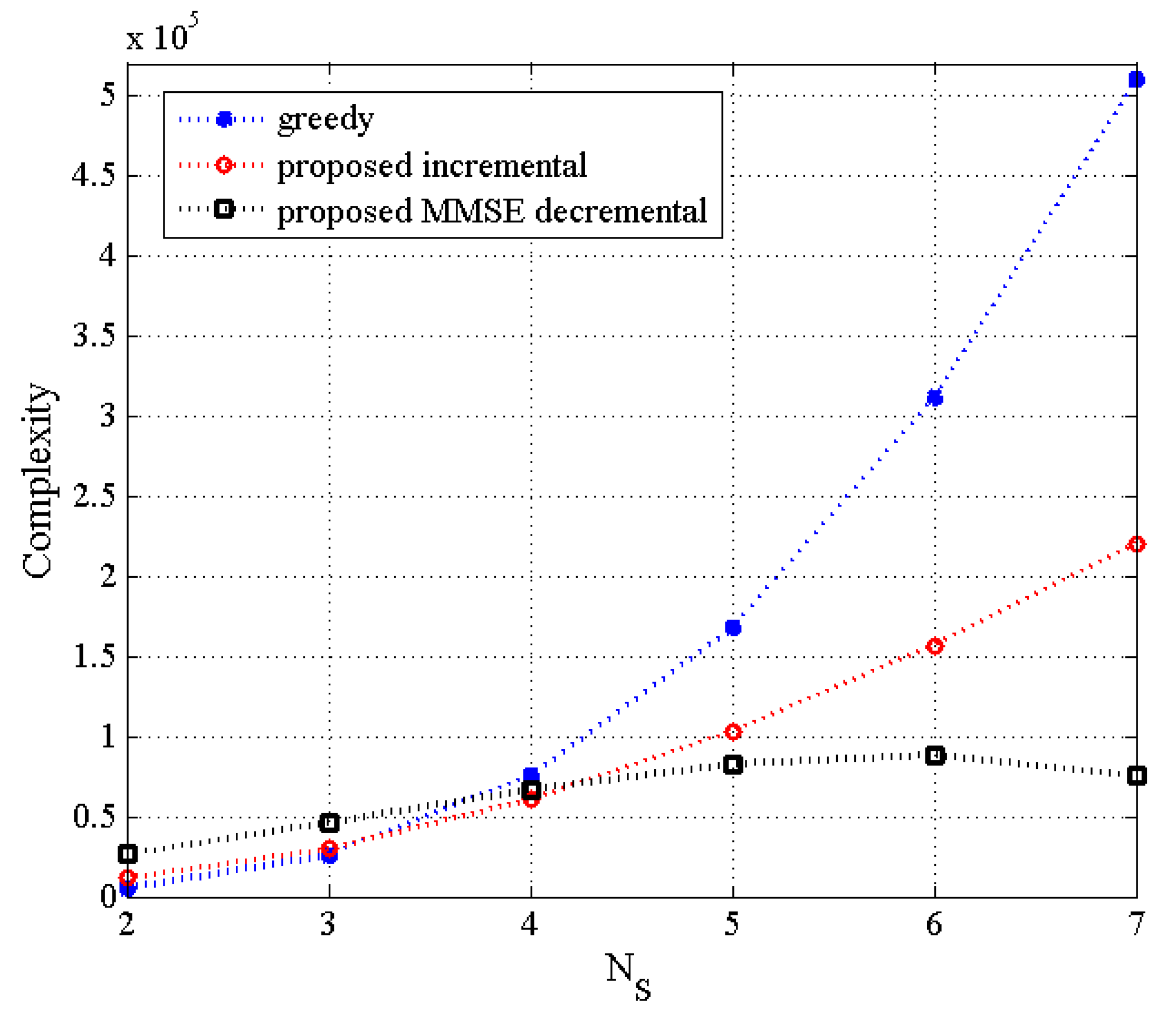
Figure 1, the complexity of the proposed incremental and decremental TAS selection algorithms is compared with that of the greedy algorithm as a function of the number of selected transmit antennas for
, where the number of users is assumed to be the same as that of the selected transmit antennas. It is deduced that for the small number of
in the
MU–STLC system with
, the complexity of the conventional greedy-based algorithm is comparable to the proposed algorithms. As
gets higher, the complexity of the greedy algorithm significantly increases and the proposed incremental algorithm obtains a much smaller complexity than the greedy one. On the other hand, the decremental algorithm achieves the smallest complexity for large
.
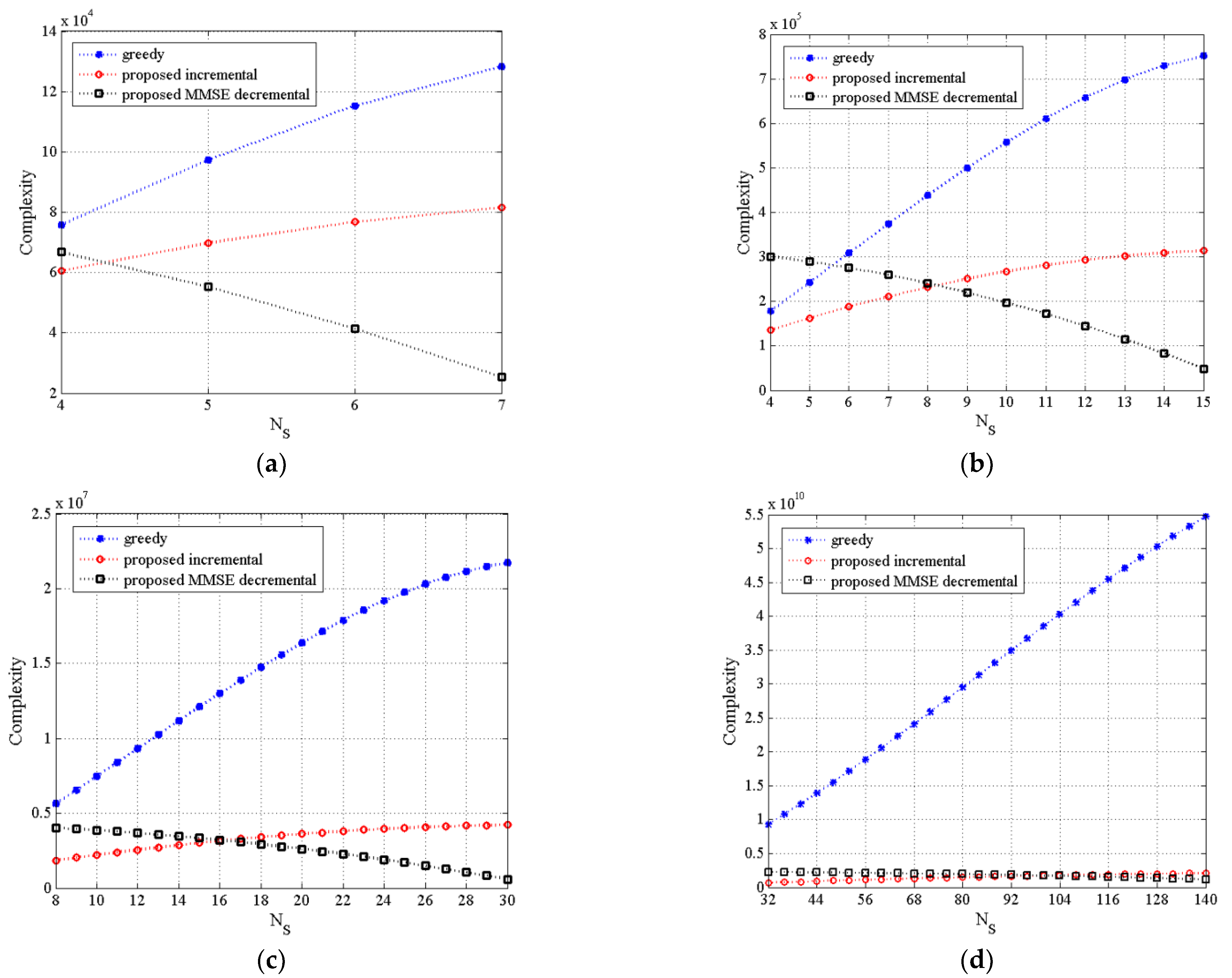
Figure 2a–d illustrate the complexity of three TAS selection algorithms as a function of varying
for
,
,
and
, and MU–STLC systems, respectively, where the number of users is invariant. For the small number of
of the
MU–STLC system in
Figure 2b, the conventional greedy-based algorithm has lower complexity than the proposed MMSE decremental algorithm but higher complexity than the proposed incremental algorithm. Meanwhile, it can be observed that the proposed incremental algorithm significantly reduces the complexity of the greedy algorithm for larger
. In addition, the rate of increase for the proposed incremental algorithm is much smaller than that of the greedy algorithm. On the other hand, the complexity of the decremental algorithm becomes lower as
increases. It is mainly due to reduction of
. Furthermore, it is found that the decremental algorithm can attain lower complexity than the proposed incremental algorithm when is greater than half of
. It should be noted that the proposed algorithms conduct
matrix inverse operations in each incremental/decremental step, which is the main reason to offer a low complexity for large antenna dimensions, compared to the conventional greedy-based algorithm requiring
matrix inverse operations.
5. Simulation Results
In this section, several TAS selection algorithms for the MU–STLC system with transmit antennas and users are evaluated through Monte Carlo simulations over static Raleigh flat-fading channels. Each user has two receive antennas. The SNR is defined as . In the case of , there is no TAS selection. We assume that the CSI is perfectly known at the transmitter of the MU–STLC system. The quadrature phase shift keying (QPSK) modulation is assumed. In the simulations, the BER performance of the linear precoded MU–STLC system is compared using the following TAS selection algorithms:
- (a)
SINR-greedy-based TAS selection [
14] (greedy);
- (b)
Proposed SNR-based efficient incremental TAS selection (proposed incremental);
- (c)
Proposed ZF-based efficient decremental TAS selection (proposed ZF decremental);
- (d)
Proposed MMSE-based efficient decremental TAS selection (proposed MMSE decremental);
- (e)
Optimal ZF-based TAS selection (optimal ZF);
- (f)
Optimal MMSE-based TAS selection (optimal MMSE).
It should be pointed out that the linear precoded MU–STLC TAS systems with (a), (b), (d), and (f) employ MMSE precoders at the transmitter, whereas the systems based on TAS selection of (c) and (e) use ZF precoders.
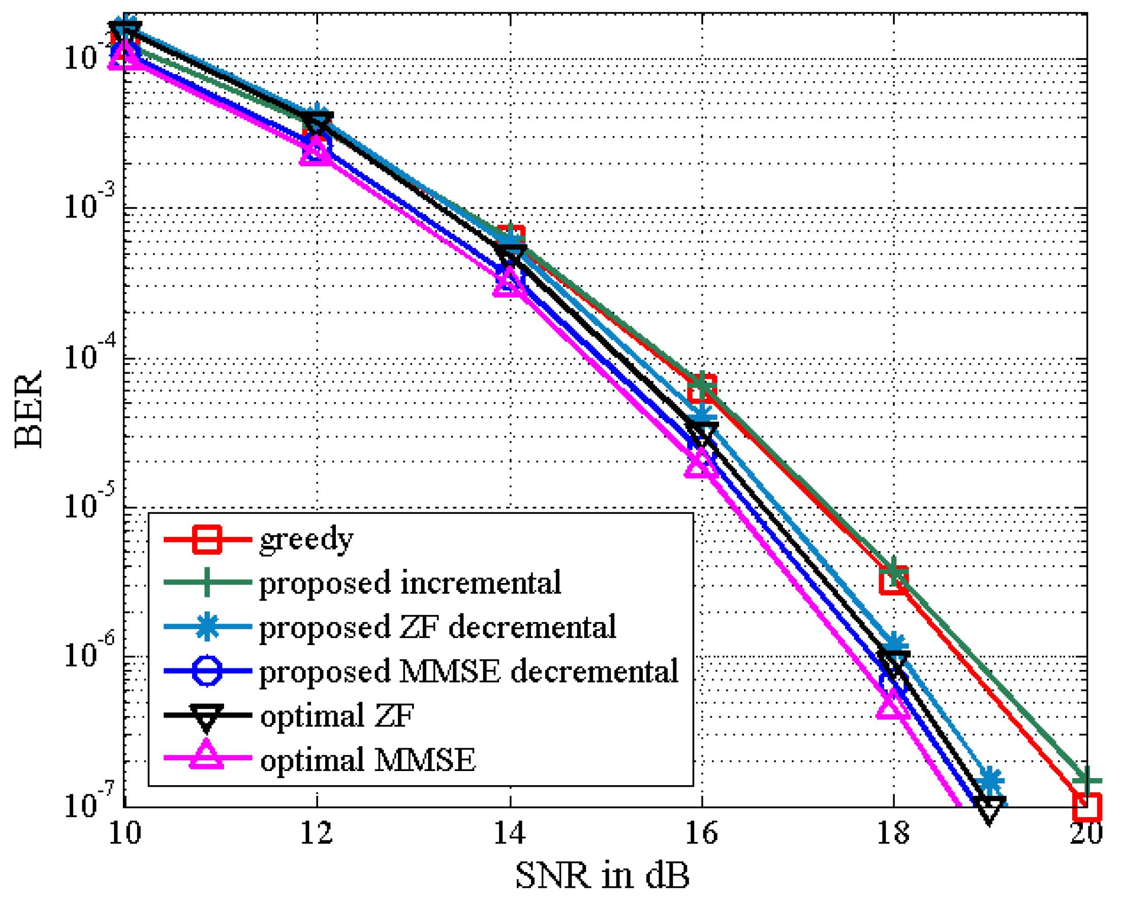
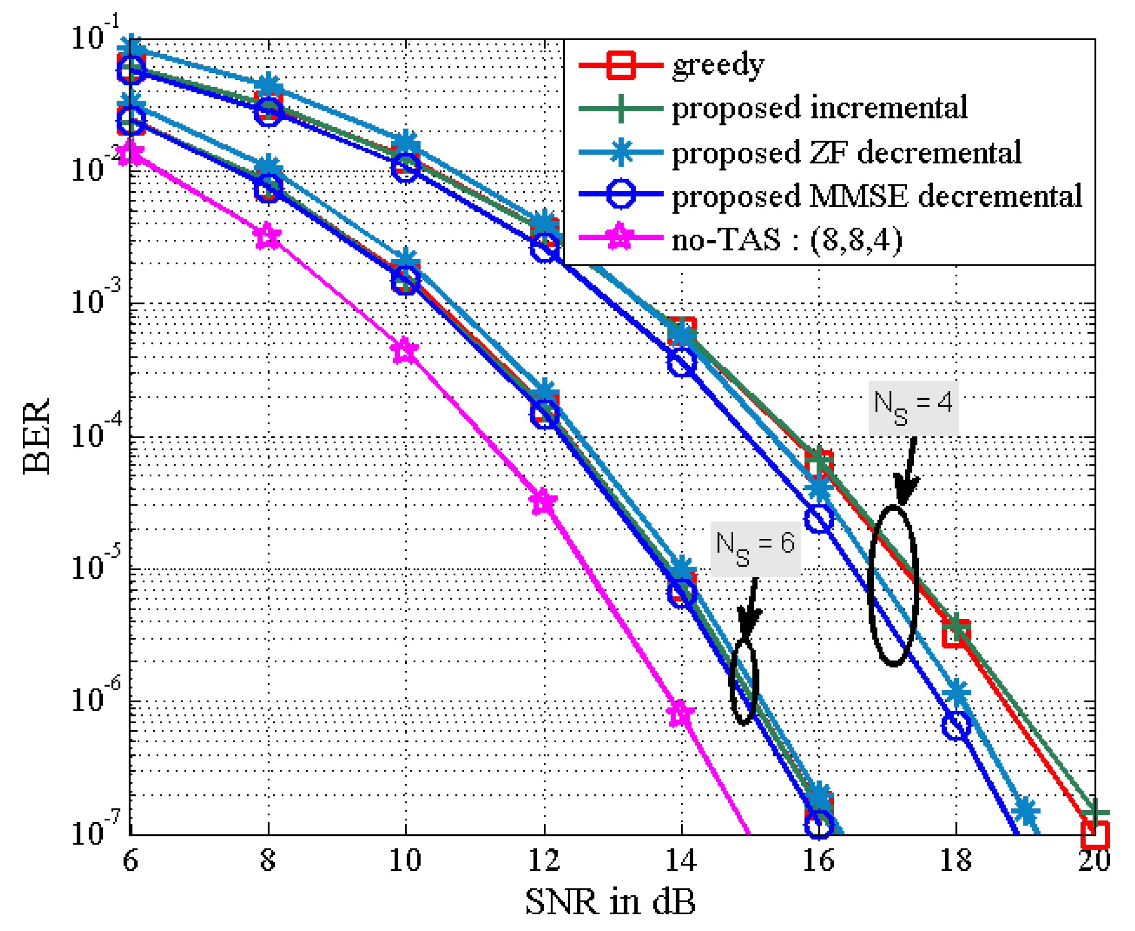
The BER performance of the proposed TAS selection algorithms is given in
Figure 3 in the scenario of
. We observe that the proposed incremental TAS selection algorithm achieves a slightly worse performance than the greedy algorithm in the high SNR regime with lower complexity (which is confirmed from
Figure 1). It is also shown that the proposed decremental TAS selection algorithm outperforms the greedy and proposed incremental algorithms. The performance of the latter may be poorly affected by an initially selected antenna. Furthermore, the proposed MMSE decremental TAS selection algorithm can achieve better BER performance compared to that of the proposed ZF decremental TAS selection one. In addition, the BER results of the proposed ZF and MMSE decremental selection algorithms are close to those of the optimal exhaustive search-based ZF and MMSE TAS selection algorithms, respectively.
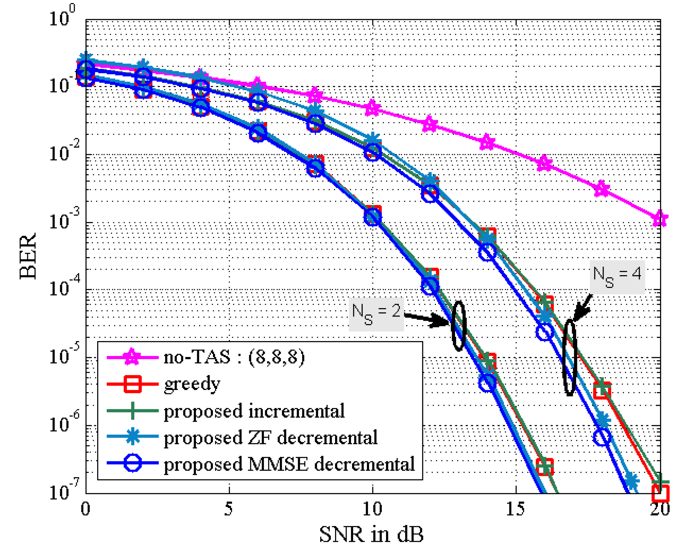
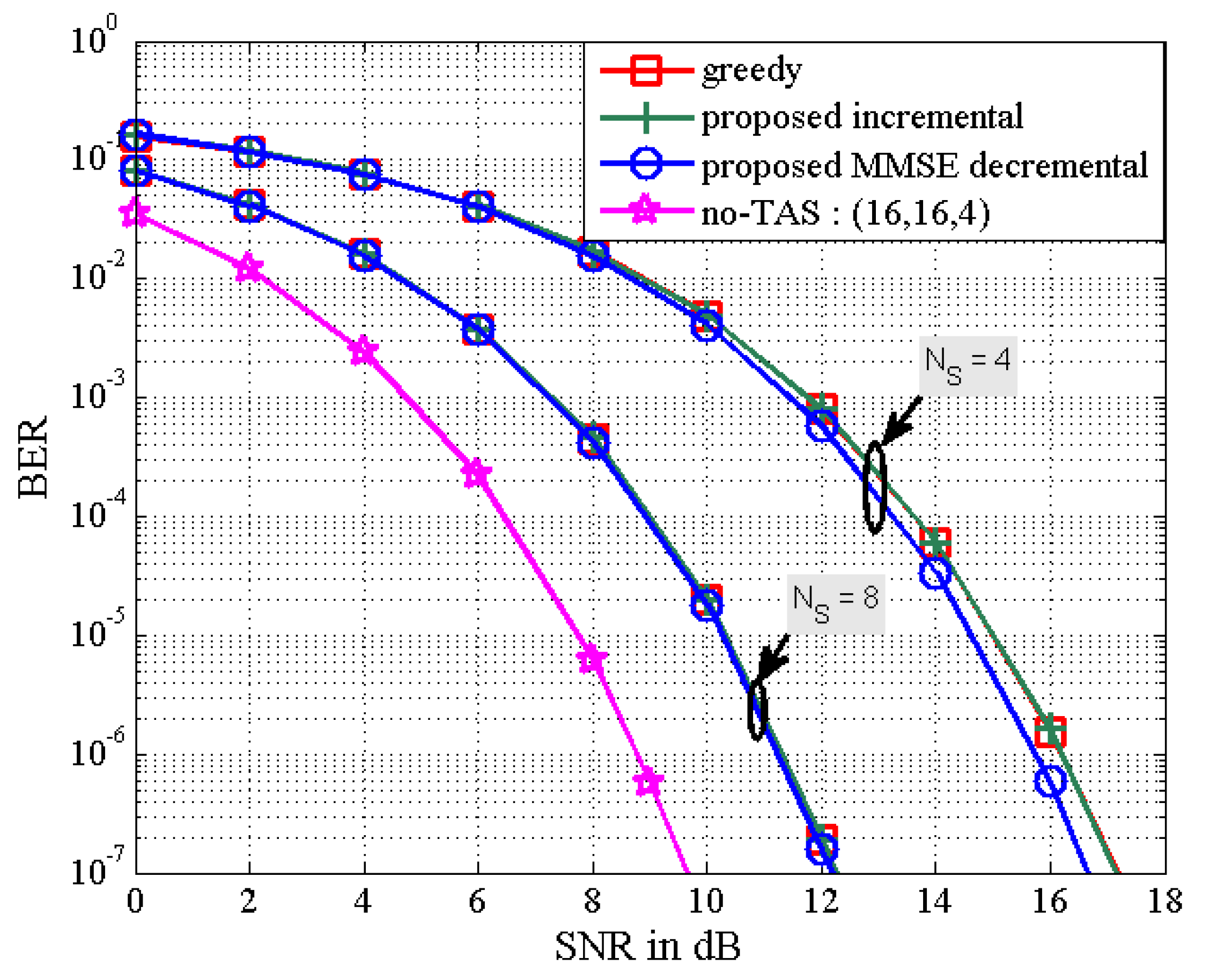
Figure 4 depicts the BER results of the proposed TAS selection algorithms for the
MU–STLC system when
is equal to
. It is assumed that the values of
are given as
. Note that
indicates no TAS selection case. It is observed that the BER performance of all the TAS selection algorithms improves as
decreases. The good performance for small
results from the decreased multiuser interference. Especially, the proposed MMSE decremental TAS selection algorithm is shown to provide the best BER performance. In this scenario, the computational complexity of the greedy, the proposed incremental, and the proposed MMSE decremental algorithms is shown in
Figure 1. For
, the complexity of the greedy algorithm is the smallest, while the BER performance of the greedy algorithm is slightly less than that of the proposed MMSE decremental algorithm and similar to that of the proposed incremental algorithm. We can observe that the BER performance difference between the proposed ZF and MMSE decremental algorithms becomes smaller as the diversity gain gets larger. It should be noted that the diversity gain of the
MU–STLC system is larger than that of the
case.
In
Figure 5 and
Figure 6, as the number of active transmit antennas decreases in the proposed MMSE decremental TAS selection algorithm, the received SNR penalty increases. Here, the number of users is fixed as
. It is also seen in
Figure 5 that the performance gap between the proposed decremental selection algorithms and the greedy algorithm is bigger as the number of selected antennas is smaller. It is observed in
Figure 6 that when the diversity gain is high, all the greedy, the proposed incremental, and the proposed MMSE decremental algorithms offer similar BER performance. In
Figure 5, the SNR penalties are approximately given as 1 dB and 3.8 dB, respectively, for
and
. In
Figure 6, they are approximated by 2.5 dB and 6.75 dB, respectively, for
and
. They are well agreed with analytical results in
Figure 7, which is obtained from (50). Thus, we can evaluate the received SNR penalty owing to TAS selection by using (50) for massive MU–STLC MIMO systems.
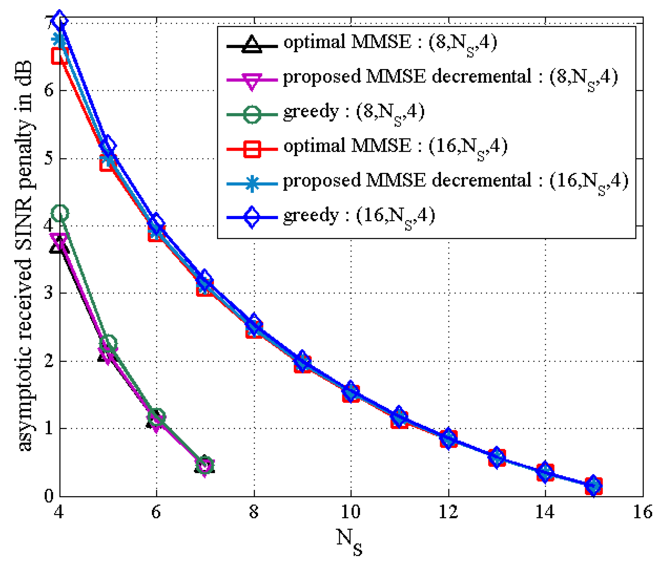
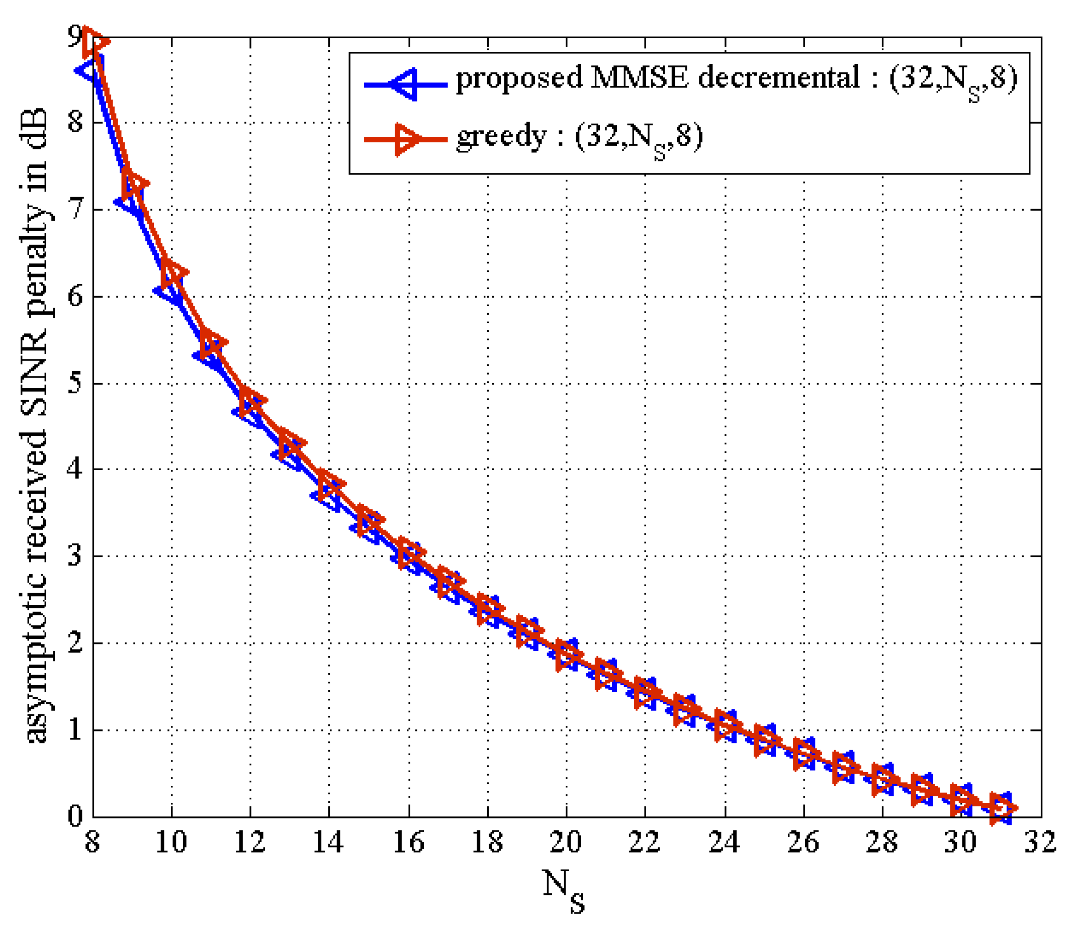
Figure 8 exhibits the asymptotic received SINR penalty as a function of
for the MU–STLC system with
and
. It is found that as the number of selected transmit antennas increases, the SINR penalty decreases. Furthermore, we can expect from the received SINR penalty analysis that without BER simulations, the BER results of the proposed MMSE decremental and conventional greedy algorithms are similar for the
MU–STLC system.
Finally,
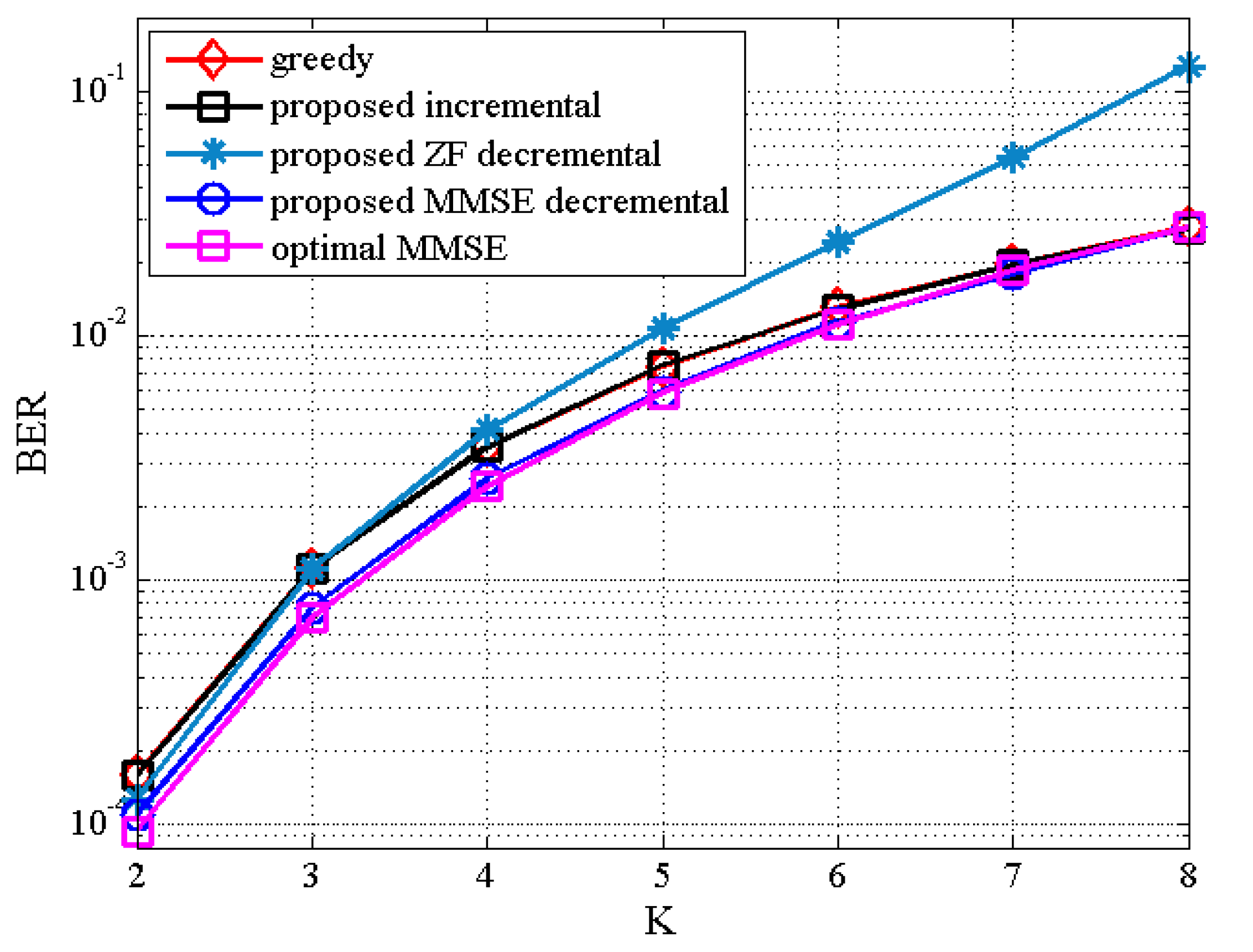
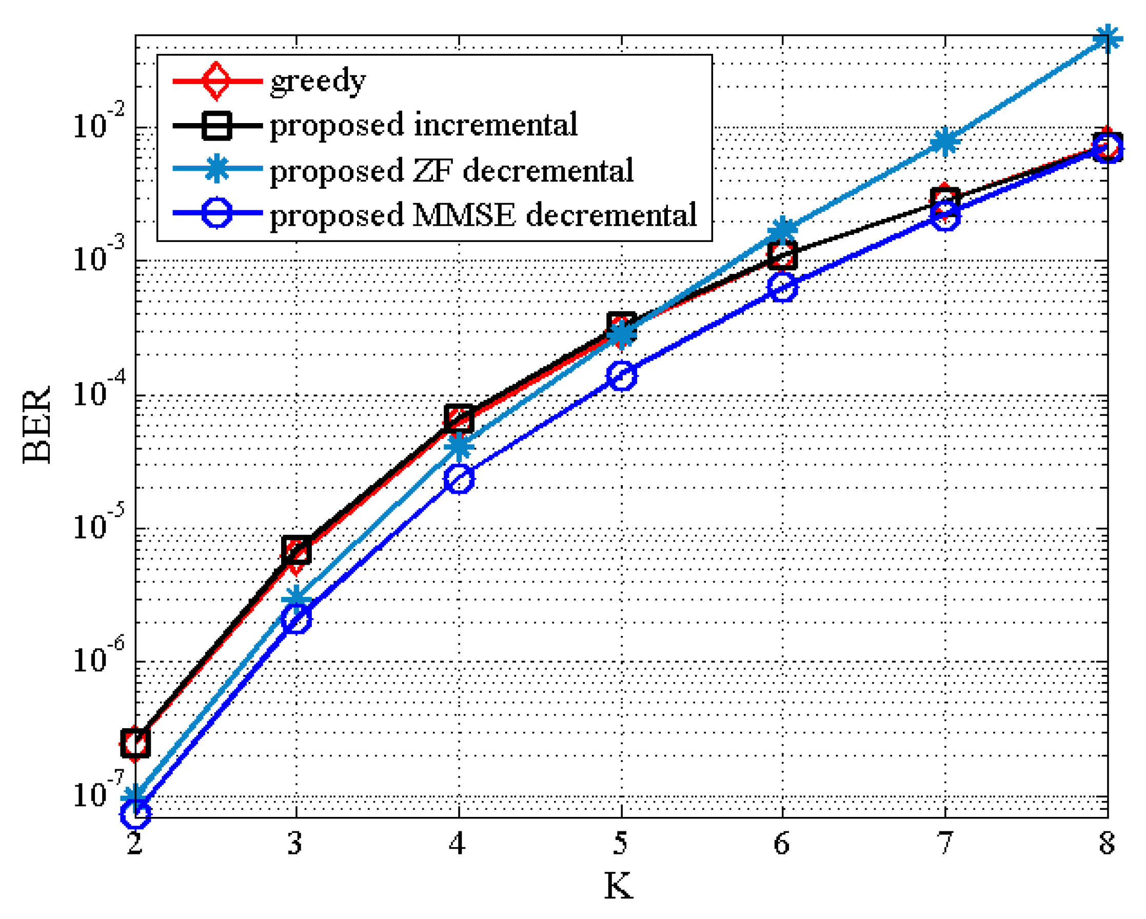
Figure 9 and
Figure 10 illustrate the BER results of the proposed TAS selection algorithms as a function of
for the
MU–STLC system with
when
dB and
dB, respectively, are given. The BER performance worsens for all TAS selection algorithms as
increases. It is due to the increased multiuser interference. Particularly, the proposed ZF decremental TAS selection algorithm for large
achieves poor performance owing to large multiuser interference. On the other hand, it is seen that the proposed MMSE decremental TAS selection algorithm achieves the BER performance close to the optimal algorithm and outperforms the other TAS selection schemes for
. This implies that the proposed MMSE decremental selection algorithm is able to effectively suppress the multiuser interference. For this scenario, the comparison of computational complexity has been given in
Figure 1. Recall that the proposed MMSE decremental TAS selection algorithm has the lowest complexity for
.


