
A Review on Low-Cost Microwave Doppler Radar Systems for Structural Health Monitoring


Abstract
1. Introduction
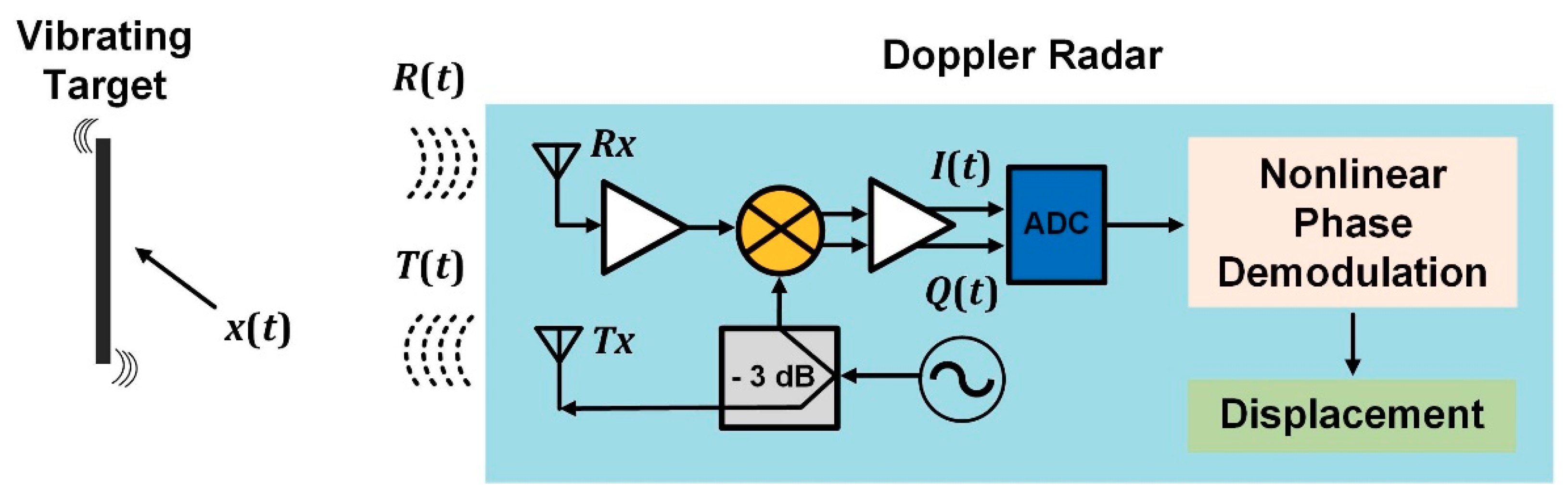
2. Theory of Low-Cost Doppler Radars for Structural Health Monitoring
3. Recent Advancements for SHM Based on Vibration Analysis
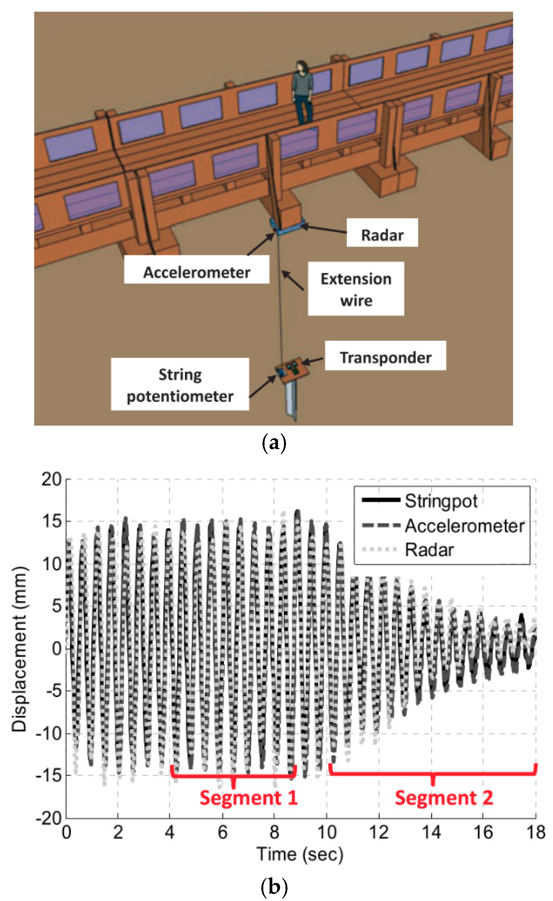
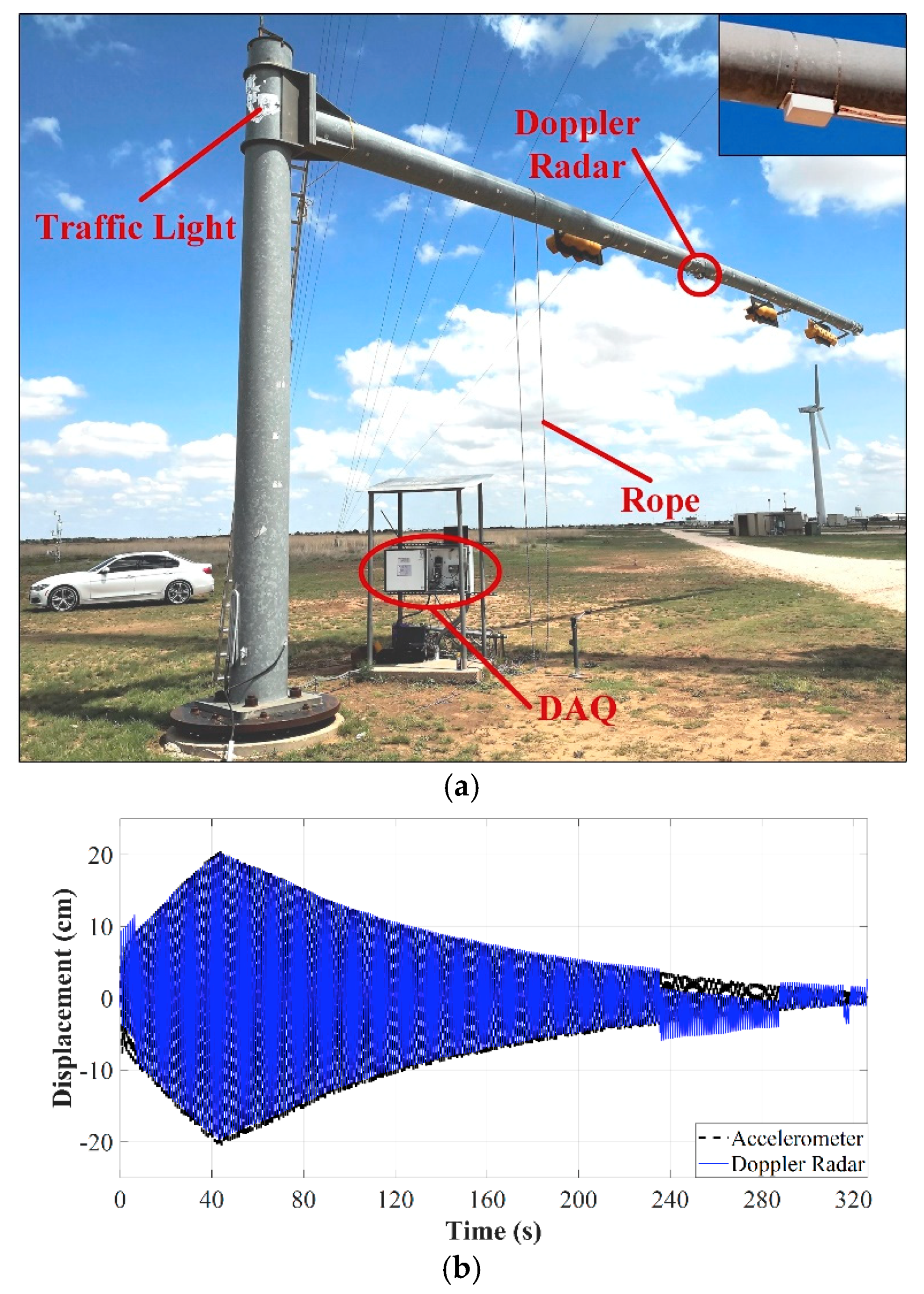
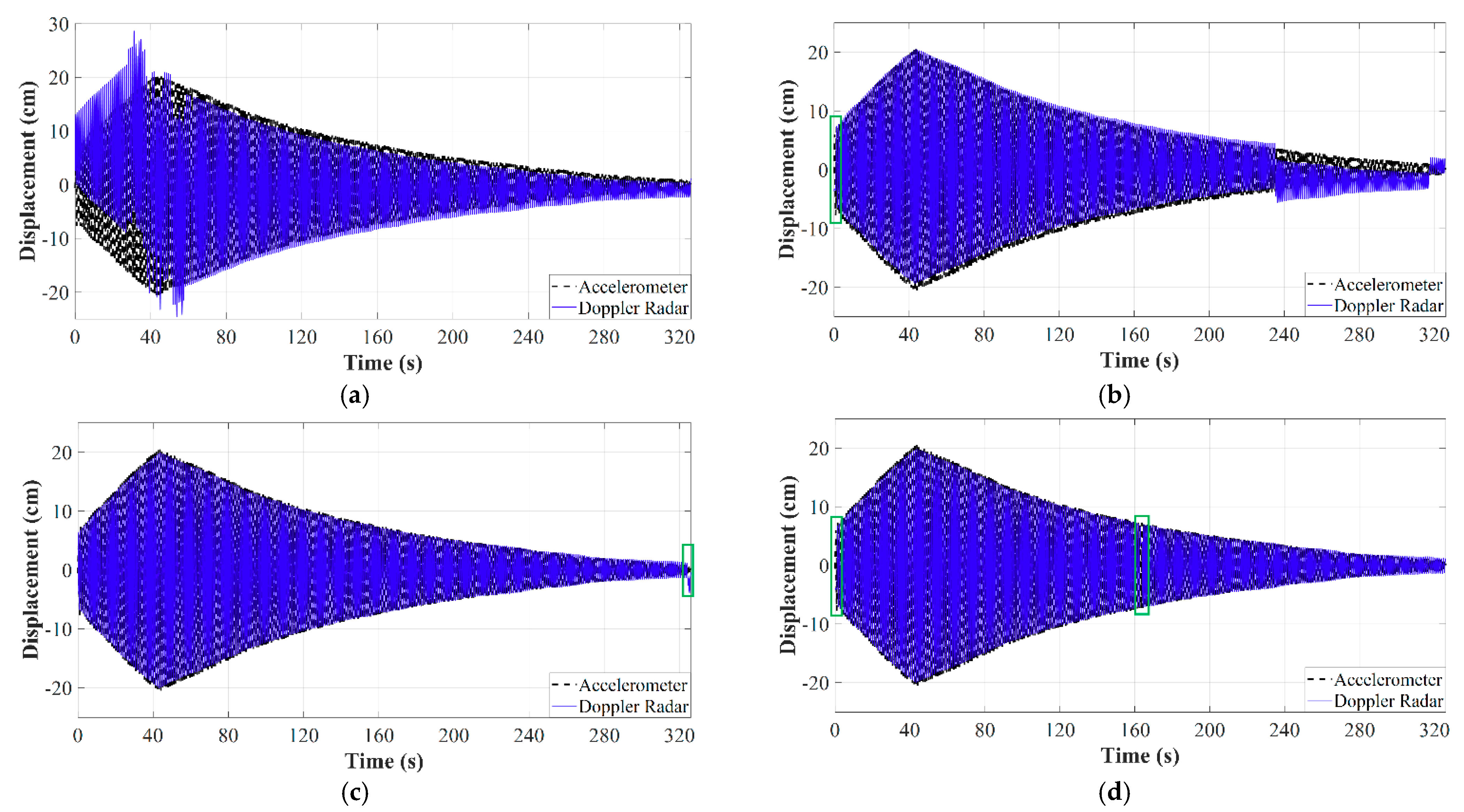
3.1. Doppler Radar on Active Backscattering Mode
3.2. Doppler Radar Network on Active Backscattering Mode
3.3. Doppler Radar on Passive Backscattering Mode
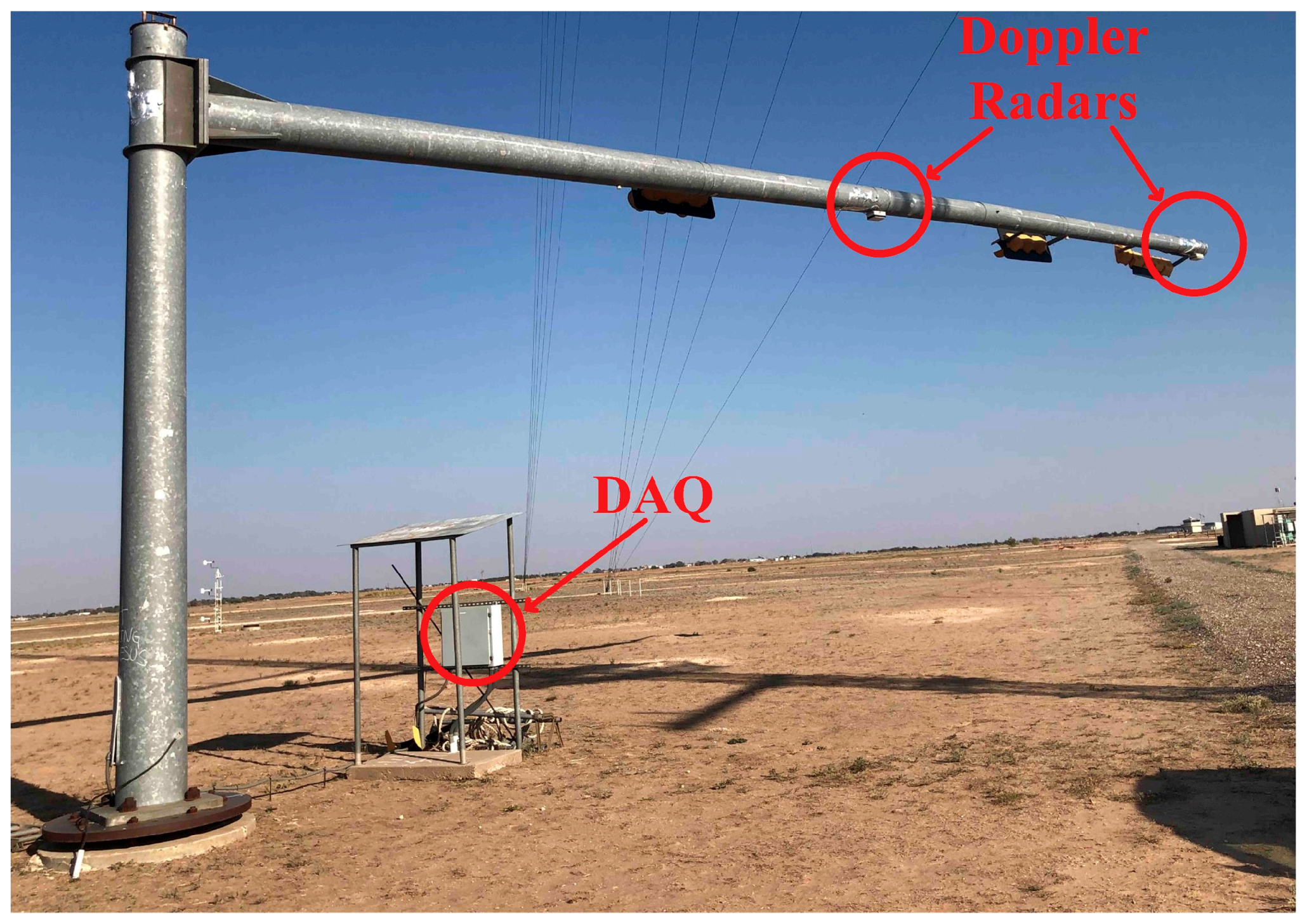
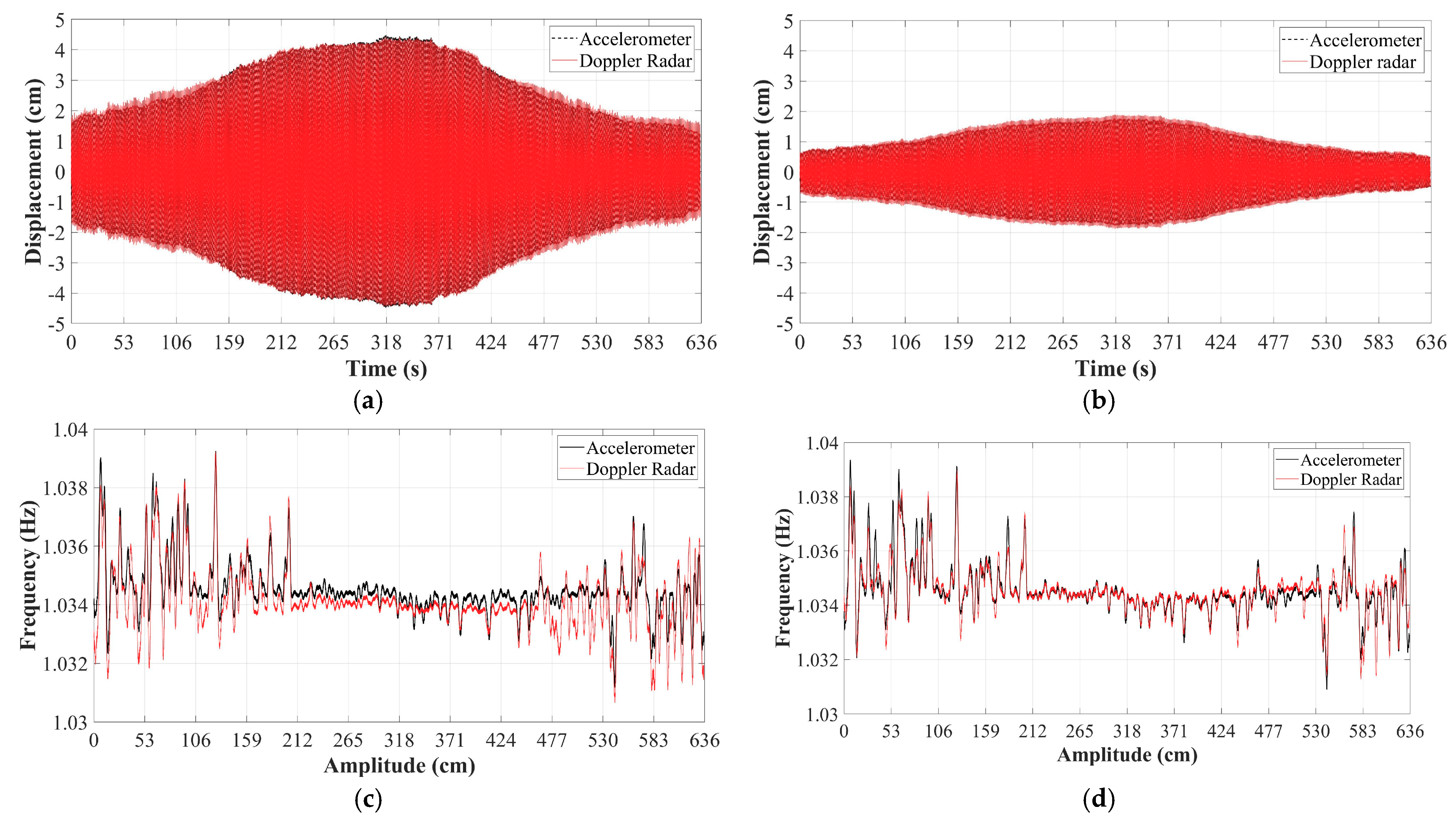
3.4. Doppler Radar Array on Passive Backscattering Mode
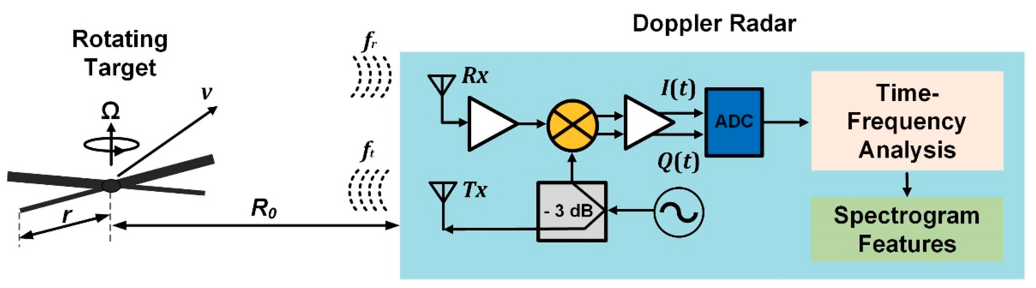
4. Recent Advancements for SHM Based on the Analysis of Time-Doppler Signatures
5. Conclusions
Author Contributions
Funding
Conflicts of Interest
References
- James, R.J. A history of radar. IEE Rev. 1989, 35, 343–349. [Google Scholar] [CrossRef]
- Peng, Z.; Muñoz-Ferreras, J.M.; Tang, Y.; Liu, C.; Gómez-García, R.; Ran, L.; Li, C. A Portable FMCW Interferometry Radar with Programmable Low-IF Architecture for Localization, ISAR Imaging, and Vital Sign Tracking. IEEE Trans. Microw. Theory Tech. 2017, 65, 1334–1344. [Google Scholar] [CrossRef]
- Peng, Z.; Ran, L.; Li, C. A K -Band Portable FMCW Radar with Beamforming Array for Short-Range Localization and Vital-Doppler Targets Discrimination. IEEE Trans. Microw. Theory Tech. 2017, 65, 3443–3452. [Google Scholar] [CrossRef]
- Peng, Z.; Li, C. A Portable K -Band 3-D MIMO Radar with Nonuniformly Spaced Array for Short-Range Localization. IEEE Trans. Microw. Theory Tech. 2018, 68, 5075–5086. [Google Scholar] [CrossRef]
- Nasr, I.; Jungmaier, R.; Baheti, A.; Noppeney, D.; Bal, J.S.; Wojnowski, M.; Karagozler, E.; Raja, H.; Lien, J.; Poupyrev, I.; et al. A Highly Integrated 60 GHz 6-Channel Transceiver with Antenna in Package for Smart Sensing and Short-Range Communications. IEEE J. Solid-State Circuits 2016, 51, 2066–2076. [Google Scholar] [CrossRef]
- Li, C.; Xiao, Y.; Lin, J. Experiment and Spectral Analysis of a Low-Power Ka-Band Heartbeat Detector Measuring from Four Sides of a Human Body. IEEE Trans. Microw. Theory Tech. 2006, 54, 4464–4471. [Google Scholar] [CrossRef]
- Li, C.; Lin, J. Random Body Movement Cancellation in Doppler Radar Vital Sign Detection. IEEE Trans. Microw. Theory Tech. 2008, 56, 3143–3152. [Google Scholar]
- Xiong, J.; Hong, H.; Zhang, H.; Wang, N.; Chu, H.; Zhu, X. Multitarget Respiration Detection with Adaptive Digital Beamforming Technique Based on SIMO Radar. IEEE Trans. Microw. Theory Tech. 2020, 68, 4814–4824. [Google Scholar] [CrossRef]
- Wang, P.; Ma, Y.; Liang, F.; Zhang, Y.; Yu, X.; Li, Z.; An, Q.; Lv, H.; Wang, J. Non-Contact Vital Signs Monitoring of Dog and Cat Using a UWB Radar. Animals 2020, 10, 205. [Google Scholar] [CrossRef]
- Rodriguez, D.; Li, C. Sensitivity and Distortion Analysis of a 125-GHz Interferometry Radar for Submicrometer Motion Sensing Applications. IEEE Trans. Microw. Theory Tech. 2019, 67, 5384–5395. [Google Scholar] [CrossRef]
- Wang, Y.; Ling, H.; Chen, V.C. ISAR motion compensation via adaptive joint time-frequency technique. IEEE Trans. Aerosp. Electron. Syst. 1998, 34, 670–677. [Google Scholar] [CrossRef]
- Ding, C.; Hong, H.; Zou, Y.; Chu, H.; Zhu, X.; Fioranelli, F.; Le Kernec, J.; Li, C. Continuous Human Motion Recognition with a Dynamic Range-Doppler Trajectory Method Based on FMCW Radar. IEEE Trans. Geosci. Remote Sens. 2019, 57, 6821–6831. [Google Scholar] [CrossRef]
- Ram, S.S.; Ling, H. Through-wall tracking of human movers using joint Doppler and array processing. IEEE Trans. Geosci. Remote Sens. 2008, 5, 537–541. [Google Scholar] [CrossRef]
- Kim, Y.; Ling, H. Human activity classification based on micro-Doppler signatures using an artificial neural network. In Proceedings of the IEEE Antennas and Propagation Society International Symposium, San Diego, CA, USA, 5–11 July 2008; pp. 1–4. [Google Scholar]
- Kim, Y.; Ling, H. Human activity classification based on micro-Doppler signatures using a support vector machine. IEEE Trans. Geosci. Remote Sens. 2009, 47, 1328–1337. [Google Scholar]
- Ram, S.S.; Christianson, C.; Kim, Y.; Ling, H. Simulation and analysis of human micro-Dopplers in through-wall environments. IEEE Trans. Geosci. Remote Sens. 2010, 48, 2015–2023. [Google Scholar] [CrossRef]
- Rodrigues, D.V.Q.; Li, C. Hand gesture recognition using FMCW radar in multi-person scenario. In Proceedings of the IEEE MTT-S Radio and Wireless Symposium (RWS), Virtual Conference. 17–20 January 2021. [Google Scholar]
- Rodrigues, D.V.Q.; Li, C. Noncontact exercise monitoring in multi-person scenario with frequency-modulated continuous-wave radar. In Proceedings of the IEEE MTT-S International Microwave Biomedical Conference (IMBioC), Virtual Conference. 14–17 December 2020. [Google Scholar]
- Li, Y.; Peng, Z.; Pal, R.; Li, C. Potential Active Shooter Detection Based on Radar Micro-Doppler and Range-Doppler Analysis Using Artificial Neural Network. IEEE Sens. J. 2019, 19, 1052–1063. [Google Scholar] [CrossRef]
- Gu, C.; Salmani, Z.; Zhang, H.; Li, C. Antenna array technology for radar respiration measurement in motion-adaptive lung cancer radiotherapy. In Proceedings of the IEEE Topical Conference on Biomedical Wireless Technologies, Networks, and Sensing Systems (BioWireleSS), Santa Clara, CA, USA, 15–18 January 2012; pp. 21–24. [Google Scholar]
- Gu, C.; Li, R.; Zhang, H.; Fung, A.Y.C.; Torres, C.; Jiang, S.B.; Li, C. Accurate respiration measurement using DC-coupled continuous-wave radar sensor for motion-adaptive cancer radiotherapy. IEEE Trans. Biomed. Eng. 2012, 59, 3117–3123. [Google Scholar] [PubMed]
- Klemm, M.; Craddock, I.J.; Leendertz, J.A.; Preece, A.; Benjamin, R. Radar-Based Breast Cancer Detection Using a Hemispherical Antenna Array—Experimental Results. IEEE Trans. Antennas Propag. 2009, 57, 1692–1704. [Google Scholar] [CrossRef]
- Chen, V.C.; Ling, H. Time-Frequency Transforms for Radar Imaging and Signal Analysis; Artech House: Norwood, MA, USA, 2002. [Google Scholar]
- Li, J.; Ling, H. Application of adaptive chirplet representation for ISAR feature extraction from targets with rotating parts. IEE Proc. Radar Sonar Navig. 2003, 150, 284–291. [Google Scholar] [CrossRef]
- Naqvi, A.; Yang, S.-T.; Ling, H. Investigation of Doppler features from wind turbine scattering. IEEE Antennas Wireless Propag. Lett. 2010, 9, 485–488. [Google Scholar] [CrossRef]
- Li, C.J.; Ling, H. On simulating the high-resolution radar image of a wind turbine. In Proceedings of the 10th European Conference on Antennas and Propagation (EuCAP), Davos, Switzerland, 10–15 April 2016; pp. 1–3. [Google Scholar]
- Whitelonis, N.; Yang, S.-T.; Ling, H. Application of nearfield to far-field transformation to Doppler features from wind turbine scattering. IEEE Trans. Antennas Propag. 2012, 60, 1660–1665. [Google Scholar] [CrossRef]
- Muñoz-Ferreras, J.-M.; Peng, Z.; Tang, Y.; Gómez-García, R.; Liang, D.; Li, C. Short-range Doppler-radar signatures from industrial wind turbines: Theory, simulations, and measurements. IEEE Trans. Instrum. Meas. 2016, 65, 2108–2119. [Google Scholar] [CrossRef]
- Thenozhi, S.; Yu, W.; Garrido, R. A novel numerical integrator for structural health monitoring. In Proceedings of the 5th International Symposium on Resilient Control Systems, Salt Lake City, UT, USA, 14–16 August 2012; pp. 92–97. [Google Scholar]
- Srivastava, S.K.; Lukowski, T.I.; Gray, R.B.; Shepherd, N.W.; Hawkins, R.K. RADARSAT: Image quality management and performance results. In Proceedings of the Canadian Conference on Electrical and Computer Engineering, Calgary, AB, Canada, 26–29 May 1996; Volume 1, pp. 21–23. [Google Scholar]
- Farrar, C.R.; Darling, T.W.; MigliorI, A.; Baker, W.E.; Adams, M. Microwave interferometers for non-contact vibration measurements on large structures. Mech. Syst. Signal Process. 1999, 13, 241–253. [Google Scholar] [CrossRef]
- Pieraccini, M.; Tarchi, D.; Rudolf, H.; Leva, D.; Luzi, G.; Bartoli, G.; Atzeni, C. Structural static testing by interferometric synthetic radar. NDT E Int. 2000, 33, 565–570. [Google Scholar] [CrossRef]
- Tarchi, D.; Casagli, N.; Fanti, R.; Leva, D.D.; Luzi, G.; Pasuto, A.; Pieraccini, M.; Silvano, S. Landslide monitoring by using ground-based SAR interferometry: An example of application to the Tessina landslide in Italy. Eng. Geol. 2003, 68, 15–30. [Google Scholar] [CrossRef]
- Atzeni, C.; Bicci, A.; Dei, D.; Fratini, M.; Pieraccini, M. Remote survey of the Leaning Tower of Pisa by Interferometric Sensing. IEEE Geosci. Remote Sens. Lett. 2010, 7, 185–189. [Google Scholar] [CrossRef]
- Pieraccini, M.; Papi, F.; Donati, N. I-Q imbalance correction of microwave displacement sensors. Electron. Lett. 2015, 51, 1021–1023. [Google Scholar] [CrossRef]
- Luzi, G.; Crosetto, M.; Fernández, E. Radar interferometry for monitoring the vibration characteristics of buildings and civil structures: Recent case studies in Spain. Sensors 2017, 17, 669. [Google Scholar] [CrossRef]
- Di Pasquale, A.; Nico, G.; Pitullo, A.; Prezioso, G. Monitoring Strategies of Earth Dams by Ground-Based Radar Interferometry: How to Extract Useful Information for Seismic Risk Assessment. Sensors 2018, 18, 244. [Google Scholar] [CrossRef]
- Hu, J.; Guo, J.; Xu, Y.; Zhou, L.; Zhang, S.; Fan, K. Differential Ground-Based Radar Interferometry for Slope and Civil Structures Monitoring: Two Case Studies of Landslide and Bridge. Remote Sens. 2019, 11, 2887. [Google Scholar] [CrossRef]
- Moll, J.; Bechtel, K.; Hils, B.; Krozer, V. Mechanical Vibration Sensing for Structural Health Monitoring Using a Millimeter-Wave Doppler Radar Sensor. In Proceedings of the 7th European Workshop on Structural Health Monitoring (EWSHM), Nantes, France, 8–11 July 2014; pp. 1802–1808. [Google Scholar]
- Diaferio, M.; Fraddosio, A.; Daniele Piccioni, M.; Castellano, A.; Mangialardi, L.; Soria, L. Some issues in the structural health monitoring of a railway viaduct by ground-based radar interferometry. In Proceedings of the IEEE Workshop on Environmental, Energy, and Structural Monitoring Systems (EESMS), Milan, Italy, 24–25 July 2017; pp. 1–6. [Google Scholar]
- Pieraccini, M.; Betti, M.; Forcellini, D.; Dei, D.; Papi, F.; Bartoli, G.; Facchini, L.; Corazzi, R.; Cerisano Kovacevic, V. Radar detection of pedestrian-induced vibrations on Michelangelo’s David. PLoS ONE 2017, 12, e0174480. [Google Scholar] [CrossRef]
- Luzi, G.; Crosetto, M.; Angelats, E.; Fernández, E. An interferometric radar sensor for monitoring the vibrations of structures at short. In MATEC Web of Conferences; EDP Sciences: Les Ulis, France, 2018; Volume 148, p. 01005. [Google Scholar]
- Viviani, F.; Michelini, A.; Mayer, L.; Conni, F. IBIS-ArcSAR: An Innovative Ground-Based SAR System for Slope Monitoring. In Proceedings of the IGARSS—IEEE International Geoscience and Remote Sensing Symposium, Valencia, Spain, 22–27 July 2018; pp. 1348–1351. [Google Scholar]
- Liu, X.; Li, S.; Tong, X. Two-Level W-ESMD Denoising for Dynamic Deflection Measurement of Railway Bridges by Microwave Interferometry. IEEE J. Sel. Top. Signal Process. 2018, 11, 4874–4883. [Google Scholar] [CrossRef]
- Miccinesi, L.; Pieraccini, M. Monostatic/Bistatic Interferometric Radar for Monitoring Slander Structures. In Proceedings of the IEEE Conference on Antenna Measurements & Applications (CAMA), Kuta, Bali, Indonesia, 23–25 October 2019; pp. 1–4. [Google Scholar]
- Castagnetti, C.; Bassoli, E.; Vincenzi, L.; Mancini, F. Dynamic Assessment of Masonry Towers Based on Terrestrial Radar Interferometer and Accelerometers. Sensors 2019, 19, 1319. [Google Scholar] [CrossRef] [PubMed]
- Pieraccini, M.; Miccinesi, L. Ground-Based Radar Interferometry: A Bibliographic Review. Remote Sens. 2019, 11, 1029. [Google Scholar] [CrossRef]
- Pieraccini, M.; Miccinesi, L. An Interferometric MIMO Radar for Bridge Monitoring. IEEE Geosci. Remote Sens. Lett. 2019, 16, 1383–1387. [Google Scholar] [CrossRef]
- Pieraccini, M.; Miccinesi, L.; Abdorazzagh Nejad, A.; Naderi Nejad Fard, A. Experimental Dynamic Impact Factor Assessment of Railway Bridges through a Radar Interferometer. Remote Sens. 2019, 11, 2207. [Google Scholar] [CrossRef]
- Wang, Y.; Dai, K.; Xu, Y.; Zhu, W.; Lu, W.; Shi, Y.; Mei, Z.; Xue, S.; Faulkner, K. Field Testing of Wind Turbine Towers with Contact and Noncontact Vibration Measurement Methods. J. Perform. Constr. Facil. 2020, 34, 04019094. [Google Scholar] [CrossRef]
- Nico, G.; Prezioso, G.; Masci, O.; Artese, S. Dynamic Modal Identification of Telecommunication Towers Using Ground Based Radar Interferometry. Remote Sens. 2020, 12, 1211. [Google Scholar] [CrossRef]
- Huang, Q.; Wang, Y.; Luzi, G.; Crosetto, M.; Monserrat, O.; Jiang, J.; Zhao, H.; Ding, Y. Ground-Based Radar Interferometry for Monitoring the Dynamic Performance of a Multitrack Steel Truss High-Speed Railway Bridge. Remote Sens. 2020, 12, 2594. [Google Scholar] [CrossRef]
- Artese, S.; Nico, G. TLS and GB-RAR Measurements of Vibration Frequencies and Oscillation Amplitudes of Tall Structures: An Application to Wind Towers. Appl. Sci. 2020, 10, 2237. [Google Scholar] [CrossRef]
- Miccinesi, L.; Michelini, A.; Pieraccini, M. Blurring/Clutter Mitigation in Quarry Monitoring by Ground-Based Synthetic Aperture Radar. IEEE Trans. Geosci. Remote Sens. 2021. [Google Scholar] [CrossRef]
- Miccinesi, L.; Beni, A.; Pieraccini, M. Multi-Monostatic Interferometric Radar for Bridge Monitoring. Electronics 2021, 10, 247. [Google Scholar] [CrossRef]
- Park, B.; Boric-Lubecke, O.; Lubecke, V. Arctangent demodulation with DC offset compensation in quadrature Doppler radar receiver systems. IEEE Trans. Microw. Theory Tech. 2007, 55, 10731079. [Google Scholar] [CrossRef]
- Droitcour, A.D.; Boric-Lubecke, O.; Lubecke, V.M.; Lin, J.; Kovac, G.T. Range correlation and I/Q performance benefits in single-chip silicon Doppler radars for noncontact cardiopulmonary monitoring. IEEE Trans. Microw. Theory Tech. 2004, 52, 838–848. [Google Scholar] [CrossRef]
- Wei, C.; Lin, J. Digitally assisted low IF architecture for noncontact vital sign detection. In Proceedings of the IEEE MTT-S International Microwave Symposium, Phoenix, AZ, USA, 17–22 May 2015; pp. 1–4. [Google Scholar]
- Gu, C. Short-Range Noncontact Sensors for Healthcare and Other Emerging Applications: A Review. Sensors 2016, 16, 1169. [Google Scholar] [CrossRef]
- Ma, X.; Li, L.; You, X.; Lin, J. Envelope detection for a double-sideband Low IF CW radar. In Proceedings of the IEEE/MTT-S International Microwave Symposium—IMS, Philadelphia, PA, USA, 10–15 June 2018; pp. 240–243. [Google Scholar]
- Guan, S.; Rice, J.A.; Li, C.; Li, Y.; Wang, G. Dynamic and static structural displacement measurement using backscattering DC coupled radar. Smart Struct. Syst. 2015, 16, 521–535. [Google Scholar] [CrossRef]
- Gu, C.; Wang, G.; Rice, J.A.; Li, C. Interferometric Radar Sensor with Active Transponders for Signal Boosting and Clutter Rejection in Structural Health Monitoring. In Proceedings of the IEEE/MTT-S International Microwave Symposium Digest, Montreal, QC, Canada, 17–22 June 2012; pp. 1–3. [Google Scholar]
- Rice, J.A.; Gu, C.; Li, C.; Guan, S. A radar-based sensor network for bridge displacement measurements. In Proceedings of the SPIE Sensor Smart Structures Technologies for Civil Mechanical, and Aerospace Systems, San Diego, CA, USA, 3 April 2012; p. 83450I. [Google Scholar]
- Guan, S.; Rice, J.A.; Li, C.; Li, Y.; Wang, G. Structural displacement measurements using DC coupled radar with active transponder. Struct. Control Health Monitor. 2016, 24, 1909. [Google Scholar] [CrossRef]
- Wang, J.; Rodriguez, D.; Mishra, A.; Nallabolu, P.R.; Karp, T.; Li, C. 24-GHz Impedance-Modulated BPSK Tags for Range Tracking and Vital Signs Sensing of Multiple Targets Using an FSK Radar. IEEE Trans. Microw. Theory Tech. 2021, 69, 1817–1828. [Google Scholar]
- Tsai, Z.; Jau, P.-H.; Kuo, N.-C.; Kao, J.-C.; Lin, K.-Y.; Chang, F.-R.; Yang, E.-C.; Wang, H. A High-Range-Accuracy and High-Sensitivity Harmonic Radar Using Pulse Pseudorandom Code for Bee Searching. IEEE Trans. Microw. Theory Tech. 2013, 61, 666–675. [Google Scholar] [CrossRef]
- Mishra, A.; Li, C. A Low Power 5.8-GHz ISM-Band Intermodulation Radar System for Target Motion Discrimination. IEEE Sens. J. 2019, 19, 9206–9214. [Google Scholar] [CrossRef]
- Mishra, A.; McDonnell, W.; Wang, J.; Rodriguez, D.; Li, C. Intermodulation-Based Nonlinear Smart Health Sensing of Human Vital Signs and Location. IEEE Access 2019, 7, 158284–158295. [Google Scholar] [CrossRef]
- Guan, S.; Rice, J.A.; Li, C.; DeMello, N.J. Smart radar sensor network for bridge displacement monitoring. J. Bridge Eng. 2019, 24, 04018102. [Google Scholar] [CrossRef]
- Rodrigues, D.V.Q.; Tang, Z.; Wang, J.; Zuo, D.; Li, C. Structural Health Monitoring of a Traffic Signal Support Structure Based on 5.8-GHz Doppler Radar with Median Filter and Revised Circle Fitting. In Proceedings of the IEEE Radio and Wireless Symposium (RWS), San Antonio, TX, USA, 26–29 January 2020; pp. 187–190. [Google Scholar]
- Rodrigues, D.V.Q.; Zuo, D.; Tang, Z.; Wang, J.; Gu, C.; Li, C. Adaptive Displacement Calibration Strategies for Field Structural Health Monitoring Based on Doppler Radars. IEEE Trans. Instrum. Meas. 2020, 69, 7813–7824. [Google Scholar] [CrossRef]
- Rodrigues, D.V.Q.; Zuo, D.; Li, C. Wind-Induced Displacement Analysis for a Traffic Light Structure Based on a Low-Cost Doppler Radar Array. IEEE Trans. Instrum. Meas. (under review).
- Guan, S.; Rice, J.A.; Li, C.; Gu, C. Automated DC offset calibration strategy for structural health monitoring based on portable CW radar sensor. IEEE Trans. Instrum. Meas. 2014, 63, 3111–3118. [Google Scholar] [CrossRef]
- Han, S.; Fenny, B. Application of proper orthogonal decomposition to structural vibration analysis. Mech. Syst. Signal Process. 2003, 17, 989–1001. [Google Scholar] [CrossRef]
- Azam, S.E.; Rageh, S.A.; Linzell, D. Damage detection in structural systems utilizing artificial neural networks and proper orthogonal decomposition. Struct. Control Health Monit. 2019, 26, e2288. [Google Scholar] [CrossRef]
- Percival, D.B.; Walden, A.T. Wavelet Methods for Time Series Analysis; Cambridge Series in Statistical and Probabilistic Mathematics; Cambridge University Press: New York, NY, USA, 2000. [Google Scholar]
- Addison, P.S.; Watson, J.N.; Feng, T. Low-oscillation complex wavelets. J. Sound Vib. 2002, 254, 733–762. [Google Scholar] [CrossRef]
- Zuo, D.; Wu, L.; Smith, D.A.; Morse, S.M. Experimental and analytical study of galloping of a slender tower. Eng. Struct. 2017, 132, 44–60. [Google Scholar] [CrossRef]
- Wu, L.; Zuo, D. Numerical evaluation of coupled galloping of slender towers in boundary-layer winds based on a nonlinear analytical model. J. Fluids Struct. 2018, 83, 358–371. [Google Scholar] [CrossRef]
- U.S. Primary Energy Consumption by Energy Source. 2019. Available online: https://www.eia.gov/energyexplained/renewable-sources/ (accessed on 25 February 2021).
- Ciang, C.C.; Lee, J.-R.; Bang, H.-J. Structural health monitoring for a wind turbine system: A review of damage detection methods. Meas. Sci. Technol. 2008, 19, 1–20. [Google Scholar] [CrossRef]
- Li, C.J.; Bhalla, R.; Ling, H.A.; Yang, S.-T.; Ling, H. Investigation of dynamic radar signatures of a vertical-axis wind turbine. IEEE Antennas Wireless Propag. Lett. 2015, 14, 763–766. [Google Scholar] [CrossRef]
- Karabayir, O.; Yucedag, S.M.; Coskun, A.F.; Yucedag, O.M.; Serim, H.A.; Kent, S. Wind turbine signal modelling approach for pulse Doppler radars and applications. IET Radar Sonar Navigat. 2015, 9, 276–284. [Google Scholar] [CrossRef]
- Nikoubin, T.; Muñoz-Ferreras, J.-M.; Gómez-García, R.; Liang, D.; Li, C. Structural health monitoring of wind turbines using a low-cost portable K-band radar: An ab-initio field investigation. In Proceedings of the IEEE Topical Conference on Wireless Sensors and Sensor Networks (WiSNet), San Diego, CA, USA, 25–28 January 2015; pp. 69–71. [Google Scholar]
- Muñoz-Ferreras, J.-M.; Peng, Z.; Tao, Y.; Gómez-García, R.; Liang, D.; Li, C. A step forward towards radar sensor networks for structural health monitoring of wind turbines. In Proceedings of the IEEE Radio and Wireless Symposium (RWS), Austin, TX, USA, 24–27 January 2016; pp. 1–3. [Google Scholar]
- Scholz, M.; Rediske, S.; Nuber, A.; Friedmann, H.; Moll, J.; Arnold, P.; Krozer, V.; Kraemer, P.; Salman, R.; Pozdniakov, D. Radar-based Non-Destructive Testing of Wind Turbine Blades: First Experiments from a Laboratory Study. In Proceedings of the 8th European Workshop on Structural Health Monitoring, Bilbao, Spain, 5–8 July 2016. [Google Scholar]
- Moll, J.; Krozer, V.; Arnold, P.; Dürr, M.; Zimmermann, R.; Salman, R.; Hübsch, D.; Pozdniakov, D.; Friedmann, H.; Nuber, A.; et al. Radar-based structural health monitoring of wind turbine blades. In Proceedings of the 19th World Conference on Non-Destructive Testing, Munich, Germany, 13–17 June 2016. [Google Scholar]
- Crespo-Ballesteros, M.; Antoniou, M.; Cherniakov, M. Wind turbine blade radar signatures in the near field: Modeling and experimental confirmation. IEEE Trans. Aerosp. Electron. Syst. 2017, 53, 1916–1931. [Google Scholar] [CrossRef]
- Moll, J.; Simon, J.; Malzer, M.; Krozer, V.; Pozdniakov, D.; Salman, R.; Durr, M.; Feulner, M.; Nuber, A.; Friedmann, H. Radar Imaging System for In-Service Wind Turbine Blades Inspections: Initial Results from a Field Installation at a 2MW Wind Turbine. Prog. Electromagn. Res. 2018, 162, 51–60. [Google Scholar] [CrossRef]
- Moll, J.; Arnold, P.; Mälzer, M.; Krozer, V.; Pozdniakov, D.; Salman, R.; Rediske, S.; Scholz, M.; Friedmann, H.; Nuber, A. Radar-based structural health monitoring of wind turbine blades: The case of damage detection. Struct. Health Monitor. 2018, 17, 815–822. [Google Scholar] [CrossRef]
- Moll, J.; Mälzer, M.; Simon, J.; Zadeh, A.T.; Krozer, V.; Dürr, M.; Kramer, C.; Friedmann, H.; Nuber, A.; Salman, R.; et al. Monitoring of Wind Turbine Blades using Radar Technology: Results from a Field Study at a 2MW Wind Turbine. Struct. Health Monitor. 2019. [Google Scholar] [CrossRef]
- Fioranelli, F.; Patel, J.; Horne, C.; Palamà, R.; Griffiths, H.; Danoon, L.; Brown, A. Experimental measurements of radar signatures of large wind turbine. J. Eng. 2019, 7165–7169. [Google Scholar] [CrossRef]
- Moll, J.; Zadeh, A.T.; Malzer, M.; Simon, J.; Krozer, V.; Kramer, C.; Friedmann, H.; Nuber, A.; Durr, M.; Pozdniakov, D.; et al. Radar-based Detection of Birds at Wind Turbine Installations: Results from a Field Study. In Proceedings of the 23rd International Microwave and Radar Conference (MIKON), Warsaw, Poland, 5–8 October 2020; pp. 285–288. [Google Scholar]
- Zhao, H.; Chen, G.; Hong, H.; Zhu, X. Remote Structural Health Monitoring for Industrial Wind Turbines Using Short-Range Doppler Radar. IEEE Trans. Instrum. Meas. 2021, 70, 1–9. [Google Scholar]


| Radar System/Arrangement | Mode | Publication Year | Testbed | Type of Vibration | Reported Range | Meas. Accuracy |
|---|---|---|---|---|---|---|
| Multi-monostatic GBI radar [55] | Passive backscattering | 2021 | Bridge monitoring | Forced | 23 m/33 m | <1 mm |
| 2.4-GHz Doppler radar [61] | Passive backscattering | 2015 | Aluminum beam | Forced | 1.25 m | <1 mm |
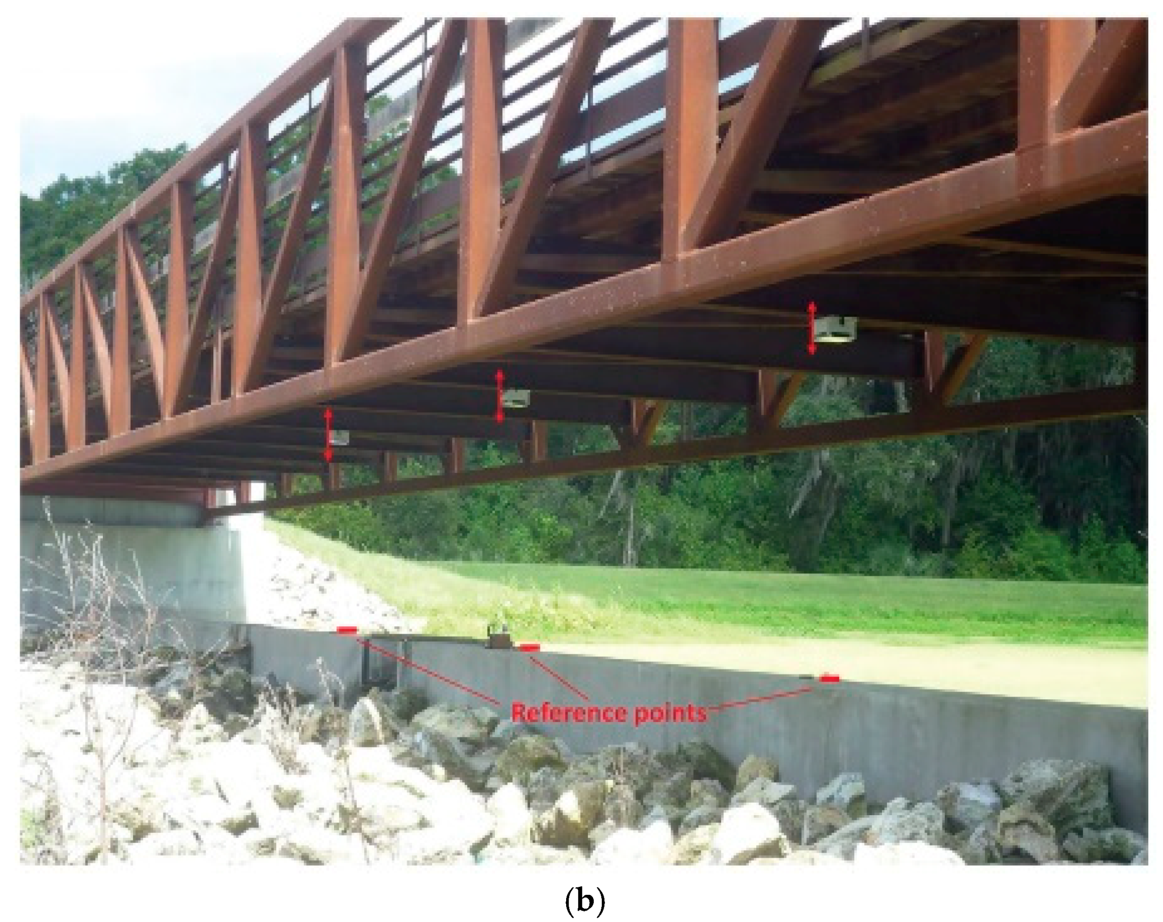
| 2.4-GHz Doppler radar [64] | Active backscattering | 2016 | Pedestrian bridge | Forced | 2.48 m | <1 mm |
| 2.4-GHz Doppler radars arranged as a wireless network [69] | Active backscattering | 2019 | Pedestrian/car bridge | Forced | 4.52 m | <1 mm |
| 5.8-GHz Doppler radar [70] | Passive backscattering (non-adaptive displ. calibration algorithm) | 2020 | Traffic light structure | Forced | 6 m | <1 cm |
| 5.8-GHz Doppler radar [71] | Passive backscattering (adaptive displ. calibration algorithms) | 2020 | Traffic light structure | Forced | 6 m | <1 cm |
| 5.8-GHz Doppler radars arranged as an array [72] | Passive backscattering | 2021 | Traffic light structure | Forced & ambient vibration | 6 m | <1 cm |
| 5.8-GHz/24-GHz Doppler radar [28] | Passive backscattering | 2016 | Wind turbine | Forced | Rotor diameter: 47 m/3.7 m | - |
| 5.8-GHz Doppler radar [94] | Passive backscattering | 2021 | Wind turbine | Forced | Rotor diameter: 111 m | - |
Publisher’s Note: MDPI stays neutral with regard to jurisdictional claims in published maps and institutional affiliations. |
© 2021 by the authors. Licensee MDPI, Basel, Switzerland. This article is an open access article distributed under the terms and conditions of the Creative Commons Attribution (CC BY) license (https://creativecommons.org/licenses/by/4.0/).
Share and Cite
Rodrigues, D.V.Q.; Li, C. A Review on Low-Cost Microwave Doppler Radar Systems for Structural Health Monitoring. Sensors 2021, 21, 2612. https://doi.org/10.3390/s21082612
Rodrigues DVQ, Li C. A Review on Low-Cost Microwave Doppler Radar Systems for Structural Health Monitoring. Sensors. 2021; 21(8):2612. https://doi.org/10.3390/s21082612
Chicago/Turabian StyleRodrigues, Davi V. Q., and Changzhi Li. 2021. "A Review on Low-Cost Microwave Doppler Radar Systems for Structural Health Monitoring" Sensors 21, no. 8: 2612. https://doi.org/10.3390/s21082612
APA StyleRodrigues, D. V. Q., & Li, C. (2021). A Review on Low-Cost Microwave Doppler Radar Systems for Structural Health Monitoring. Sensors, 21(8), 2612. https://doi.org/10.3390/s21082612