
Towards the Autonomy: Control Systems for the Ship in Confined and Open Waters


Abstract
1. Introduction
- The first area is an autonomous calculation of the optimal trajectory also known as ships autonomous navigation [1,2,3,4,5]. Generating automatic trajectories for navigational maps, that include harbor infrastructure, like piers, was partially described in References [6,7,8]. In Reference [9], a novel three-step approach for WSL (Water-Shore Line) detection is, therefore, proposed to solve this problem through the information of an image sequence. Firstly, the initial line segment pool is built by the line segment detector (LSD) algorithm.
- Verification of the proposed control algorithms should take into consideration safety at sea rules, like in Reference [10]. In Reference [11], analysis of the autonomous ship is explored, and system-theoretic process analysis (STPA) and the functional resonance analysis method (FRAM) are identified as the most representative new methods that can be used for hazard analysis of autonomous ships.
- The four area is a concept of autonomous ship control for both cruising and maneuvering speeds. For example, one can refer to the project called Advanced Autonomous Waterborne Applications Initiative (AAWA) created by Rolls-Royce and Kongsberg, described in References [15,16]. Project of the autonomous transport system applicable for the coastal waters and areas beyond the inlands is described also in References [17,18].
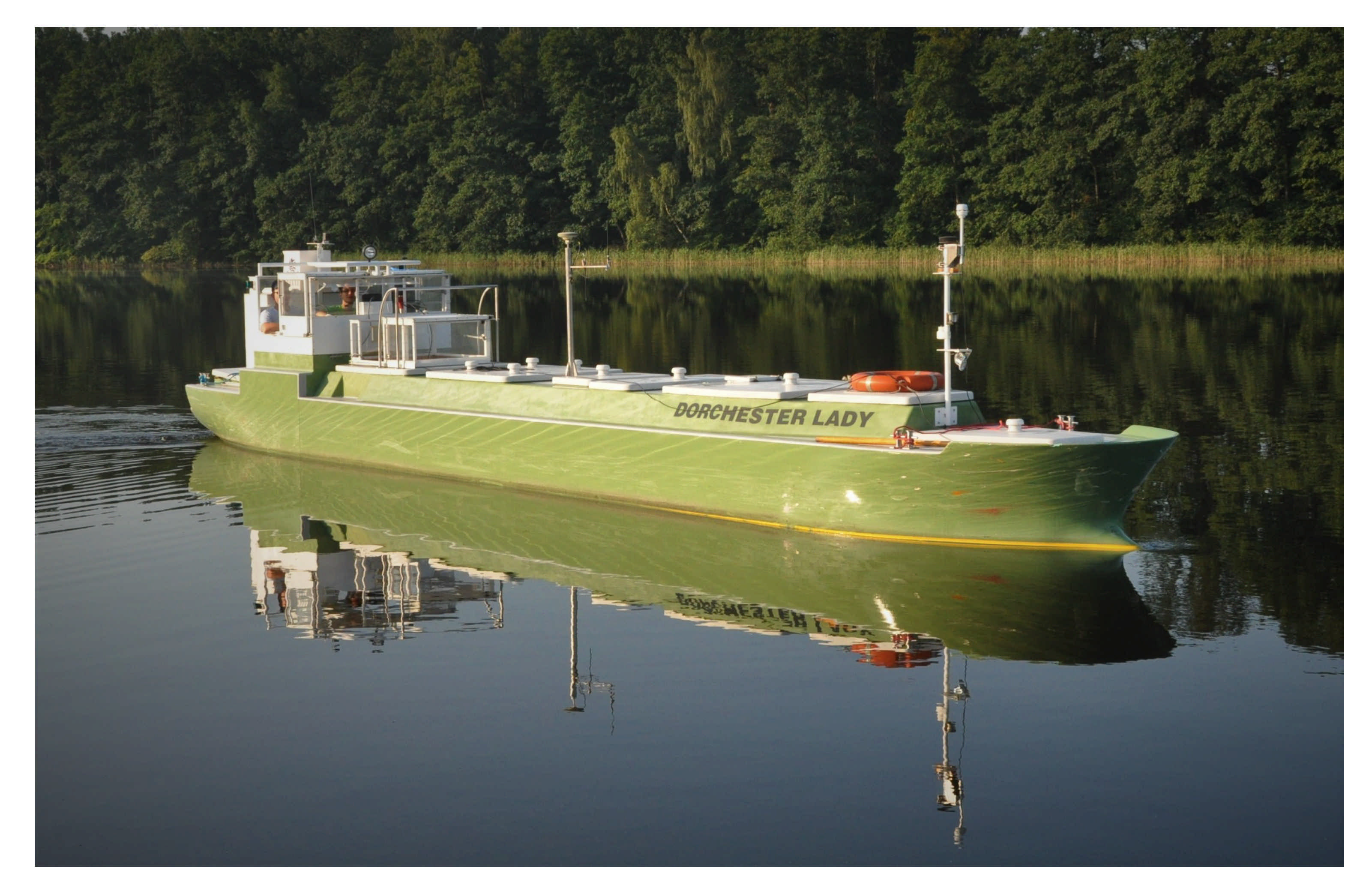
2. Training Ship
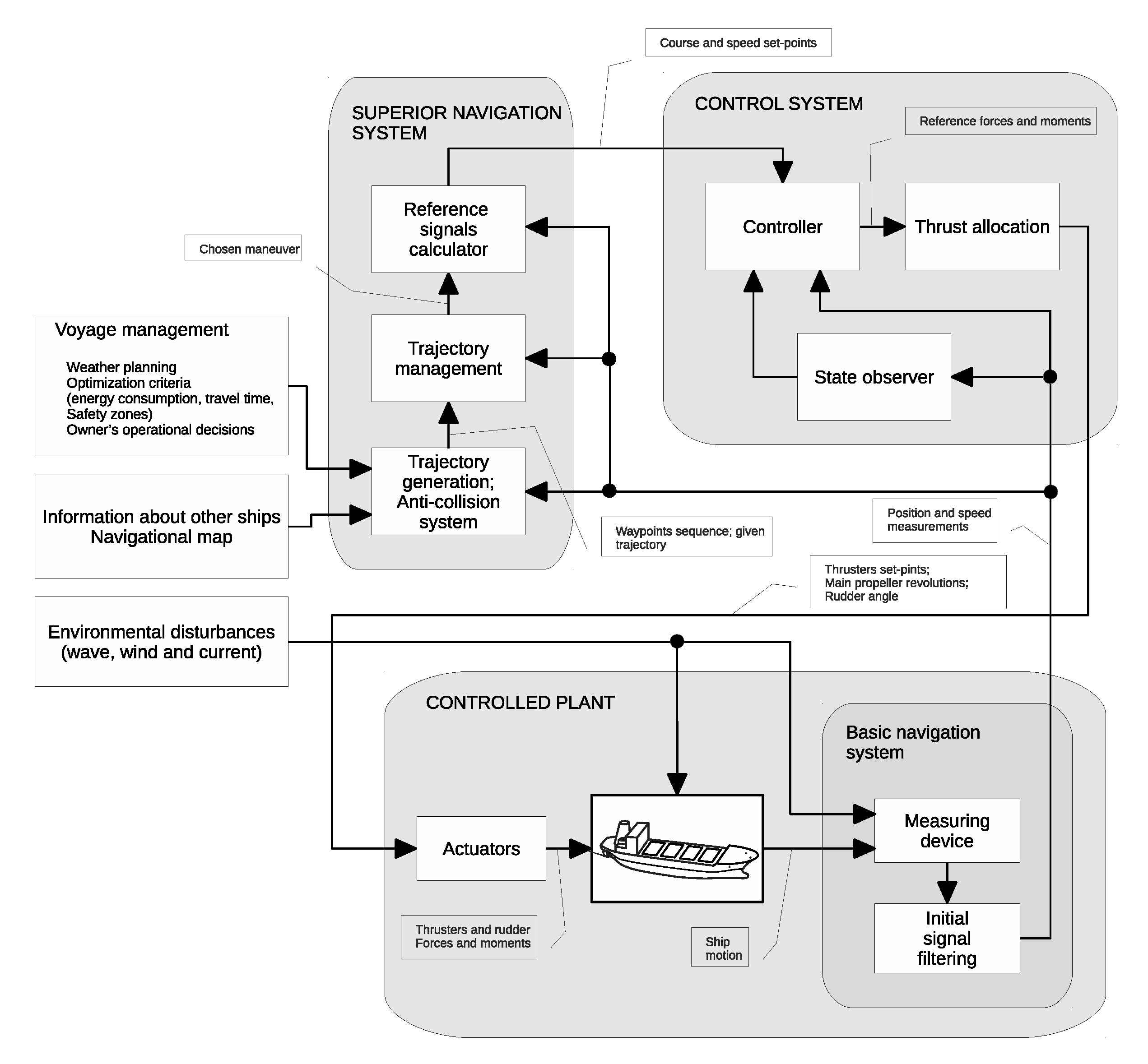
3. Automation of the Ship Motion Control Processes
- –
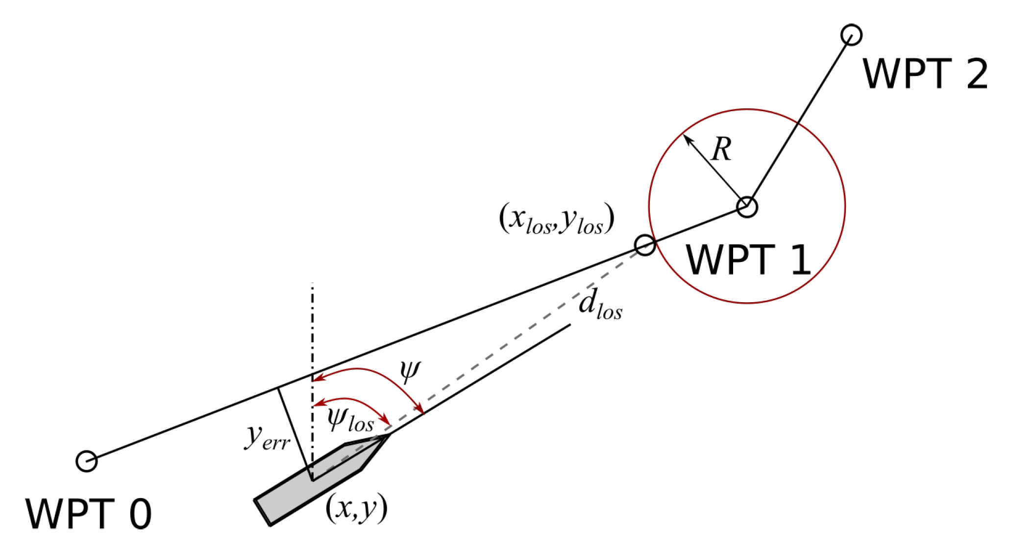
- Supervisory navigation system—where the safe trajectory is generated based on the waypoints sequence, voyage management data, and information about other ships moving in the vicinity, taking into account International Regulations for Preventing Collisions at Sea (COLREG).
- –
- Control system—where, based on the course and speed reference signals, desired actuators’ commands are computed. In this subsystem, the controller cooperates with the state observer and thrust allocation system for low speed multidimensional control.
- –
- Controlled plant—ship equipped with controllable actuators and measurement devices.
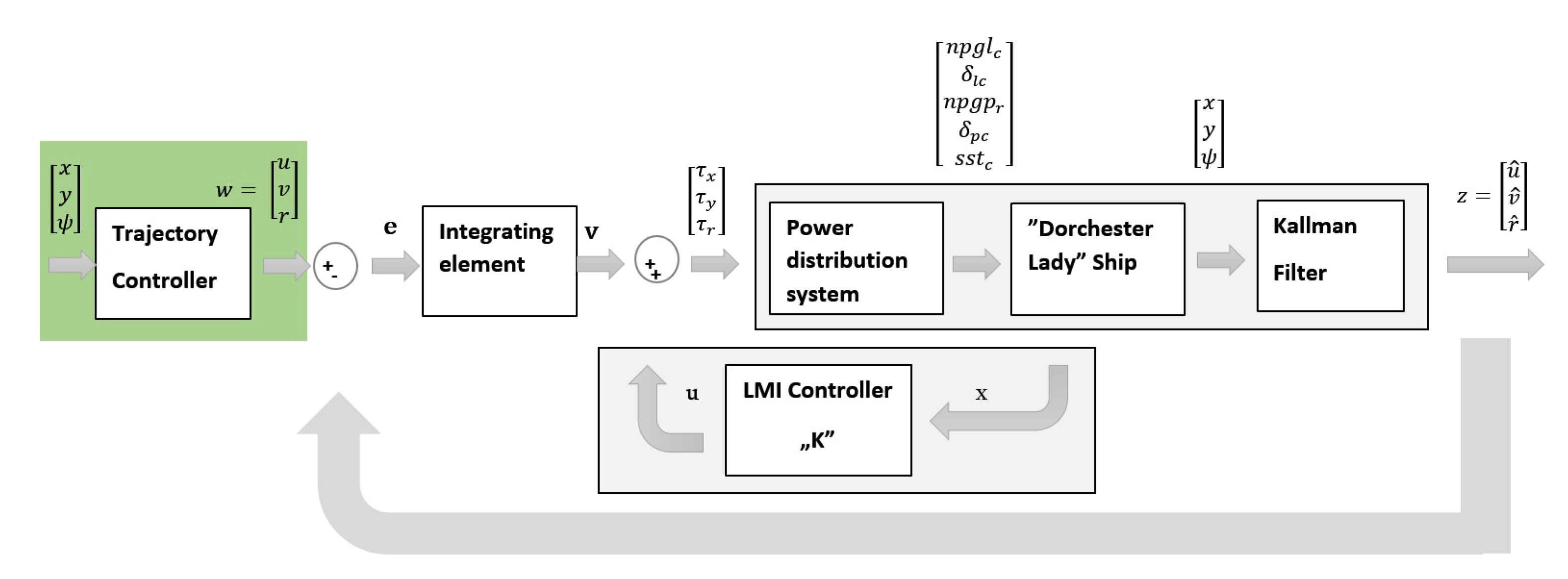
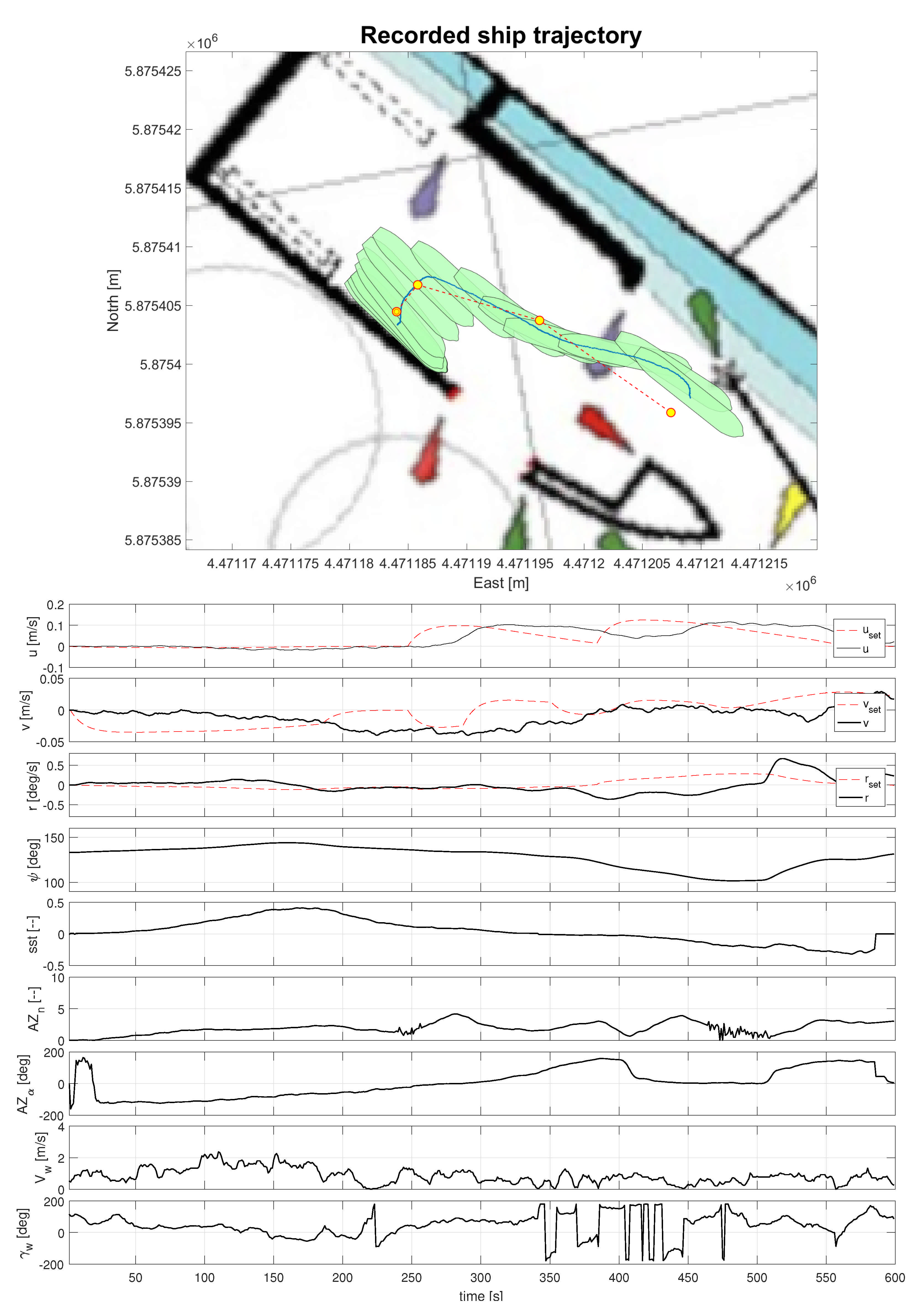
3.1. Multidimensional Control of Autonomous Ship Maneuvering in Port
- -
- stationary Kalman filter system [40] (this system is used for velocities estimation), because “Dorchester Lady” ship model was not equipped with instruments for measuring linear velocities and thus, the need exists for Kalman filter system,
- -
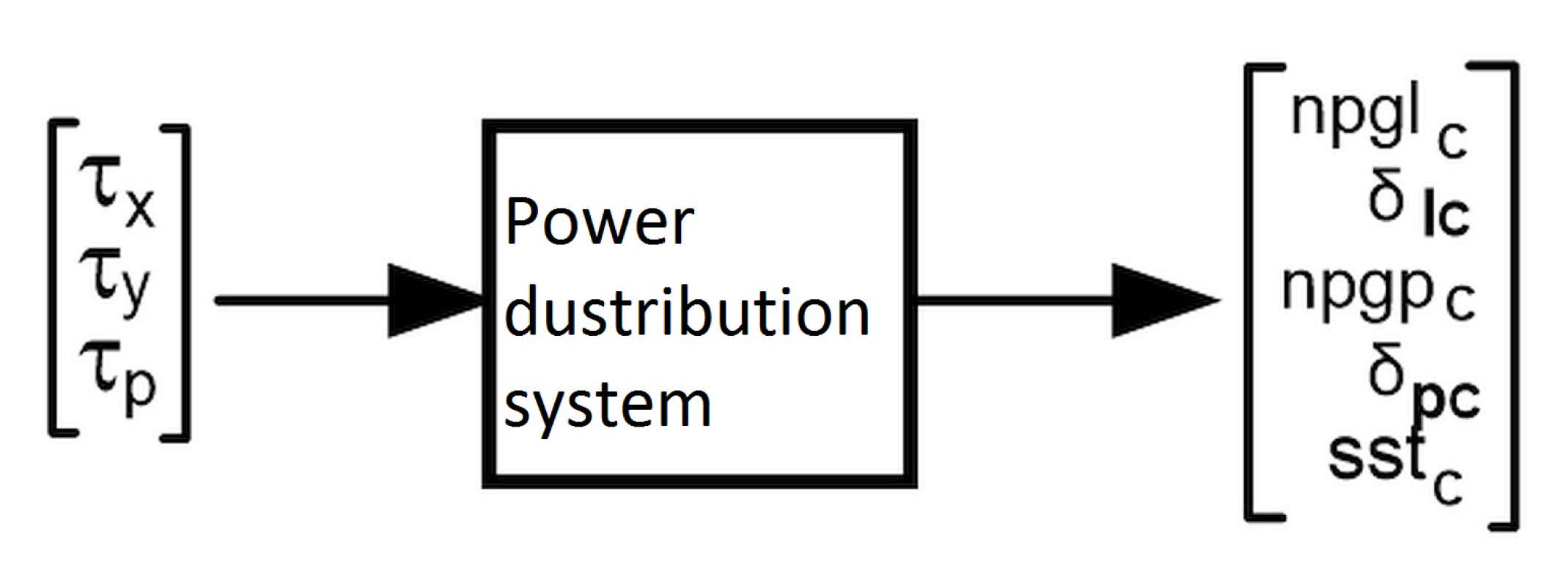
- thrust allocation system used for calculating three components of vector:
- -
- decision variable vector (unknown) x, ,
- -
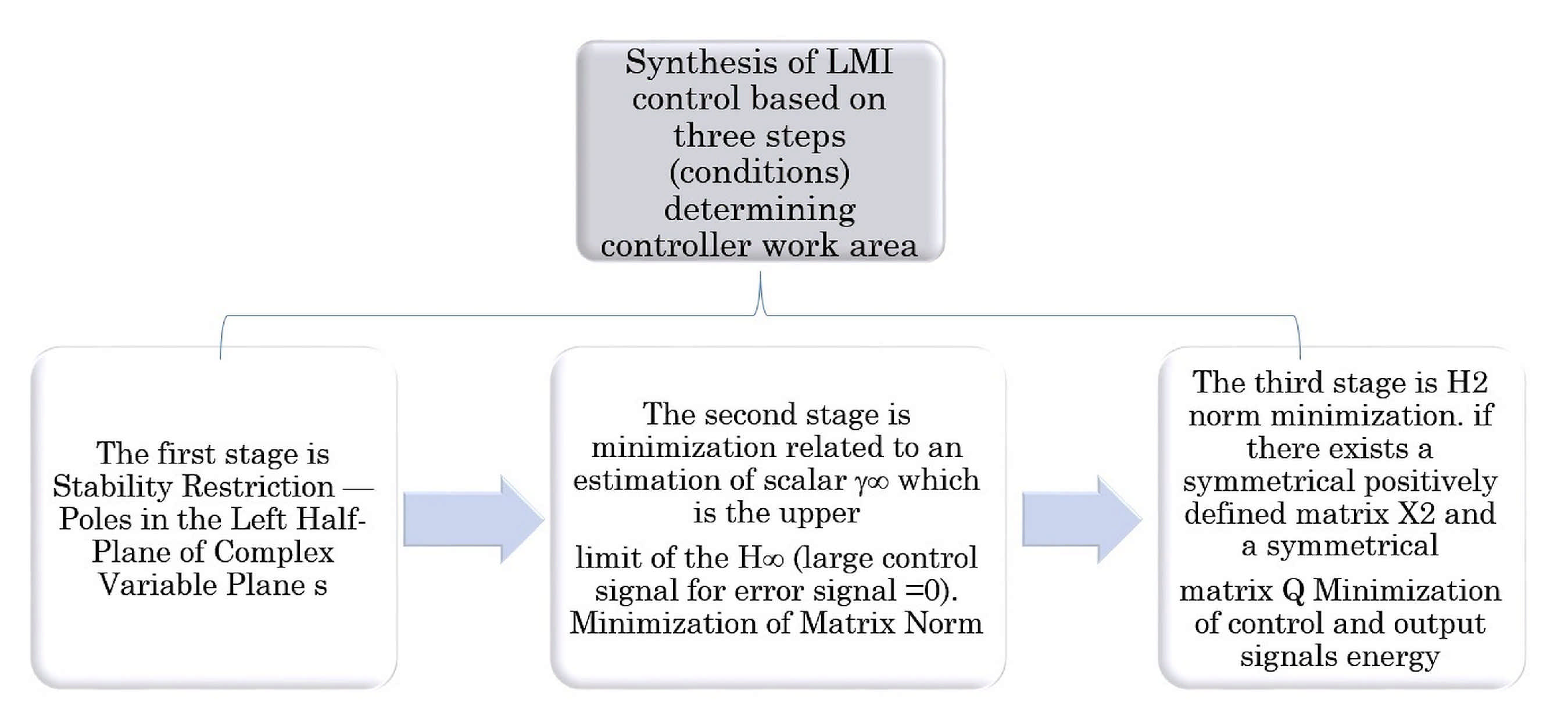
- matrices marked as are real and symmetrical, where symmetrical matrix has the form of: for , and
- -
- the term “” means that the matrix is positively defined.
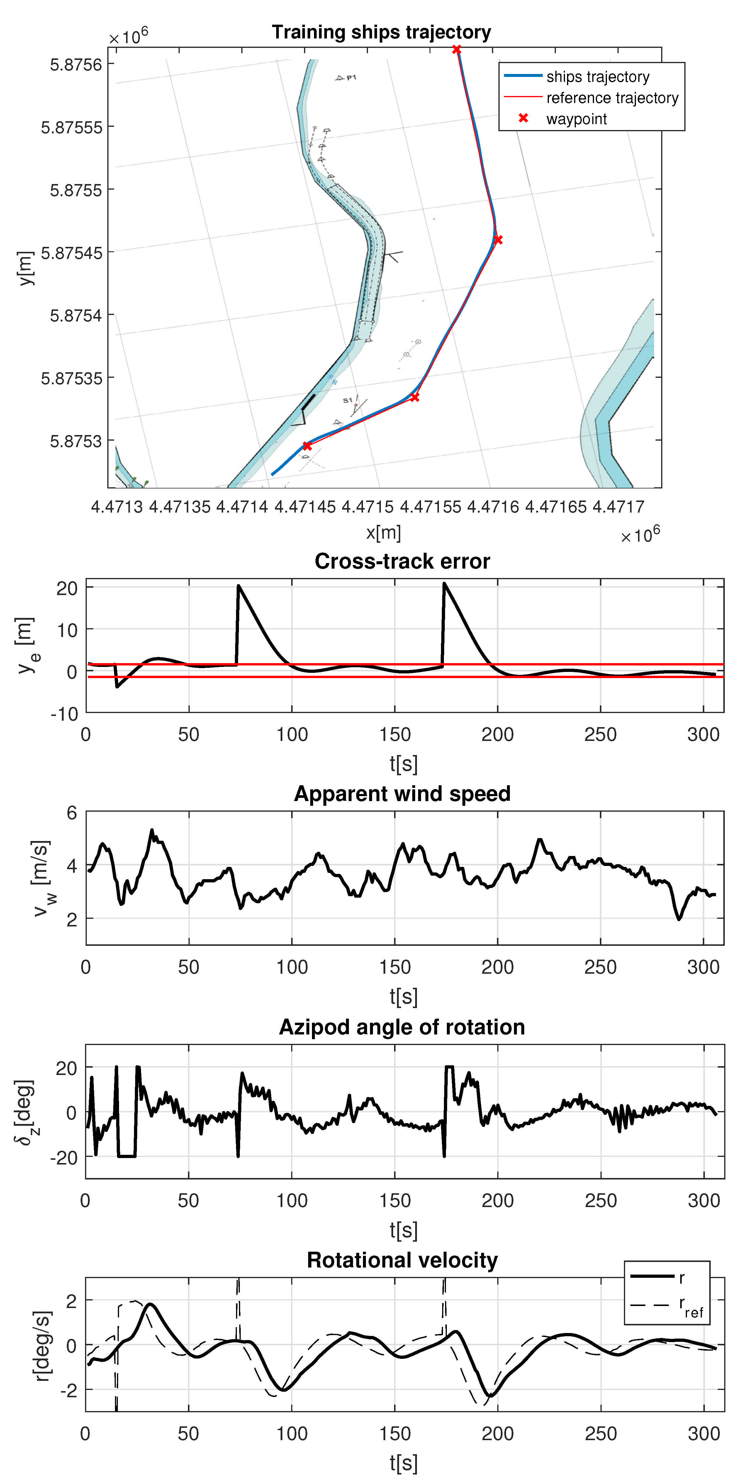
3.2. Autonomous Ship Open Water Trajectory Tracking
- -
- —predicted next state;
- -
- —predicted current state;
- -
- —current control signal (azipod angle of rotation );
- -
- —current output signal (rotational velocity r).
- -
- ,—output signal change and error weight coefficients;
- -
- —reference, output, and control signal change values;
- -
- —signal value at time moment predicted in k time moment;
- -
- —prediction and control horizon lengths.
4. Essential Components Arrangement of the Autonomous Training Ship
- –
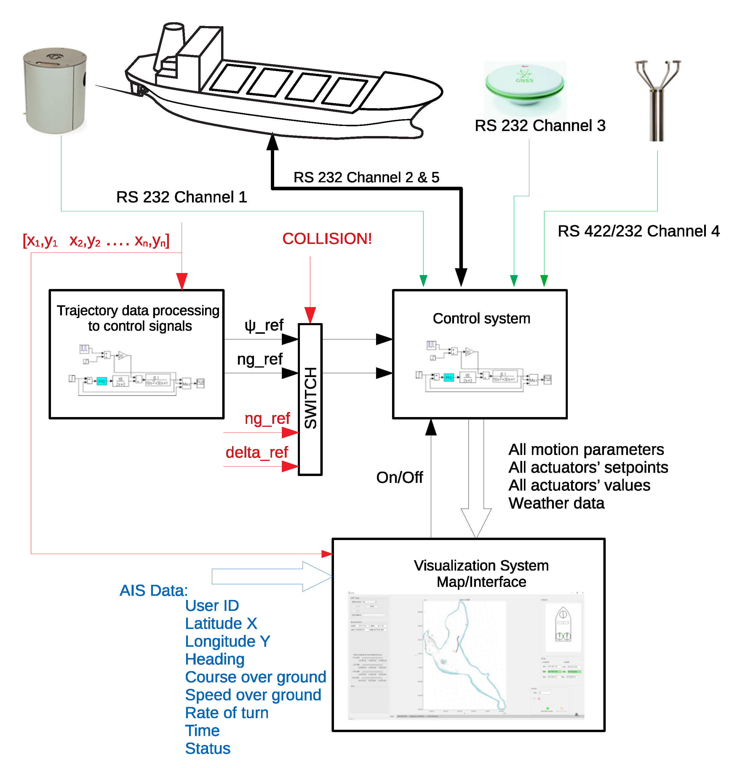
- trajectory tracking—in which it cooperates with safe trajectory generation subsystem. After defining a safe and achievable trajectory, reference waypoints are transformed into reference control signals—reference course and main engine set-points.
- –
- maneuvering mode in a restricted area—where ship movement is defined by the set of waypoints and desired ship’s heading. This is the way the ship moves, e.g., when approaching the quay. Surge, sway, and yaw are controlled. Operation in this mode requires not only azipods usage; bow and azimuth thrusters are also activated to perform necessary motions.
- –
- Last Minute Maneuver (LMM) for collision avoidance—where safe trajectory generation subsystem defines thrusters’ setpoints allowing for collision avoidance or minimizing its effects (switch input signals marked by red in Figure 7).
HMI for Research and Documentation Purpose
- –
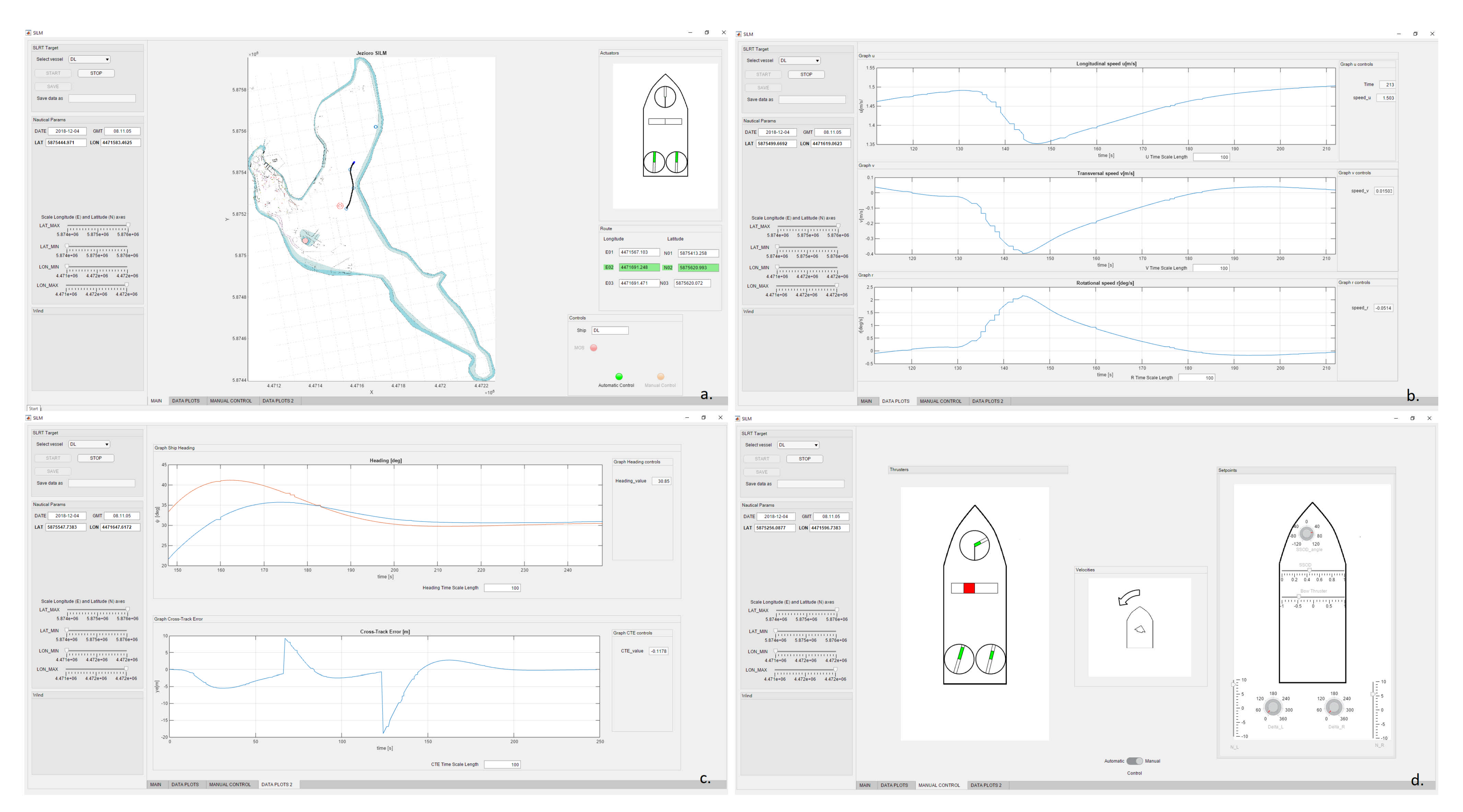
- Autonomous ship selection option: after choosing a ship to control, in panel “Actuators” thrusters configuration corresponding to those actually installed on the particular training ship is presented. Their setpoints are updated and visualized every second.
- –
- “Start”, “Stop”, and “Save” buttons: they are available depending on the state of the SLRT controller software and allow the user to start and stop application and save data from its memory.
- –
- “Nautical Params” panel: date, time, and position from GPS receiver are displayed together with sliders allowing for chart scaling.
- –
- “Route” panel: data of three consecutive waypoints are displayed there—previous, current (highlighted in green), and next.
- –
- “Controls” panel: there are grouped controls indicating ship’s operating mode (automatic or manual control) and whether LMM maneuver is realized, while the name of selected ship is written in the text box.
- –
- Electronic chart: where waypoints are presented together with measured ship’s trajectory.
5. Results
6. Discussion
7. Conclusions
Author Contributions
Funding
Institutional Review Board Statement
Informed Consent Statement
Data Availability Statement
Acknowledgments
Conflicts of Interest
Abbreviations
| AAWA | Advanced Autonomous Waterborne Applications Initiative |
| AIS | Automatic Identification System |
| ATS | Autonomous Training Ship |
| AVAL | Autonomous Vessel with an Air Look |
| COLREG | International Regulations for Preventing Collisions at Sea |
| GPS | Global Positioning System |
| DWT | Deadweight Tonnage |
| ECDIS | Electronic Chart Display and Information System |
| FRAM | Functional Resonance Analysis Method |
| GUI | Graphical User Interface |
| HMI | Human-Machine Interface |
| IMO | International Maritime Organization |
| LMI | Linear Matrix Inequalities |
| LMM | Last Minute Maneuver |
| LNG | Liquefied Natural Gas |
| LOS | Line-of-sight |
| MASS | Marine Autonomous Surface Ship |
| MPC | Model Predictive Control |
| NMEA | National Marine Electronics Association |
| PROMARE | Promoting Marine Research and Exploration |
| RTK | Real Time Kinematic |
| SLRT | Simulink Real-Time Toolbox |
| STPA | System-Theoretic Process Analysis |
| WGS | World Geodetic System |
| WPT | Waypoint |
| WSL | Water-Shore Line |
| XTE | Cross-track error |
References
- Perera, L.P.; Ferrari, V.; Santos, F.P.; Hinostroza, M.A.; Soares, C.G. Experimental evaluations on ship autonomous navigation and collision avoidance by intelligent guidance. IEEE J. Ocean. Eng. 2014, 40, 374–387. [Google Scholar] [CrossRef]
- Pietrzykowski, Z.; Wolejsza, P.; Borkowski, P. Decision support in collision situations at sea. J. Navig. 2017, 70, 447. [Google Scholar] [CrossRef]
- Lazarowska, A. A discrete planning approach in collision avoidance for smart ships. Procedia Comput. Sci. 2020, 176, 380–389. [Google Scholar] [CrossRef]
- Lazarowska, A. Parameters influence on the performance of an Ant algorithm for safe ship trajectory planning. In Proceedings of the 2015 IEEE 2nd International Conference on Cybernetics (CYBCONF), Gdynia, Poland, 24–26 June 2015; pp. 140–145. [Google Scholar]
- Lisowski, J. Sensitivity of safe trajectory in a game environment on inaccuracy of radar data in autonomous navigation. Sensors 2019, 19, 1816. [Google Scholar] [CrossRef]
- Xue, Y.; Clelland, D.; Lee, B.; Han, D. Automatic simulation of ship navigation. Ocean. Eng. 2011, 38, 2290–2305. [Google Scholar] [CrossRef]
- Karbowska-Chilinska, J.; Koszelew, J.; Ostrowski, K.; Kuczynski, P.; Kulbiej, E.; Wolejsza, P. Beam search Algorithm for ship anti-collision trajectory planning. Sensors 2019, 19, 5338. [Google Scholar] [CrossRef]
- Mohamed-Seghir, M. The fuzzy properties of the ship control in collision situations. In Proceedings of the 2017 IEEE International Conference on INnovations in Intelligent SysTems and Applications (INISTA), Gdynia, Poland, 3–5 July 2017; pp. 107–112. [Google Scholar]
- Zou, X.; Xiao, C.; Zhan, W.; Zhou, C.; Xiu, S.; Yuan, H. A Novel Water-Shore-Line Detection Method for USV Autonomous Navigation. Sensors 2020, 20, 1682. [Google Scholar] [CrossRef]
- Xue, J.; Van Gelder, P.; Reniers, G.; Papadimitriou, E.; Wu, C. Multi-attribute decision-making method for prioritizing maritime traffic safety influencing factors of autonomous ships’ maneuvering decisions using grey and fuzzy theories. Saf. Sci. 2019, 120, 323–340. [Google Scholar] [CrossRef]
- Chae, C.J.; Kim, M.; Kim, H.J. A Study on Identification of Development Status of MASS Technologies and Directions of Improvement. Appl. Sci. 2020, 10, 4564. [Google Scholar] [CrossRef]
- Haseltalab, A.; Negenborn, R.R. Model predictive maneuvering control and energy management for all-electric autonomous ships. Appl. Energy 2019, 251, 113308. [Google Scholar] [CrossRef]
- Al-Falahi, M.D.; Tarasiuk, T.; Jayasinghe, S.G.; Jin, Z.; Enshaei, H.; Guerrero, J.M. AC ship microgrids: Control and power management optimization. Energies 2018, 11, 1458. [Google Scholar] [CrossRef]
- Huotari, J.; Ritari, A.; Ojala, R.; Vepsäläinen, J.; Tammi, K. Q-Learning Based Autonomous Control of the Auxiliary Power Network of a Ship. IEEE Access 2019, 7, 152879–152890. [Google Scholar] [CrossRef]
- Rolls-Royce. The Next Steps of Remote and Autonomous Ships. 2018. Available online: https://www.rolls-royce.com/~/media/Files/R/Rolls-Royce/documents/customers/marine/ship-intel/aawa-whitepaper–210616.pdf (accessed on 13 January 2020).
- Kongsberg. Autonomous Ship Project, Key Facts about YARA Birkeland. 2020. Available online: https://www.km.kongsberg.com/ks/web/nokbg0240.nsf/AllWeb/%4B8113B707A50A4FC125811D00407045 (accessed on 13 January 2020).
- Łebkowski, A. Design of an autonomous transport system for coastal areas. TransNav Int. J. Mar. Navig. Saf. Sea Transp. 2018, 12, 117–124. [Google Scholar] [CrossRef]
- Łebkowski, A. The Concept of Autonomous Coastal Transport. TransNav Int. J. Mar. Navig. Saf. Sea Transp. 2017, 351–358. [Google Scholar]
- IMO London. Regulatory Scoping Exercise for the Use of Maritime Autonomous Surface Ships. MSC 2018, 12. Available online: https://www.setfords.co.uk/wp-content/uploads/MSC9955.pdf (accessed on 13 January 2020).
- Baldauf, M.; Fischer, S.; Kitada, M.; Mehdi, R.; Al-Quhali, M.; Fiorini, M. Merging conventionally navigating ships and MASS-Merging VTS, FOC and SCC? TransNav Int. J. Mar. Navig. Saf. Sea Transp. 2019, 13, 495–501. [Google Scholar] [CrossRef]
- Wright, R.G. Intelligent autonomous ship navigation using multi-sensor modalities. TransNav Int. J. Mar. Navig. Saf. Sea Transp. 2019, 13, 503–510. [Google Scholar] [CrossRef]
- Kobyliński, L. Smart ships–autonomous or remote controlled? Zesz. Nauk. Akad. Morskiej Szczecinie 2018, 53, 28–34. [Google Scholar]
- Wang, L.; Wu, Q.; Liu, J.; Li, S.; Negenborn, R.R. State-of-the-art research on motion control of maritime autonomous surface ships. J. Mar. Sci. Eng. 2019, 7, 438. [Google Scholar] [CrossRef]
- Zhang, X.; Wang, C.; Liu, Y.; Chen, X. Decision-making for the autonomous navigation of maritime autonomous surface ships based on scene division and deep reinforcement learning. Sensors 2019, 19, 4055. [Google Scholar] [CrossRef]
- Geng, X.; Wang, Y.; Wang, P.; Zhang, B. Motion plan of maritime autonomous surface ships by dynamic programming for collision avoidance and speed optimization. Sensors 2019, 19, 434. [Google Scholar] [CrossRef]
- Alfheim, H.L.; Muggerud, K.; Breivik, M.; Brekke, E.F.; Eide, E.; Engelhardtsen, Ø. Development of a dynamic positioning system for the revolt model ship. IFAC-PapersOnLine 2018, 51, 116–121. [Google Scholar] [CrossRef]
- Hu, X.; Du, J.; Sun, Y. Robust adaptive control for dynamic positioning of ships. IEEE J. Ocean. Eng. 2017, 42, 826–835. [Google Scholar] [CrossRef]
- Li, W.; Sun, Y.; Chen, H.; Wang, G. Model predictive controller design for ship dynamic positioning system based on state-space equations. J. Mar. Sci. Technol. 2017, 22, 426–431. [Google Scholar] [CrossRef]
- Tomera, M. Path Controller for Ships with Switching Approach. In Advanced, Contemporary Control; Springer: Berlin/Heidelberg, Germany, 2020; pp. 1519–1530. [Google Scholar]
- Wang, S.; Wang, L.; Qiao, Z.; Li, F. Optimal robust control of path following and rudder roll reduction for a container ship in heavy waves. Appl. Sci. 2018, 8, 1631. [Google Scholar] [CrossRef]
- Zhang, G.; Deng, Y.; Zhang, W. Robust neural path-following control for underactuated ships with the DVS obstacles avoidance guidance. Ocean Eng. 2017, 143, 198–208. [Google Scholar] [CrossRef]
- Liu, Y.; Bu, R.; Gao, X. Ship trajectory tracking control system design based on sliding mode control algorithm. Pol. Marit. Res. 2018, 25, 26–34. [Google Scholar] [CrossRef]
- Zhu, G.; Du, J. Global robust adaptive trajectory tracking control for surface ships under input saturation. IEEE J. Ocean Eng. 2018, 45, 442–450. [Google Scholar] [CrossRef]
- Ma, Y.; Zhu, G.; Li, Z. Error-driven-based nonlinear feedback recursive design for adaptive NN trajectory tracking control of surface ships with input saturation. IEEE Intell. Transp. Syst. Mag. 2019, 11, 17–28. [Google Scholar] [CrossRef]
- Abdelaal, M.; Fränzle, M.; Hahn, A. Nonlinear Model Predictive Control for trajectory tracking and collision avoidance of underactuated vessels with disturbances. Ocean Eng. 2018, 160, 168–180. [Google Scholar] [CrossRef]
- Zhou, X.; Wu, Y.; Huang, J. MPC-based path tracking control method for USV. In Proceedings of the 2020 Chinese Automation Congress (CAC), Xi’an, China, 30 November–2 December 2020; pp. 1669–1673. [Google Scholar]
- Gierusz, W. Simulation model of the LNG carrier with podded propulsion, Part II: Full model and experimental results. Ocean Eng. 2016, 123, 28–44. [Google Scholar] [CrossRef]
- Miller, A. Identification of a multivariable incremental model of the vessel. In Proceedings of the 2016 21st International Conference on Methods and Models in Automation and Robotics (MMAR), Miȩdzyzdroje, Poland, 29 August–1 September 2016; pp. 218–224. [Google Scholar]
- Miller, A. Interaction Forces Between Two Ships During Underway Replenishment. J. Navig. 2016, 69, 1197. [Google Scholar] [CrossRef]
- Mansouri, M.M.; Mohamed-Seghir, M.M.; Nounou, H.N.; Nounou, M.N.; Abu-Rub, H.A. Bayesian methods for time-varying state and parameter estimation in induction machines. Int. J. Adapt. Control. Signal Process. 2015, 29, 905–924. [Google Scholar] [CrossRef]
- Gierusz, W.; Rybczak, M. Effectiveness of Multidimensional Controllers Designated to Steering of the Motions of Ship at Low Speed. Sensors 2020, 20, 3533. [Google Scholar] [CrossRef]
- Boyd, S.; El Ghaoui, L.; Feron, E.; Balakrishnan, V. Linear Matrix Inequalities in System and Control Theory; SIAM: Philadelphia, PA, USA, 1994. [Google Scholar]
- Rybczak, M. Improvement of control precision for ship movement using a multidimensional controller. Autom. Cas. Autom. Mjer. Elektron. Racun. Komun. 2018, 59, 63–70. [Google Scholar] [CrossRef]
- Fossen, T.I.; Breivik, M.; Skjetne, R. Line-of-sight path following of underactuated marine craft. IFAC Proc. Vol. 2003, 36, 211–216. [Google Scholar] [CrossRef]
- Japan NYK. NYK Has Conducted the World’s First ’Maritime Autonomous Surface Ships. 2020. Available online: https://www.nyk.com/english/news/2019/2019093001.html (accessed on 13 February 2020).


| Parameter | “Dorchester Lady” |
|---|---|
| Length overall L [m] | 11.55 |
| Breadth B [m] | 1.80 |
| Draft T [m] | 0.50 |
| Displacement D [T] | 8.21 |
| Max. speed u [kn] | 4.1 |
| Waypoint No. | Longitude [m] | Latitude [m] | Heading [deg] |
|---|---|---|---|
| 1 | 4,471,184.04 | 5,875,404.47 | 132.50 |
| 2 | 4,471,185.81 | 5,875,406.74 | 132.50 |
| 3 | 4,471,196.23 | 5,875,403.71 | 125.00 |
| 4 | 4,471,207.42 | 5,875,395.87 | 130.00 |
| Waypoint No. | Longitude [m] | Latitude [m] | Heading [deg] |
|---|---|---|---|
| 1 | 4,471,452.27 | 5,875,295.22 | 047.0 |
| 2 | 4,471,537.91 | 5,875,334.05 | 065.0 |
| 3 | 4,471,604.28 | 5,875,459.39 | 025.0 |
| 4 | 4,471,571.31 | 5,875,611.15 | 350.0 |
Publisher’s Note: MDPI stays neutral with regard to jurisdictional claims in published maps and institutional affiliations. |
© 2021 by the authors. Licensee MDPI, Basel, Switzerland. This article is an open access article distributed under the terms and conditions of the Creative Commons Attribution (CC BY) license (http://creativecommons.org/licenses/by/4.0/).
Share and Cite
Miller, A.; Rybczak, M.; Rak, A. Towards the Autonomy: Control Systems for the Ship in Confined and Open Waters. Sensors 2021, 21, 2286. https://doi.org/10.3390/s21072286
Miller A, Rybczak M, Rak A. Towards the Autonomy: Control Systems for the Ship in Confined and Open Waters. Sensors. 2021; 21(7):2286. https://doi.org/10.3390/s21072286
Chicago/Turabian StyleMiller, Anna, Monika Rybczak, and Andrzej Rak. 2021. "Towards the Autonomy: Control Systems for the Ship in Confined and Open Waters" Sensors 21, no. 7: 2286. https://doi.org/10.3390/s21072286
APA StyleMiller, A., Rybczak, M., & Rak, A. (2021). Towards the Autonomy: Control Systems for the Ship in Confined and Open Waters. Sensors, 21(7), 2286. https://doi.org/10.3390/s21072286