Article

Electromechanical Response of Smart Ultra-High Performance Concrete under External Loads Corresponding to Different Electrical Measurements

1
Department of Civil and Environmental Engineering, SEJONG University, 209, Neungdong-ro, Gwangjin-gu, Seoul 05006, Korea
2
Department of Civil Engineering, Hanoi University of Mining and Geology, Hanoi 100000, Vietnam
*
Author to whom correspondence should be addressed.
Sensors 2021, 21(4), 1281; https://doi.org/10.3390/s21041281
Submission received: 12 January 2021 / Revised: 4 February 2021 / Accepted: 8 February 2021 / Published: 11 February 2021
(This article belongs to the Section Sensor Materials)

Abstract

:
This study investigated the electromechanical response of smart ultra-high-performance concretes (smart UHPCs), containing fine steel slag aggregates (FSSAs) and steel fibers as functional fillers, under external loads corresponding to different measurement methods. Regardless of different measurement methods of electrical resistance, the smart UHPCs under compression showed a clear reduction in their electrical resistivity. However, under tension, their electrical resistivity measured from direct current (DC) measurement decreased, whereas that from alternating current (AC) measurement increased. This was because the electrical resistivity, from DC measurement, of smart UHPCs was primarily dependent on fiber crack bridging, whereas that from AC measurement was dependent on tunneling effects.

1. Introduction

Smart construction materials (SCMs) with self-sensing capacity have great potential in the field of structural health monitoring (SHM) systems for civil infrastructures and buildings [1]. Much research has been extensively conducted to retain the self-sensing capacity of SCMs, even after initial cracking, by adding short steel and/or polyvinyl alcohol (PVA) fibers to mortar matrices under tension [2,3,4,5]. Strain-hardening cementitious composites (SHCCs), types of SCM containing short steel and/or PVA fiber, as functional fillers, have clearly demonstrated self-sensing capacity in the tensile strain-hardening region and generated multiple microcracks [4,5]. Both direct current (DC) and alternative current (AC) measurement methods have been used to investigate the electromechanical responses of strain-hardening steel-fiber-reinforced cementitious composites (SH-SFRCs) and engineered cementitious composites (ECCs) [5,6,7,8].
The electrical resistance (or real impedance) of SH-SFRCs decreased [2,3,4,5,6,7], whereas that of ECCs with polyvinyl alcohol (PVA) fibers increased as the tensile strain of them increased [5,9]. The difference in the electromechanical responses of SH-SFRCs and ECCs was based on the type of fiber. In addition, the reported electromechanical responses were measured from different (DC or AC) measurement methods [3,5]. The DC measurement delivers constant electrical currents to SCMs, but it requires considerable time to stabilize electrical polarization. On the other hands, AC measurement does not require considerable polarization time; thus, it quickly measures the electrical impedance of SCMs [1,10]. Although there are many studies in the literature reporting the difference between DC and AC measurements, it is difficult to find a suitable reference directly comparing the electrical resistance (or impedance) of SCMs corresponding to different DC and AC measurements.
Carbon black, granulated blast furnace slag, milled glass fibers, and fine steel slag aggregates have been utilized as additional fillers to further enhance the self-sensing capacity of SH-SFRCs [7,11,12,13]. The SH-SFRCs containing fine steel slag aggregates (FSSAs) instead of silica sand (i.e., smart ultra-high-performance concretes (smart UHPCs)) have demonstrated noticeably enhanced stress self-sensing capacity under compression [8]. However, the influence of different electrical (DC and AC) currents on the measured electromechanical responses of smart UHPCs under external loads, has not been investigated yet. In other words, it is not clear if the electromechanical responses of SCMs measured using DC measurement would be identical to those obtained using AC measurement. The electromechanical responses of SCMs under external loads should be investigated and compared under different current sources to find a suitable measurement method for self-strain-, -stress-, and -damage-sensing capabilities of SCMs, because DC and AC have different electron movement.
The self-sensing mechanisms of SCMs containing the functional fillers under external loads can be classified corresponding to the type of functional fillers (particle- or fiber- type). The SCMs containing particle-type functional fillers (e.g., nickel powder, carbon black, and steel slag aggregates) have exhibited sensing mechanisms that are primarily based on a conductive network or tunneling effect, regardless of the current sources [8,14,15]. On the other hand, the self-sensing mechanisms of SCMs containing fiber-type functional fillers (e.g., Ni nanowire, carbon, PVA, and steel fibers) are dependent upon loading conditions [3,5,16,17]. Under compression, the self-sensing mechanisms of SCMs containing fiber-type functional fillers are similar to that of those containing particle-type functional fillers [8,17,18]. However, under tension, the self-sensing mechanisms of SCMs were found to be different and closely related to the electrical resistance of their bonded and debonded fiber-matrix interfaces during fiber pullout [19,20,21].
To clarify self-strain-, -damage-, and -stress-sensing mechanisms, as well as to find a more suitable method for the measurement of electromechanical response of smart UHPCs under specific loading conditions, in this study, we investigated the electromechanical responses of smart UHPCs, containing steel fibers and FSSAs as functional fillers, corresponding to different electrical currents (DC or AC) under external loads. The detailed objectives of this study were: (1) to investigate the electromechanical responses of smart UHPCs corresponding to the current sources (DC or AC); (2) to evaluate the self-strain, -damage, and -stress-sensing capacity of smart UHPCs; and (3) to understand the sources of different electromechanical responses of smart UHPCs under external loads corresponding to different (DC or AC) measurement methods.

2. Experimental

Figure 1 illustrates the experimental program designed to investigate the electromechanical responses of smart UHPCs corresponding to different current sources under various loading conditions. Table 1 shows the compositions of the matrices used in the experimental program: Ma is a typical matrix composition using silica sand, whereas Mb replaced 50% of silica sand with fine steel slag aggregates (FSSAs). Table 2 provides the properties of functional fillers, including steel fibers and FSSAs. The length and diameter of steel fibers used for tensile specimens were 30 and 0.3 mm (long smooth), respectively, whereas those for compressive specimens were 6 and 0.2 mm (short smooth), respectively. The content of steel fibers added to the three matrices was 2 vol.% for all specimens. Figure 2 shows the images of functional fillers, including steel fibers and FSSAs, used in the experimental program. The electrical response (resistance or impedance) of smart UHPCs was measured using both direct current (DC) and alternating current (AC) under direct tension and compression.

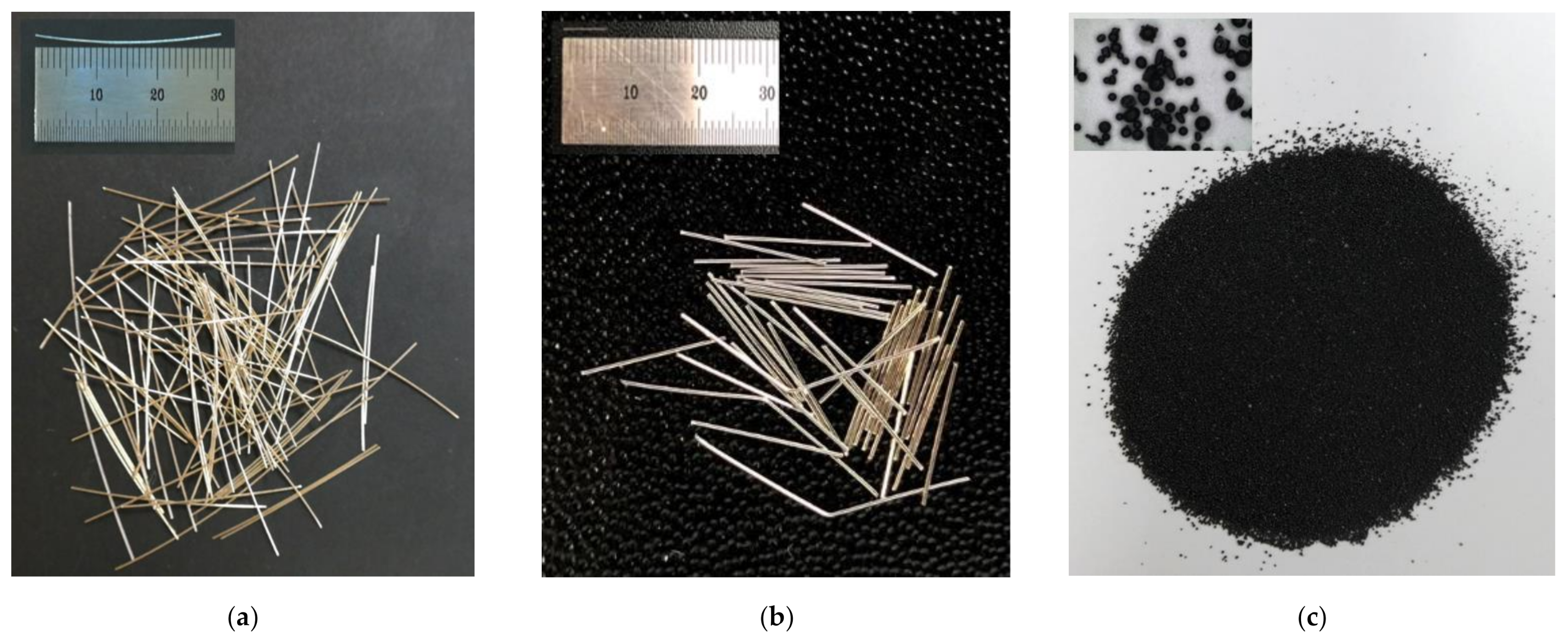
2.1. Materials and Specimen Preparation

Table 1 provided the composition and compressive strength of the two mortar matrices, while Table 2 summarized the properties of the steel fibers (long and short smooth) and FSSAs. The components of all mortar matrices were type 1 cement, silica fume, silica powder, and silica sand. FSSAs were added to only Mb as a partial replacement of silica sands. The average grain diameter of silica sand in all mortar matrices was 0.30 mm. The maximum diameter of ball-shaped FSSAs was 0.39 mm. The compressive strengths of Ma and Mb were measured as 178 and 179 MPa, respectively [12].
A Hobart-type laboratory mixer with a capacity of 20 L was used for mortar mixing. The components of the matrices (including the cement, silica fume, silica powder, and silica sand or/and FSSAs) were first dry-mixed for 5 min, then water was added to the mixture, and the mortar mixture was mixed for 5 min. The superplasticizer was gradually added, followed by further mixing for 5 min. When the workability of mortar matrices was suitable for uniform fiber distribution, then steel fibers were carefully dispersed by hand into the mortar mixtures, and the mixture containing fibers was then mixed for 1 min.
The gauge length of dumbbell-shaped tensile specimens was 100 mm, while the cross-sectional area of the specimens was 25 mm × 50 mm, as shown in Figure 3a. Two layers of steel wire mesh were reinforced at both ends of the specimen to prevent failure outside the gauge length, as shown in Figure 3a. The cubic specimens (50 mm × 50 mm × 50 mm) were prepared, as shown in Figure 3b, to investigate the electromechanical responses of smart UHPCs under compression.
When the mortar mixture showed a suitable workability, steel fibers were added to the mixture and then further mixed for 1 min. The mortar mixture with fibers was then poured into molds. After casting, all specimens were covered with plastic sheets and placed in a laboratory at room temperature (25 °C) and 60% relative humidity for 48 h prior to demolding. After demolding, the specimens were water-cured at 90 °C for three days.
For AC measurement, the tensile specimen was electrically grounded from the steel grip by coating the grip region with epoxy to insulate the electrodes. A copper tape electrode was mounted on the surface of the cured specimens using silver paste as an adhesive (Figure 3a) [22]. The specimen was subjected to both DC and AC measurements using four probe methods: the distance between two outer electrodes for input current was 180 mm, whereas that between two inner electrodes for voltage measurement was 100 mm (Figure 3a). On the other hand, electrical resistance of cubic compressive specimen was measured using a copper wire mesh electrode embedded in the cubic specimens during casting, as shown in Figure 3b. Each cubic compressive specimen was subjected to both DC and AC measurements using two probe methods; the distance between two electrodes was 20 mm, as shown in Figure 3b. The two-probe method was applied for the measurement of electrical resistance of the compressive specimens, unlike tensile specimens, because the dimension of compressive specimen was not large enough for including four electrodes of the four-probe method. In addition, according to Reza et al. [23,24], the two-probe method also successfully measured the change in the electrical resistance even though it obtained higher electrical resistance due to the contact resistance between electrode and specimen. The electrical resistances of three specimens were evaluated in each series.

2.2. Test Set-Up and Procedure

A universal test machine (UTM) was used for both direct tensile and compressive tests. The loading speed and data frequency were 1 mm/min and 5 Hz, respectively. During the direct tensile tests, the applied load was obtained from a 5-ton load cell, while two linear variable differential transformers (LVDTs) were used to measure the tensile elongation of the specimen, as shown in Figure 3a. Their electrical resistance (using DC measurement) was measured using an electrical multimeter (Keysight, 3458 A), while their electrical impedance spectroscopic response (using AC measurement) was measured using an SI1260 impedance/gain-phase analyzer machine (Solatron, 1260 A). The input current for DC measurement was 5 μA. To determine the fixed frequency for AC measurements, the impedance spectroscopy response was obtained from a Nyquist plot with a frequency range of 1 to 10 MHz. In the Nyquist plot, a single arc characterizes the electrical impedance behavior of plain cementitious materials, whereas a two-arc formation represents the response of steel-fiber-reinforced cementitious composites [24]. As seen in Figure 4, 500 Hz and 100 Hz were determined as the fixed frequencies at the cusp, regardless of the matrix type, for tensile and compressive specimens, respectively. For the case of DC measurements, prior to loading, the electrical resistance of specimens was stabilized at least for 20 min without loading, as shown in Figure 5, in order to minimize the effects of electrical polarization. After direct tensile tests, the equivalent number of microcracks was calculated in all the specimens by measuring the total length of all micro-cracks and dividing it by the width of the specimen (50 mm) [4,6]; a Vernier caliper was used to determine the total length. During the tests, the temperature and humidity in the laboratory were 23.05 ± 2.66 °C and 50 ± 17.33%, respectively, under direct tension and 21.0 ± 0.35 °C and 43 ± 3.0%, respectively, under compression.

3. Results

The electrical resistance based on the DC measurement was directly measured using a DC multimeter. On the other hand, the electrical resistance based on AC measurement was determined as the value of real impedance (Z’) at the cusp [25]. The electrical resistivity was calculated using Equation (1). The electrical resistivity (ρ) is a material property, whereas the cross-sectional area and the distance between the electrodes affect the electrical resistance (R).
ρ = R A L
where ρ is the electrical resistivity (kΩ·cm), A is the cross-sectional area of the specimen (cm2), and L is the distance between the two inner electrodes (cm).

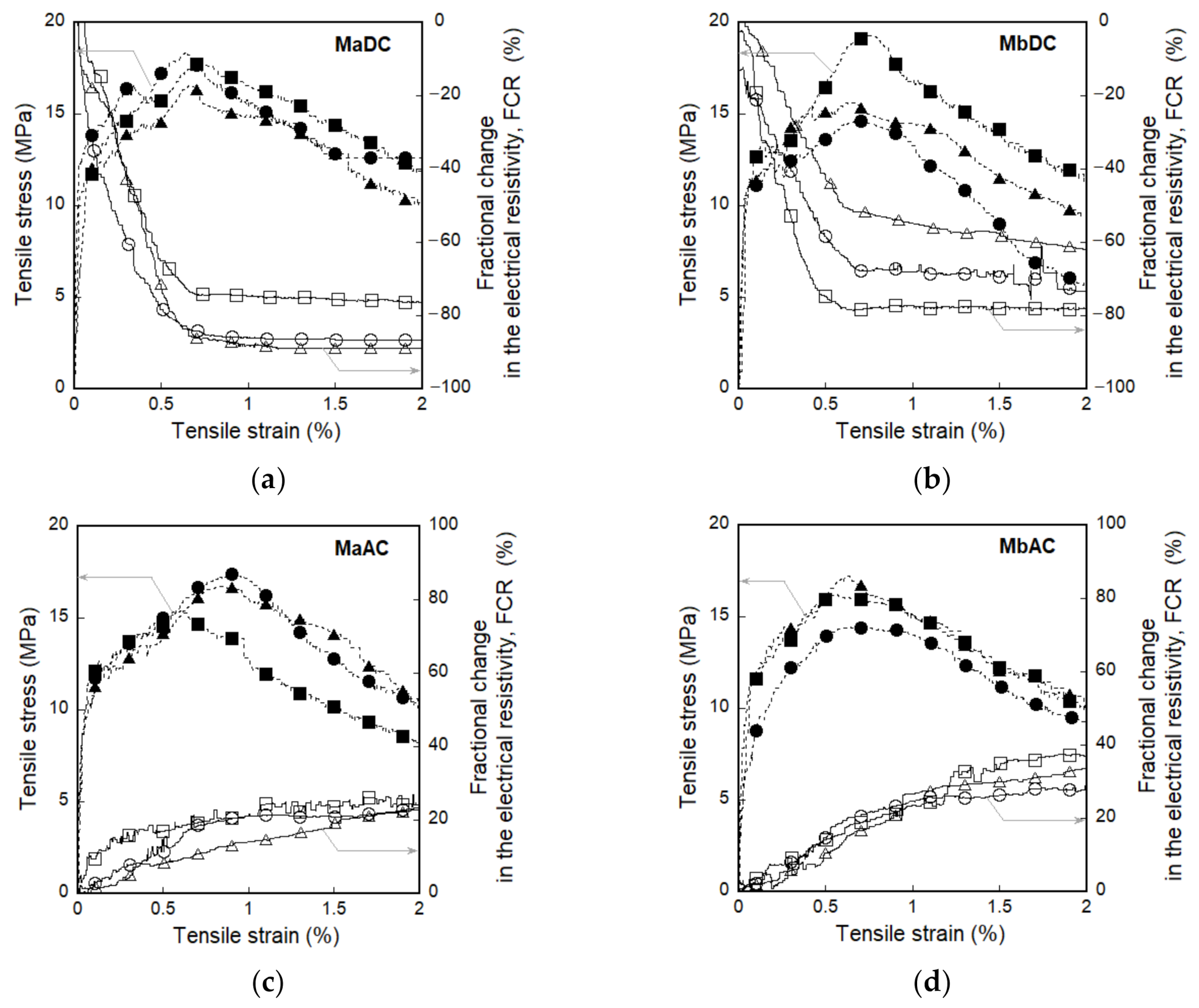
3.1. Electromechanical Response of Smart UHPCs under Direct Tension

The electromechanical responses of smart UHPCs under direct tension were clearly different depending on the electrical current source (DC or AC); however, all smart UHPCs exhibited strain-hardening behavior accompanied by multiple microcracks.
Figure 6 shows the electromechanical response of smart UHPCs under direct tension according to the different current sources. Figure 6a,b show the tensile stress (and fractional change in the electrical resistivity) versus strain of Ma and Mb measured using the DC multimeter (MaDC and MbDC), respectively, while Figure 6c,d display that of Ma and Mb measured using the AC multimeter (MaAC and MbAC), respectively. Table 3 summarizes the values of the mechanical parameters (εcc, εpc, σcc, σpc, and ncr) and electrical parameters (ρi, ρcc, ρpc, Δρcc, and Δρpc) of MaDC, MbDC, MaAC, and MbAC.
Regardless of applied current sources, as seen in Figure 7, the initial electrical resistivities of smart UHPCs are significantly dependent on the functional fillers. The initial electrical resistivities of Ma and Mb under direct tension (ρi) were 542.8 and 496.3 kΩ·cm for DC measurement (MaDC and MbDC) and 106.0 and 16.9 kΩ·cm for AC measurement (MaAC and MbAC), respectively. Thus, the electrical resistivities of smart UHPCs containing FSSAs (Mb series) were notably lower than those of Ma series. Moreover, it was noticeable that the electrical resistivities of smart UHPCs measured using a DC multimeter were always higher than those measured using an AC multimeter, regardless of functional fillers. To compare the real parts of electrical impedance measured using an AC multimeter with the resistance measured using a DC multimeter, the fixed frequencies were determined at the point where the imaginary part of the electrical impedance was closest to zero (0), i.e., Rcusp in the Nyquist plot. The real part of the electrical impedance cannot be equal to the resistance measured using a DC multimeter because the real part of the electrical impedance at Rcusp is not exactly zero.
The fractional change in the electrical resistivity (FCR) of a specimen under direct tension corresponding to the applied current sources are illustrated in Figure 8. The FCR (=(ρxρi)/ρi) is the rate of change in electrical resistivity due to factors such as strain, damage, or stress— ρx is the electrical resistivity corresponding to certain value of x coordinate such as strain, damage, stress or time. The fractional change in the electrical resistivity at both first-cracking and postcracking points (FCRcc and FCRpc) were calculated to evaluate the strain and damage self-sensing capacities using Equation (2).
F C R c c = ρ c c ρ i ρ i × 100 = Δ ρ c c ρ i × 100 F C R p c = ρ p c ρ c c ρ c c × 100 = Δ ρ p c ρ c c × 100
where, FCRcc is the FCR at the first-cracking point, FCRpc is the FCR from the first-cracking point to the postcracking point, ρcc is the electrical resistivity at the first-cracking point, ρpc is the electrical resistivity at the postcracking point, Δρcc is the change in the electrical resistivity until first-cracking point, and Δρpc is the change in the electrical resistivity from the first-cracking point to the postcracking point.
The FCR based on the DC measurement significantly decreased, as the tensile strain increased regardless of functional fillers, as shown in Figure 6a,b, whereas the FCR based on the AC measurement slightly increased as shown in Figure 6c,d. In addition, both FCRcc and FCRpc of smart UHPCs based on the DC measurement were significantly higher than those based on the AC measurement. As shown in Figure 8, the FCRpc of MaDC and MbDC (the DC measurement) values were 81.1% and 63.4%, respectively, while those of MaAC and MbAC (the AC measurement) were 17.0% and 16.9%, respectively.
The use of FSSAs did not generate a significant effect on the FCR values of smart UHPCs, as shown in Figure 8, although the electrical resistivities significantly decreased after adding FSSAs to smart UHPCs. Based on the results obtained using the DC multimeter, the maximum and minimum values of FCRcc were 4.9% and 1.2%, while those of FCRpc were 81.1% and 63.4% for MaDC and MbDC series, respectively. The FCRcc values of MaAC and MbAC were 2.0% and 1.4%, while the FCRpc values of MaAC and MbAC were 17.0% and 16.9%, respectively.

3.2. Electromechanical Responses of Smart UHPCs under Compression

Figure 9 shows the electromechanical responses of smart UHPCs under compression corresponding to different current sources. Figure 9a,b show the compressive stress (and FCR) versus time curves of MaDC and MbDC, while Figure 9c,d show those of MaAC and MbAC. Table 4 summarizes the peak stress (σp) and values of the electrical parameters (ρ0, ρp, and Δρp) of MaDC, MbDC, MaAC, and MbAC.
As shown in Table 4, the electrical resistivities of smart UHPCs specimens under compression were clearly dependent on the functional fillers, similar to those of the tensile specimens. The initial electrical resistivities (ρ0) of compressive specimens of MaDC and MbDC were 11352.3 and 10048.6 kΩ·cm, respectively, for DC measurement, while those of MaAC and MbAC were 2584.5 and 1465.6 kΩ·cm, respectively, for AC measurement. Moreover, the electrical resistivities of smart UHPCs measured using a DC multimeter for compressive specimens were always higher than those measured using AC multimeter.
The FCRs based on both DC and AC measurement significantly decreased as the compressive stress increased, as shown in Figure 9. To compare self-stress sensing capacities, FCRp values were calculated from the curves in Figure 9 using Equation (3).
F C R p = ρ p ρ 0 ρ 0 × 100 = Δ ρ p ρ 0 × 100
where, FCRp is the FCR at peak stress, ρp is the electrical resistivity at peak stress, and Δρp is the change in the electrical resistivity until peak stress.
The FCRp values of smart UHPCs based on the DC measurements were higher than those based on the AC measurements; the FCRp values based on the DC measurement was 47.91% and 47.50% for MaDC and MbDC, respectively, while those based on the AC measurement were 34.43% and 45.63% for MaAC and MbAC, respectively.
Figure 10 shows the effects of the FSSAs on the FCR values of smart UHPCs. The FCRp of smart UHPCs based on the DC measurement for Ma (series containing only steel fibers) was similar with Mb (series containing steel fibers and FSSAs), whereas that based on the AC measurement for Mb series was 24.55% higher than that for Ma series.

4. Discussion

4.1. Electromehcanical Response of Smart UHPCs under Direct Tension

Figure 6 shows the fractional change in the electrical resistivity (FCR) of smart UHPCs under direct tension corresponding to the functional fillers (only steel fibers, Ma; and steel fibers and fine steel slag aggregates, Mb).
The electromechanical responses of smart UHPCs containing steel fibers under direct tension has been reported mainly under DC measurement [2,3,4,6,7]. Le and Kim [21] reported that the reduction in electrical resistivity of SH-SFRCs occurred during fiber-matrix debonding after matrix cracking. Song et al. [2] and Nguyen et al. [3] attributed the reduction in the electrical resistance of SH-SFRCs to the formation of multiple micro-cracks during the strain-hardening region. They explained that the total electrical resistance of the SH-SFRCs could be classified into the electrical resistance of cracked and noncracked parts. The electrical resistance of the cracked part was much lower than that of the noncracked part because steel fibers bridging the microcrack at the cracked part were highly conductive. Thus, the total electrical resistance of SH-SFRC decreased as the number of microcracks increased [2,3,4,6,7].
As the tensile strain of smart UHPCs increased, their electrical resistances measured using a DC multimeter decreased regardless of functional fillers, as shown in Figure 6a,b. The change in the electrical resistivity (Δρcc and Δρpc) of MaDC (26.8 and 440.2 kΩ·cm) was higher than that of MbDC (6.2 and 318.47 kΩ·cm). Although the FSSAs were additionally added as functional fillers in the smart UHPCs containing steel fibers, the reason for higher change in the electrical resistivity of smart UHPCs containing only steel fibers is closely related to the fiber bridging under direct tension. The reduction in the electrical resistivity of smart UHPCs containing steel fibers is caused by the electrical current flowing through only the steel fibers connecting the matrix by fiber bridging at the cracked part [2,3,4,6,7]. The change in the electrical resistivity of smart UHPCs containing only steel fibers depends only on the steel fibers, while that containing steel fibers and FSSAs is affected by both steel fibers and FSSAs. The FSSAs in smart UHPCs induces an increase of conductive network between the functional fillers and between the matrix and functional filler, thus the initial electrical resistivity (ρi) of smart UHPCs decreases: the ρi of Ma (containing only steel fibers) measured using a DC multimeter was 542.8 kΩ·cm, while that of Mb was 496.3 kΩ·cm.
The distance between conductive functional fillers (steel fibers and FSSAs) directly influenced on the tunneling effect [14,15,26], while the number of fibers (Nf) in Equation (4) and the number of contacting fibers (Ncf) in Equation (5), proposed by Xu et al. [27], directly affected the connected electrically conductive networks in smart UHPCs. In this study, both Ma and Mb contained 2 vol.% steel fibers (connected networks between steel fibers was same), the difference in the electrical resistivity between Ma and Mb was dependent upon the distance between functional fillers (FSSAs). The distance between FSSAs (Lpf) was calculated by using the following Equation (6), proposed by Xiao et al. [28], based on the assumption that the fillers are uniformly distributed.
N f = V o V c V f = V o V c π d f 2 l f 4
N c f = 8 V c V o c o s 1 13.8 × d f l f 1 V o ( π d f ) 2 × l f
L p f = d p f × π 6 1 3 × V p f 1 3 1
where, Vo and Vpf are the volume content of steel fibers and FSSAs, respectively; Vc and Vf are the volume of composites and a steel fiber, respectively; lf and df are the length and diameter of steel fiber; and dpf is the diameter of FSSA.
The distribution of functional fillers (steel fibers and FSSAs) in smart UHPCs was observed by using a stereoscopic microscope (Huvits Lusis HC-30MU camera), as shown in Figure 11. Figure 11a,b shows the distribution of fillers in the Ma series containing only steel fibers and that of the Mb series containing steel fibers and FSSAs, respectively. Both steel fibers and FSSAs were uniformly distributed in smart UHPCs, as shown in Figure 11. Moreover, conductive networks of steel fibers and FSSAs were well formed as shown in Figure 11a,b. The Nf, Ncf, and Lpf are summarized in Table 5. The Nf and Ncf of the specimens for tensile tests were calculated as 1179 and 1106 because the length and diameter of steel fibers were 30 and 0.3 mm, respectively. The Lpf in Mb series was calculated as 220.1 μm. Thus, the distance between functional fillers including FSSAs and steel fibers would be lower in the Mb than the Ma series because of the addition of FSSAs in the Mb series.
However, when smart UHPCs under direct tension generated multiple microcracks during tensile stain hardening region, it was questioned whether the electrical resistances of smart UHPCs were mainly affected by the reduced electrical resistance at each cracked part of multiple cracks [2,3,4,6,7] or by the increased distance between functional fillers.

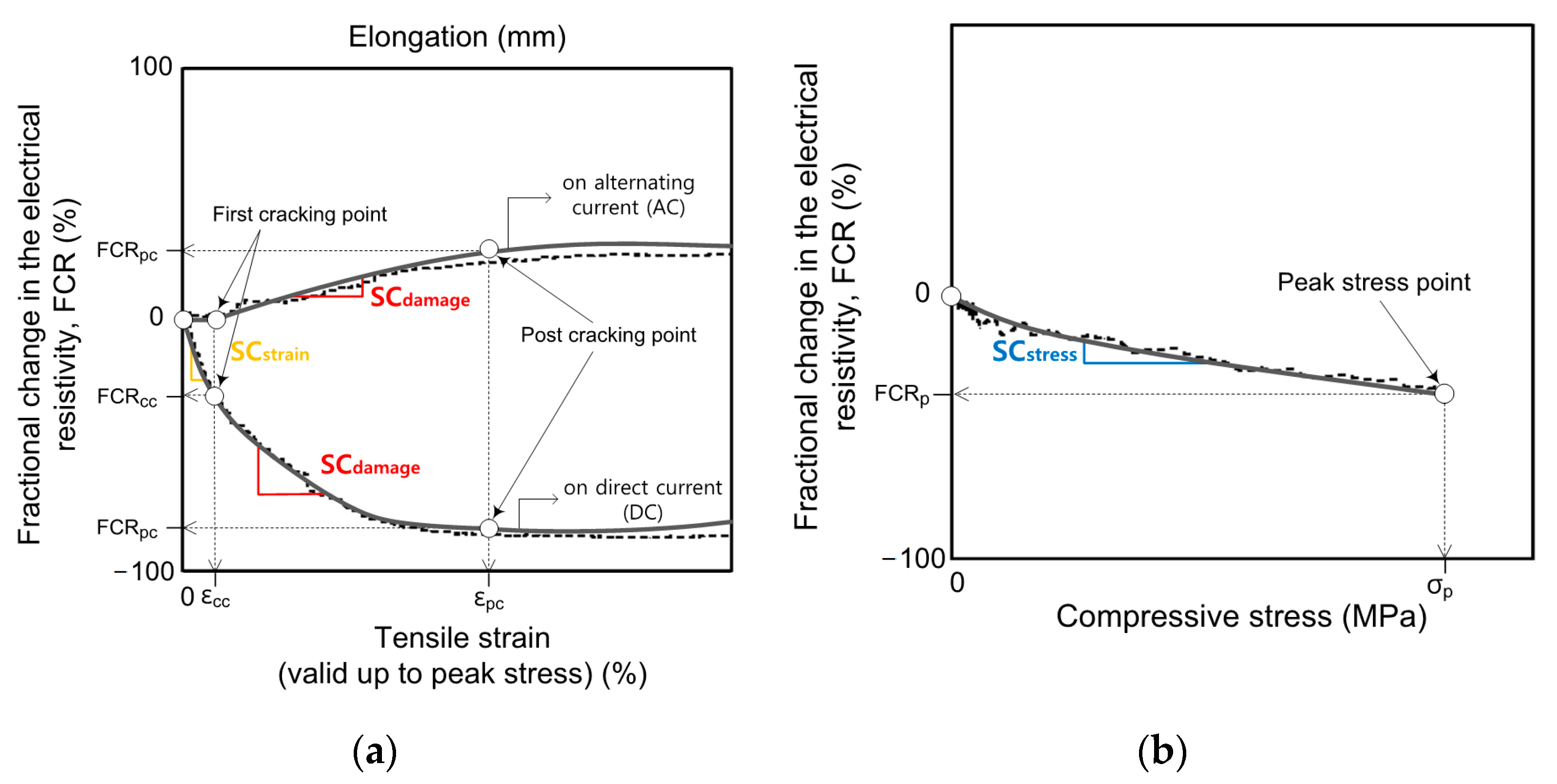
4.2. The Self-Sensing Capacity of Smart UHPCs under External Loads Corresponsding to the Different Current Sources

Sensitivity is an important factor evaluating the sensing property of smart UHPCs, and can be characterized by sensitivity coefficient [1]. Although most of the studies evaluated the self-strain- and -damage-sensing capacity of SCMs under direct tension or compression by using gage factors [5,8,29], the stress-sensing capacity of SCMs evaluated by the stress sensitivity coefficient has been more frequently used instead of the gage factor [8,29]. Furthermore, the strain or damage gage factor is also known as strain or damage sensitivity coefficient [1]. Therefore, in this study, sensitivity coefficient was used to compare and analyze strain-, damage-, and stress-sensing capacity. To quantify the self-strain, -damage, and -stress sensing capacity of smart UHPCs, the sensitivity coefficients were calculated using the following Equation (7):
S C s t r a i n = G F s t r a i n = F C R c c ε c c S C d a m a g e = G F d a m a g e = F C R p c ε p c ε c c S C s t r e s s = F C R p σ p
where, SCstrain, SCdamage, and SCstress are the strain, damage, and stress sensitivity coefficients, respectively, GFstrain and GFdamage are the strain and stress gage factors, respectively.
Figure 12 shows the typical tensile strain (ε) or compressive stress (σ) until peak stress and FCR of smart UHPCs. Strain and damage sensitivity coefficients (SCstrain and SCdamage) are the ratio between fractional change in the electrical resistivity (FCR) and mechanical strain (ε), while a stress sensitivity coefficient (SCstress) is the ratio of FCR to the mechanical stress (σ). SCstrain represents the self-strain sensing capacity of smart UHPCs under direct tension within the elastic range prior to the first cracking, whereas SCdamage represents the self-damage sensing capacity of smart UHPCs under direct tension from first cracking to the post cracking point. Moreover, SCstress represents the self-stress-sensing capacity of smart UHPCs under compression.
For the smart UHPCs under direct tension, both SCstrain and SCdamage of MaDC were significantly higher than those of MbDC; the SCstrain values of MaDC and MbDC were 188.9% and 42.6%/%, respectively, while the SCdamage values were 128.7% and 96.1%/%, respectively. The SCstrain (67.9%/%) of Ma based on the AC measurement was also higher than that of Mb (46.8%/%), whereas SCdamage of Ma (25.7%/%) and Mb (29.1%/%) values based on the AC measurement were similar. Based on the sensitivity coefficients, both strain and damage self-sensing capacities of Ma (with only steel fibers) were superior to Mb (with both steel fibers and FSSAs). Therefore, DC measurement was more suitable for self-strain- and self-damage-sensing capacities of smart UHPCs than AC measurement.
In comparison with previous research, the GFstrain (188.9%/%) of MaDC in this study was significantly higher than that of SCM containing carbon fiber (59%/%) [30]. The GFdamage of MaDC (129%/%) was significantly higher than that (28.3%/%) of smart UHPCs used by Kim et al. [6], whereas the GFstrain (188.9%/%) of MaDC was lower than that (433%/%) of smart UHPCs used by Kim et al. [6]. On the other hand, from the AC measurement, the GFstrain (67.97%/%) of MaAC was lower than that (247%/%) of SCMs containing carbon blacks but higher than that (24%/%) of the SCMs containing PVA fibers.
Although the FCRp values of MaDC and MbDC were similar, the SCstress (0.33%/MPa) of MaDC was higher than that (0.28%/MPa) of MbDC. However, the SCstress of MbAC (0.27%/MPa) was slightly higher than that of MaAC (0.25%/MPa), although the FCRp of MbAC (45.63%) was much higher than that of MaAC (34.43%). Thus, the effect of adding FSSAs on the self-stress-sensing capacities of smart UHPCs was greater under DC measurement than under AC measurement.
Regarding the SCstress, MaDC produced the highest SCstress (0.33%/MPa) from the DC measurement while MbAC did the highest one (0.27%/MPa) from the AC measurement. The (0.28%/MPa) of SCMs containing carbon black from DC measurement, reported by Monteiro et al. [29], was slightly lower than that (0.33%/MPa) of MaDC, while the SCstress (0.41%/MPa) of the smart UHPCs containing only 1.0% FSSAs from AC measurement [8] was higher than that (0.27%/MPa) of MbAC.

4.3. Effects of Different Current Sources (DC or AC) on the Electromechanical Response of Smart UHPCs under External Loads

As the tensile strain of smart UHPCs increased, their electrical resistances measured from DC multimeter decreased regardless of functional fillers, as shown in Figure 6a,b. However, the electrical resistances of smart UHPCs measured using AC multimeter increased as their tensile strain increased, as shown in Figure 6c,d. The self-sensing mechanisms of smart UHPCs based on the AC measurement commonly include tunneling effects and conductive networks. In other words, the change in the electrical resistance (or response) of smart UHPCs under AC measurement was primarily due to the tunneling effects between two conductive particles and electrically connected (conductive) networks, including continuously connected pores and connected steel or carbon fibers [11,13]. However, under DC measurements, such changes were mostly dependent on the fiber crack bridging effects at cracked parts, as explained before. Thus, the electrical resistances of smart UHPCs under direct tension, when they were measured from AC multimeter, increased because of longer distance between conductive functional fillers (FSSAs) and the stretched conductive network of steel fibers in the composites.
The basis of different self-sensing mechanisms corresponding to different electrical current source would be the different relationships between charge mobility and tunneling effect. Figure 13 illustrates the movement of electrons under DC or AC current. Electrons move from the negative to the positive pole under DC measurement, whereas under AC measurement electrons remain static and vibrate in their current positions [31]. The tunneling effect refers to a phenomenon in which electrons pass through an electromagnetic barrier because the kinetic energy of the electrons is greater than that of the electromagnetic barrier [32]. Thus, the tunneling effect under AC measurement would be higher than that under DC measurement. Moreover, difference in electrical current penetration, according to DC and AC measurements, would also generate the different electrical resistance. The magnetic field created by DC generally penetrates the entire cross-section of the object, whereas that created by AC is concentrated in a thin layer on the object, that called “skin effect” [33]. Consequently, the initial electrical resistivity of specimens measured from AC multimeter was significantly lower than that of specimens measured from DC multimeter. Furthermore, penetration depth is also affected by the frequency—as the frequency increases, the penetration depth decreases [34]. The fixed frequency, in this study, for tensile specimen was 500 Hz, whereas that for compressive specimen was 100 Hz. Thus, the penetration depth in tensile specimens with high frequency was smaller than that in compressive specimens with low frequency. Consequently, the initial electrical resistivity of a compressive specimen with high penetration depth was higher than that of a tensile specimen. The electrical resistance of smart UHPCs under DC measurement would primarily depend on fiber crack bridging, while that under AC measurement would primarily depend on the tunneling effect. Hence, as the tensile strain increased with an increasing number of multiple micro cracks, the electrical resistance of smart UHPCs under DC measurement decreased, owing to fiber crack-bridging effects, whereas that under AC measurement increased owing to tunneling effects.
In addition, self-strain-sensing capacity of smart UHPCs until σcc (first-cracking strength point) was notably different corresponding to the applied electrical current source. As shown in Figure 14, the electrical resistivity of smart UHPCs under DC measurement slightly changed prior to the first cracking strength point, but it significantly decreased after that point. Even though the tensile strain of smart UHPCs increased gradually prior to the first cracking strength point, the electrical resistance of smart UHPCs changed slightly prior to first cracking. This was because the electrical current mostly flowed through the mortar matrix under DC measurement, which mainly depends on fiber crack bridging. However, after first cracking, the electrical current started to flow through the highly conductive steel fibers at the cracked section. Therefore, the electrical resistances of smart UHPCs started to decrease noticeably from the first cracking point to post cracking point. On the other hand, the electrical resistances of smart UHPCs changed slightly under AC measurement because the electromechanical responses of smart UHPCs measured using the AC multimeter were primarily dependent on the tunneling effect. The tunneling effect was nearly constant prior to the first cracking point, as the tensile strain was very small. Thus, DC measurements would be more suitable than AC measurements for the tensile self-strain sensing of smart UHPCs.
In general, the changes in the electrical resistivities increased linearly as the applied compressive stress increased, as shown in Figure 15. The linear relationship would be utilized to measure the amount of applied compressive stress based on the measured electrical resistivity. Moreover, the electrical resistivities of smart UHPCs under compression decreased as the compressive stress increased, regardless of the applied electrical current sources, because the electromechanical responses of smart UHPCs under compression were only dependent on the tunneling effect.

5. Conclusions

This study investigated the electromechanical responses of smart UHPCs corresponding to the different current sources (DC or AC) to clarify self-strain-, -damage-, and -stress-sensing mechanisms, and consequently to suggest a suitable measurement method of electrical response according to the self-sensing purpose.
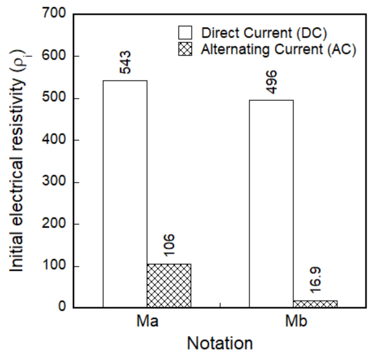
  • The self-sensing mechanism from DC measurement would be mainly dependent on fiber crack bridging, whereas that from AC measurement was primarily dependent on the tunneling effect.
  • The electrical resistivities, from both DC and AC measurements, of smart UHPCs under compression clearly decreased as the applied stress increased, regardless of the types of aggregates, because the electrical responses of smart UHPCs under compression were primarily dependent upon the tunneling effect.
  • Regarding the stress self-sensing capacities of smart UHPCs under compression, the self-sensing capacities of smart UHPCs from DC measurement were moderately higher than that from AC measurement: the SCstress of MaDC and MaAC were 0.33% and 0.25%/MPa, respectively, while those of MbDC and MbAC were 0.28% and 0.27%/MPa, respectively.
  • Under tension, as the tensile strain and the number of multiple microcracks of smart UHPCs increased, the electrical resistances from DC measurement significantly decreased, whereas those from AC measurement slightly increased owing, to different self-sensing mechanism.
  • Regarding the self-strain- and -damage-sensing capacities of smart UHPCs under tension, the self-sensing capacities of smart UHPCs from DC measurement were significantly higher those from AC measurement: the SCstrain values of MaDC and MaAC were 188.9% and 67.9%/%, respectively, while SCdamage values of MaDC and MaAC were 128.7% and 25.7%/%, respectively.
In future research, we intend to investigate the effects of different (embedded or attached) electrodes on the electromechanical responses of smart UHPCs corresponding to different loading conditions. Moreover, it is necessary to further investigate the electromechanical response of smart UHPCs containing different aggregates as functional fillers.

Author Contributions

Investigation and writing—original draft preparation, M.K.K.; writing—review, H.V.L. and D.J.K.; conceptualization, D.J.K. All the authors have read and agreed to the published version of the manuscript.

Funding

This research was supported by a grant (21CTAP-C157281-02) from Technology Advancement Research Program funded by Ministry of Land, Infrastructure, and Transport of Korean government.

Institutional Review Board Statement

Not applicable.

Informed Consent Statement

Not applicable.

Data Availability Statement

Not applicable.

Acknowledgments

This research was supported by a grant (20CTAP-C157281-01) from Technology Advancement Research Program funded by Ministry of Land, Infrastructure, and Transport of Korean government.

Conflicts of Interest

The authors declare no conflict of interest.

References

  1. Han, B.; Yu, X.; Ou, J. Self-Sensing Concrete in Smart Structures; Butterworth-Heinemann, Elsevier: Kidlington, UK, 2014. [Google Scholar] [CrossRef]
  2. Song, J.; Nguyen, D.L.; Manathamsombat, C.; Kim, D.J. Effect of fiber volume content on electromechanical behavior of cementitious composites. J. Compos. Mater. 2015, 49, 3621–3634. [Google Scholar] [CrossRef]
  3. Nguyen, D.L.; Song, J.; Manathamsombat, C.; Kim, D.J. Comparative electromechanical damage-sensing behaviors of six strain-hardening steel fiber-reinforced cementitious composites under direct tension. Compos. B Eng. 2015, 69, 159–168. [Google Scholar] [CrossRef]
  4. Kim, M.K.; Kim, D.J.; An, Y.K. Electro-mechanical self-sensing response of ultra-high-performance fiber-reinforced concrete in tension. Compos. B Eng. 2018, 134, 254–264. [Google Scholar] [CrossRef]
  5. Ranade, R.; Zhang, J.; Lynch, J.P.; Li, V.C. Influence of micro-cracking on the composite resistivity of Engineered Cementitious Composites. Cem. Concr. Res. 2014, 58, 1–12. [Google Scholar] [CrossRef]
  6. Kim, M.K.; Kim, D.J. Electromechanical response of high-performance fiber-reinforced cementitious composites containing milled glass fibers under tension. Materials 2018, 11, 1115. [Google Scholar] [CrossRef] [Green Version]
  7. Kim, M.K.; Kim, D.J. Effects of Milled Glass Fibers on the Damage-sensing Capacity of Steel-fiber-reinforced Cementitious Composites. J. Korea Concr. Inst. 2017, 29, 457–464. [Google Scholar] [CrossRef]
  8. Lee, Y.S.; Le, H.V.; Kim, D.J. Self-stress sensing smart concrete containing fine steel slag aggregates and steel fibers under high compressive stress. Constr. Build. Mater. 2019, 220, 149–160. [Google Scholar] [CrossRef]
  9. Li, X.; Li, M. Multifunctional self-sensing and ductile cementitious materials. Cem. Concr. Res. 2019, 123, 105714. [Google Scholar] [CrossRef]
  10. Hou, T.C.; Lynch, J.P. Conductivity-based strain monitoring and damage characterization of fiber reinforced cementitious structural components. In Proceedings of the SPIE Smart Structures and Materials + Nondestructive Evaluation and Health Monitoring, San Diego, CA, USA, 17 May 2005; pp. 419–429. [Google Scholar] [CrossRef]
  11. Nguyen, D.L.; Kim, D.J.; Thai, D.K. Enhancing damage-sensing capacity of strain-hardening macro-steel fiber-reinforced concrete by adding low amount of discrete carbons. Materials 2019, 12, 938. [Google Scholar] [CrossRef] [PubMed] [Green Version]
  12. Le, H.V.; Lee, D.H.; Kim, D.J. Effects of steel slag aggregate size and content on piezoresistive responses of smart ultra-high-performance fiber-reinforced concretes. Sens. Actuators A 2020, 305, 111925. [Google Scholar] [CrossRef]
  13. Yoo, D.Y.; Kim, S.; Lee, S.H. Self-sensing capability of ultra-high-performance concrete containing steel fibers and carbon nanotubes under tension. Sens. Actuators A 2018, 276, 125–136. [Google Scholar] [CrossRef]
  14. Han, B.G.; Han, B.Z.; Yu, X. Experimental study on the contribution of the quantum tunneling effect to the improvement of the conductivity and piezoresistivity of a nickel powder-filled cement-based composite. Smart Mater. Struct. 2009, 18, 1–7. [Google Scholar] [CrossRef]
  15. Li, H.; Xiao, H.G.; Ou, J.P. Effect of compressive strain on electrical resistivity of carbon black-filled cement-based composites. Cem. Concr. Compos. 2006, 28, 824–828. [Google Scholar] [CrossRef]
  16. Wen, S.; Chung, D.D.L. Self-sensing of flexural damage and strain in carbon fiber reinforced cement and effect of embedded steel reinforcing bars. Carbon 2006, 44, 1496–1502. [Google Scholar] [CrossRef]
  17. Xu, J.; Cao, Y.; Jiang, L.; Feng, W.; Song, Y.; Shan, H. Microstructure and pressure-sensitive properties of cement-based composite with Ni nanowires. Constr. Build. Mater. 2018, 159, 46–53. [Google Scholar] [CrossRef]
  18. Wen, S.; Chung, D.D.L. Uniaxial compression in carbon fiber-reinforced cement, sensed by electrical resistivity measurement in longitudinal and transverse directions. Cem. Concr. Res. 2001, 31, 297–301. [Google Scholar] [CrossRef]
  19. Kim, M.K.; Park, J.; Kim, D.J. Characterizing the electro-mechanical response of self-sensing steel-fiber-reinforced cementitious composites. Constr. Build. Mater. 2020, 240, 117954. [Google Scholar] [CrossRef]
  20. Le, H.V.; Kim, D.J. Effects of Matrix Strength, Fiber Type, and Fiber Content on the Electrical Resistivity of Steel-Fiber-Reinforced Cement Composites during Fiber Pullout. J. Korean Soc. Civ. Eng. 2019, 39, 675–689. [Google Scholar]
  21. Le, H.V.; Kim, D.J. Effect of matrix cracking on electrical resistivity of high performance fiber reinforced cementitious composites in tension. Constr. Build. Mater. 2017, 156, 750–760. [Google Scholar] [CrossRef]
  22. Noh, H.W.; Kim, M.K.; Kim, D.J. Comparative Performance of Four Electrodes for Measuring the Electromechanical Response of Self-Damage Detecting Concrete under Tensile Load. Sensors 2019, 19, 3645. [Google Scholar] [CrossRef] [Green Version]
  23. Reza, F.; Baston, G.B.; Yamamuro, J.A.; Lee, J.S. Resistance changes during compression of carbon fiber cement composites. J. Mater. Civ. Eng. ASCE 2003, 50, 476–483. [Google Scholar] [CrossRef] [Green Version]
  24. Reza, F.; Batson, G.B.; Yamamuro, J.A.; Lee, J.S. Volume electrical resistivity of carbon fiber cement composites. ACI Mater. J. 2001, 98, 25–35. [Google Scholar] [CrossRef]
  25. Peled, A.; Torrents, J.M.; Mason, T.O.; Shah, S.P.; Garboczi, E.J. Electrical impedance spectra to monitor damage during tensile loading of cement composites. ACI Mater. J. 2001, 98, 313–322. [Google Scholar] [CrossRef]
  26. Fan, S.; Li, X.; Li, M. The effects of damage and self-healing on impedance spectroscopy of strain-hardening cementitious materials. Cem. Concr. Res. 2018, 106, 77–90. [Google Scholar] [CrossRef]
  27. Xu, J.; Zhong, W.; Yao, W. Modeling of conductivity in carbon fiber-reinforced cement-based composites. J. Mater. Sci. 2010, 3538–3546. [Google Scholar] [CrossRef]
  28. Xiao, H.; Li, H.; Ou, J. Modeling of piezoresistivity of carbon black filled cement-based composites under multi-axial strain. Sens. Actuator A Phys. 2012, 160, 87–93. [Google Scholar] [CrossRef]
  29. Monteiro, A.O.; Cachim, P.B.; Costa, P.M.F.J. Self-sensing piezoresistive cement composite loaded with carbon black particles. Cem. Concr. Compos. 2017, 81, 59–65. [Google Scholar] [CrossRef]
  30. Wen, S.; Chung, D.D.L. Uniaxial tension in carbon fiber reinforced cement, sensed by electrical resistivity measurement in longitudinal and transverse directions. Cem. Concr. Res. 2000, 30, 1289–1294. [Google Scholar] [CrossRef]
  31. Lowe, D. Chapter 2: Understanding Electricity (Comparing Direct and Alternating Current). In Electronics All-in-One for Dummies; Book 1: Getting Started in Electronics; John Wiley & Sons, Inc.: New York, NY, USA, 2012; pp. 34–35. [Google Scholar]
  32. Davies, P.C.W. Quantum tunneling time. Am. J. Phys. 2005, 73. [Google Scholar] [CrossRef] [Green Version]
  33. Mutrhy, C.R.L. 5.2.1 Magnetic field using an electric current. In Non-destructive Test and Evaluation of Materials; McGraw Hill: New York, NY, USA, 2008; p. 126. [Google Scholar]
  34. He, D.F.; Yoshizawa, M.; Oyama, Y.; Nakamura, M. Detecting defect in cast iron using high-TC SQUID. Physica C Superconduct. 2004, 412, 1480–1483. [Google Scholar] [CrossRef]
Figure 1. Experimental program.
Sensors 21 01281 g001
Figure 2. Geometry of functional fillers: (a) long smooth steel fibers, (b) short smooth steel fiber, (c) fine steel slag aggregates.
Sensors 21 01281 g002
Figure 3. Test set-up: (a) direct tensile test under direct current (DC) or alternating current (AC) measurement, (b) compressive test under direct current (DC) or alternating current (AC) measurements.
Sensors 21 01281 g003
Figure 4. Impedance spectroscopy response of smart ultra-high-performance concretes (smart UHPCs) on alternating current (AC) without load: (a) tensile specimens, (b) compressive specimens.
Sensors 21 01281 g004
Figure 5. Typical electrical polarization response under direct current measurement without load: (a) Ma, (b) Mb.
Sensors 21 01281 g005
Figure 6. Electromechanical response of smart UHPCs corresponding to the different current sources under direct tension: (a) MaDC, (b) MbDC, (c) MaAC, (d) MbAC.
Sensors 21 01281 g006
Figure 7. Initial electrical resistivity corresponding to the functional fillers.
Sensors 21 01281 g007
Figure 8. Fractional change in the electrical resistivities (FCR) of smart UHPCs with different current sources and aggregates under direct tension.
Sensors 21 01281 g008
Figure 9. Fractional change in the electrical resistivity (FCR) of smart UHPCs corresponding to the different current sources under compression: (a) MaDC, (b) MbDC, (c) MaAC, (d) MbAC.
Sensors 21 01281 g009
Figure 10. Fractional change in the electrical resistivity (FCR) of smart UHPCs with different current sources and aggregates under compression.
Sensors 21 01281 g010
Figure 11. The distribution and conductive network of functional fillers within smart UHPCs: (a) Ma series, (b) Mb series.
Sensors 21 01281 g011
Figure 12. Typical tensile strain or compressive stress until peak stress versus FCR and strain-, damage-, and stress-sensing coefficients of smart UHPCs: (a) under direct tension, (b) under compression.
Sensors 21 01281 g012
Figure 13. Theory of movement of electrons based on the tunneling effects [31,32]: (a) under direct current, (b) under alternating current.
Sensors 21 01281 g013
Figure 14. Electrical resistivity responses until first cracking point of smart UHPCs corresponding to the different current sources under direct tension: (a) MaDC, (b) MbDC, (c) MaAC, (d) MbAC.
Sensors 21 01281 g014
Figure 15. Electrical resistivity responses of smart UHPCs under compression: (a) MaDC, (b) MbDC, (c) MaAC, (d) MbAC.
Sensors 21 01281 g015
Table 1. Composition of matrix by weight ratio.
NotationCement
(Type 1)
Silica SandFine Steel Slag AggregateSilica FumeSilica PowderWaterSuper-Plasticizer *f′ck
(MPa)
Ma1.01.00-0.150.250.200.042178
Mb1.00.500.500.150.250.200.042179
* Superplasticizer contained 30% solid content.
Table 2. Properties of functional fillers.
TypeDiameter
(μm)
Length
(mm)
Density
(g/cm3)
Tensile Stregnth
(MPa)
Elastic Modulus
(GPa)
Long smooth steel fibers300307.92447200
Short smooth steel fibers20067.92104200
Fine steel slag aggregate<390----
Table 3. Electro-tensile parameters of smart UHPCs.
NotationSpe.Strain
(%)
Stress
(MPa)
CrackElectrical Resistivity
(kΩ·cm)
Change in the Electrical
Resistivity (kΩ·cm)
εccεpcσccσpcncrρiρccρpcΔρccΔρpc
Ma
DC
SP10.0240.6312.0918.3523.4588.8550.9100.937.9487.9
SP20.0450.708.0017.7222.1534.3530.2131.84.1402.5
SP30.0270.6610.3816.5620.4505.3466.975.238.4430.1
Aver.0.0320.6610.1617.5422.0542.8516.0102.626.8440.2
STD0.0090.031.680.741.234.635.723.116.135.6
Mb
DC
SP10.0290.689.3714.6419.2503.1492.0188.311.1314.8
SP20.0300.748.7619.2819.7515.0512.8116.72.2398.3
SP30.0290.654.3415.6318.6470.9465.8227.55.1243.4
Aver.0.0290.697.4916.5219.2496.3490.2177.56.2318.47
STD0.0000.042.242.000.418.619.245.93.763.3
Ma
AC
SP10.0240.6310.5519.2827.1110.8111.1133.5−0.3−22.4
SP20.0290.6610.5516.5425.7100.4104.5118.6−4.1−14.1
SP30.0290.898.7317.3923.3106.9108.5120.2−1.6−11.7
Aver.0.0270.739.9417.7425.4106.0108.0124.1−2.0−16.1
STD0.0020.120.861.151.64.32.76.71.64.6
Mb
AC
SP10.0300.605.7117.2219.519.019.322.8−0.3−3.5
SP20.0290.598.4618.4019.117.617.820.3−0.2−2.5
SP30.0290.656.0717.3618.914.214.416.4−0.2−2.0
Aver.0.0290.616.7517.6619.216.917.219.8−0.2−2.7
STD0.0000.031.220.530.22.02.02.60.00.6
ncr: number of microcracks; STD: standard derivation.
Table 4. Electro-compressive parameters of smart UHPCs.
NotationSpe. No.Peak Stress (MPa)Initial Electrical Resistivity
(kΩ·cm)
Electrical Resistivity at Peak Stress
(kΩ·cm)
Change in the Electrical Resistivity (kΩ·cm)
σpρ0ρpΔρp
Ma
DC
SP1147.9711544.96902.54642.4
SP2145.1510992.65957.35035.3
SP3142.0911519.54872.46647.1
Aver.145.0711352.35910.75441.6
STD2.40254.6829.4867.4
Mb
DC
SP1173.5211069.96323.24746.7
SP2171.169478.34759.44718.9
SP3171.169597.44814.94782.5
Aver.171.9510048.65299.24749.4
STD1.11723.9724.526.0
Ma
AC
SP1134.082430.51620.6809.9
SP2146.562878.21866.21012.0
SP3139.972444.91593.9851.0
Aver.140.202584.51693.6891.0
STD5.10207.8122.687.2
Mb
AC
SP1155.151481.5847.2634.3
SP2176.821482.1685.6796.5
SP3170.221433.1855.2577.9
Aver.167.401465.6796.0669.6
STD9.0723.078.192.7
Table 5. The number of fibers (Nf), the number of contacting fibers (Ncf), and distance between fine steel slag aggregates (Lpf) of the smart UHPCs under tension.
Loading
Condition
Matrix
Notation
The Number of Steel Fibers,
Nf
The Number of Initial Contacting Steel Fibers,
Ncf
Initial Distance between FSSAs,
Lpf (μm)
TensionMa11791106-
Mb11791106220.1
Publisher’s Note: MDPI stays neutral with regard to jurisdictional claims in published maps and institutional affiliations.

