
Miniature Coil for Wireless Power and Data Transfer through Aluminum †

Abstract
:1. Introduction
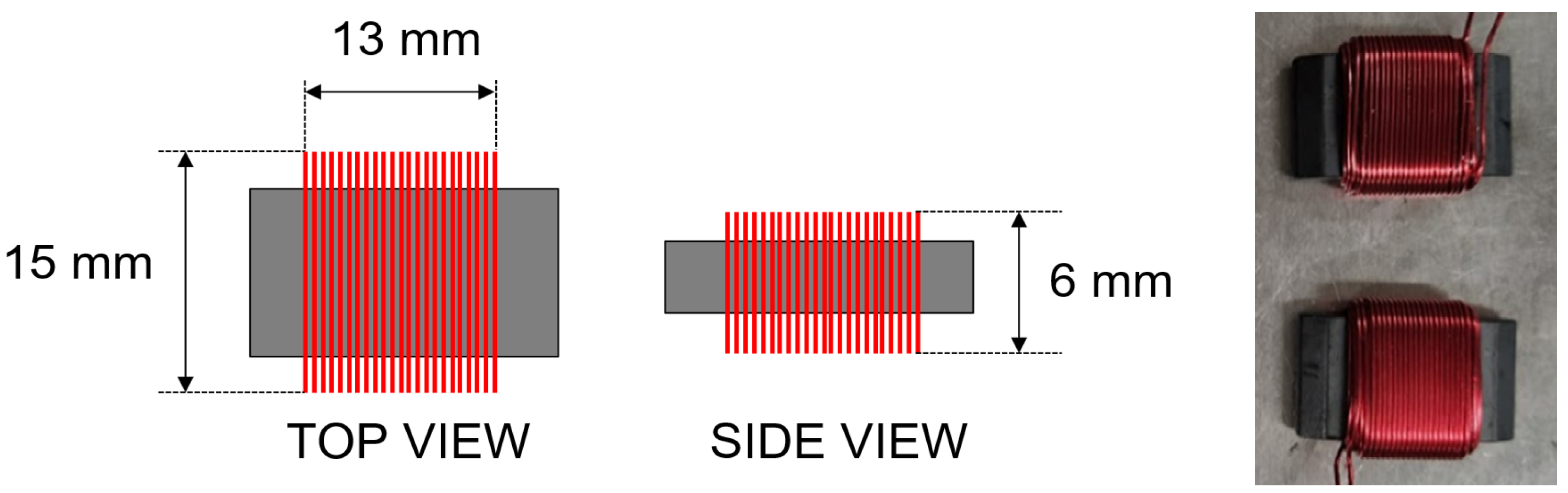
2. Miniature Coil
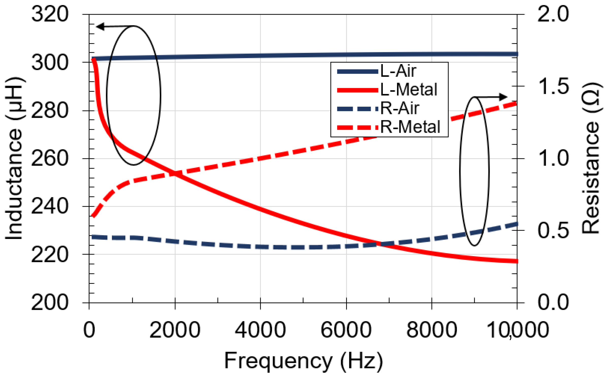
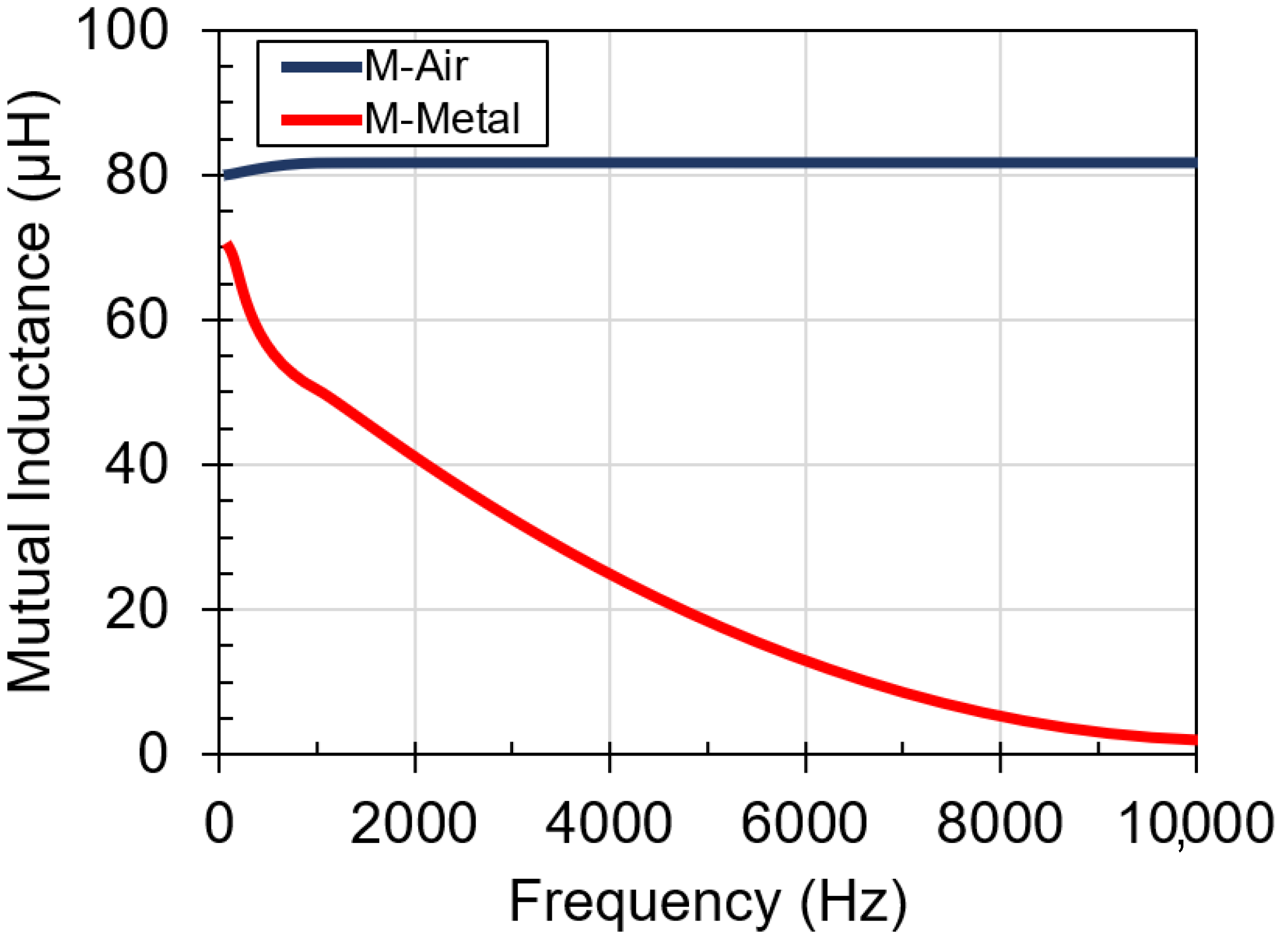
2.1. Metal Barrier Effect
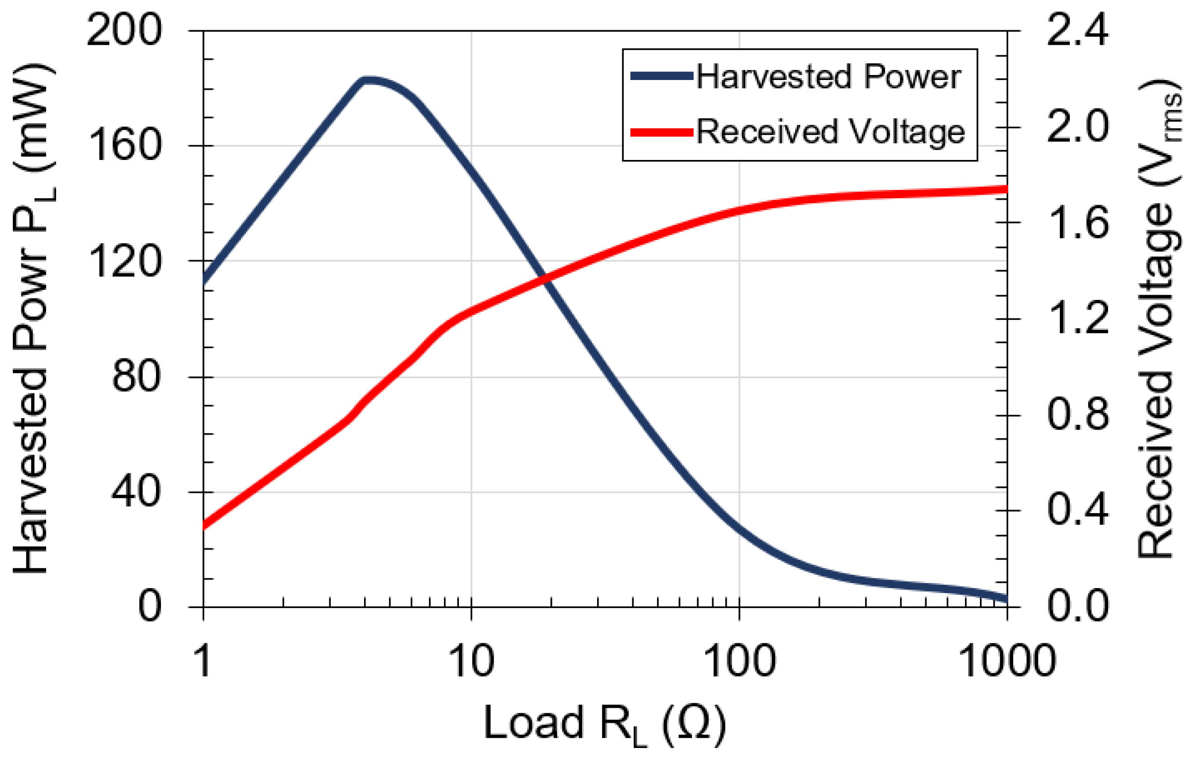
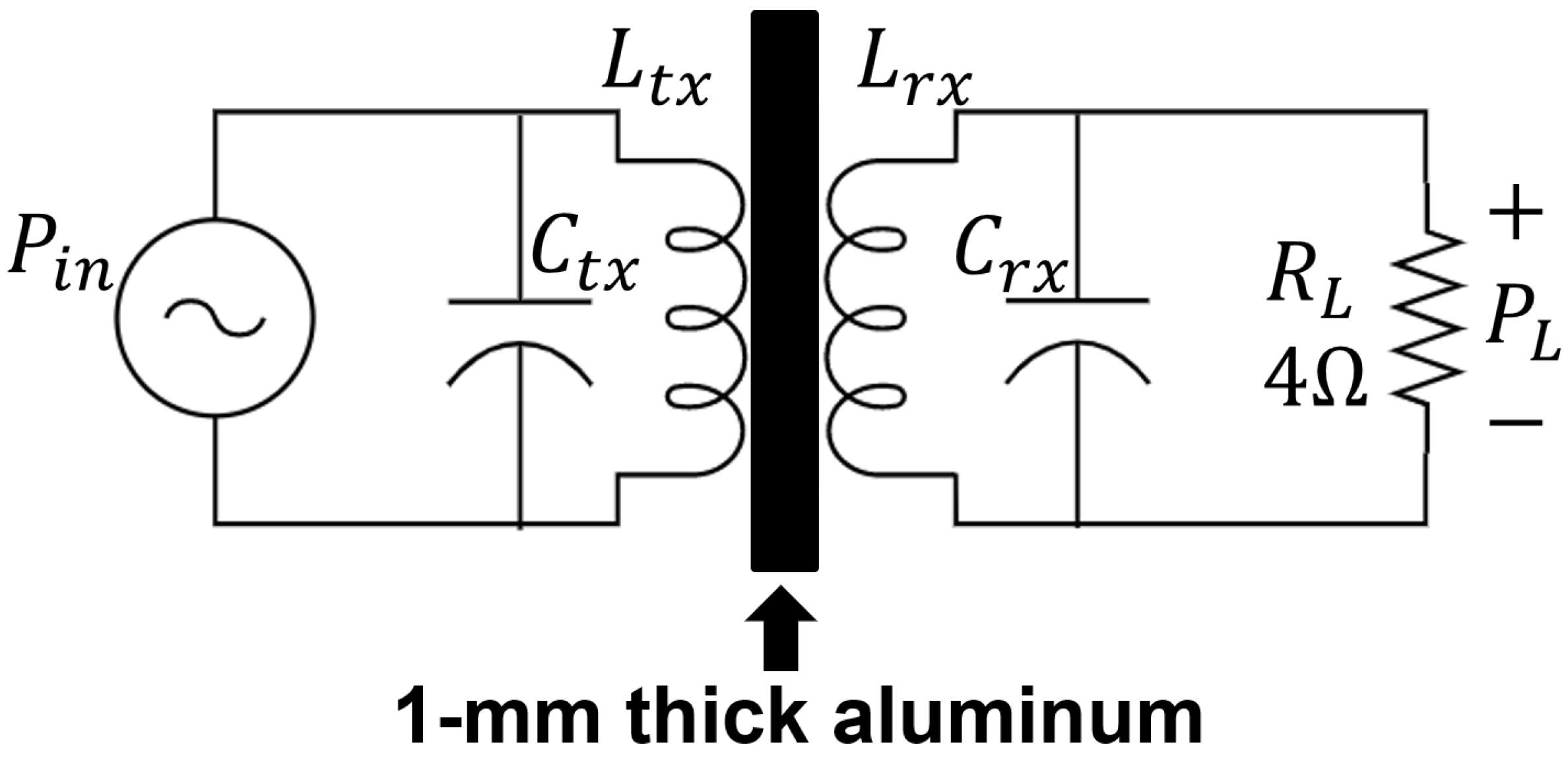
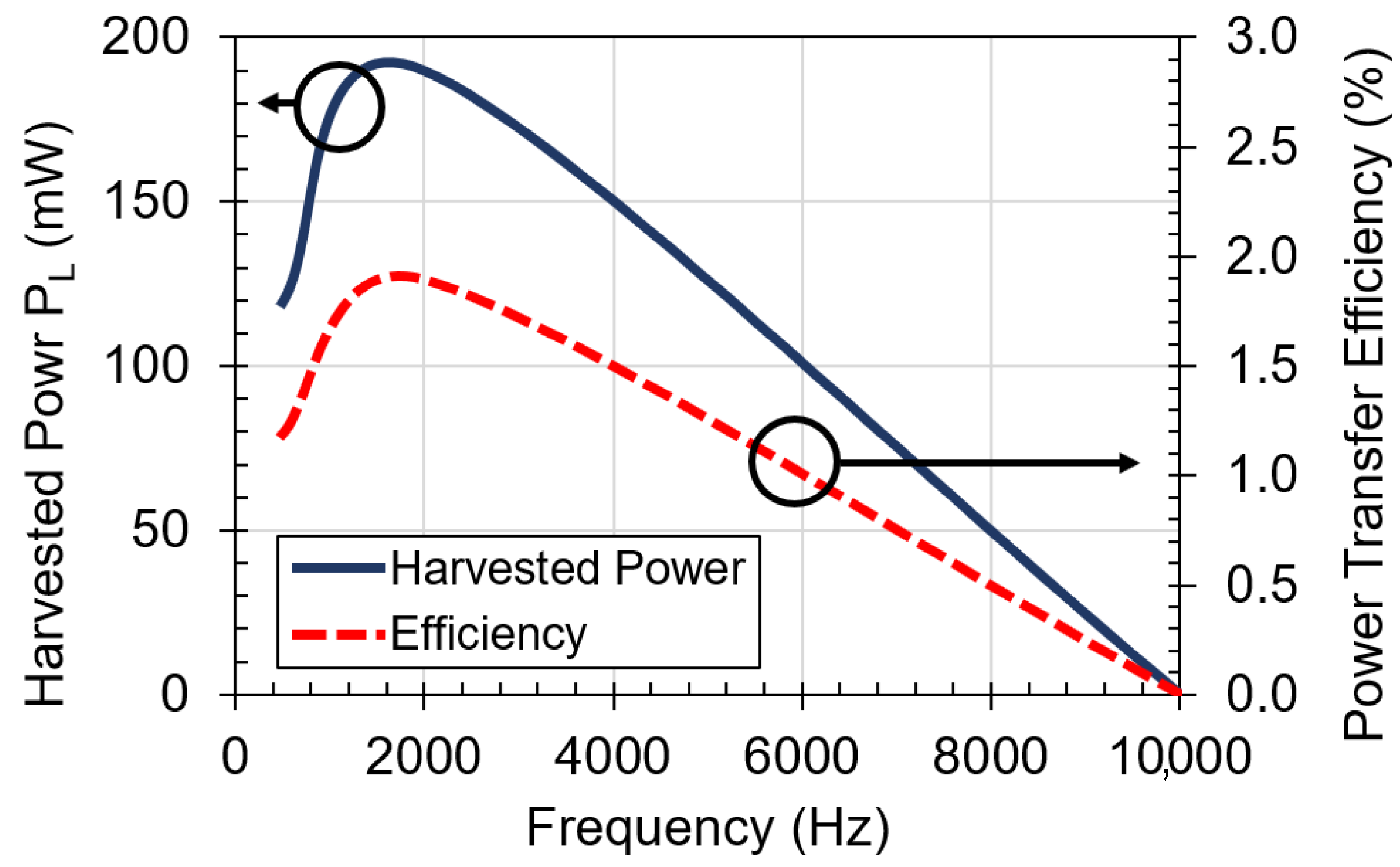
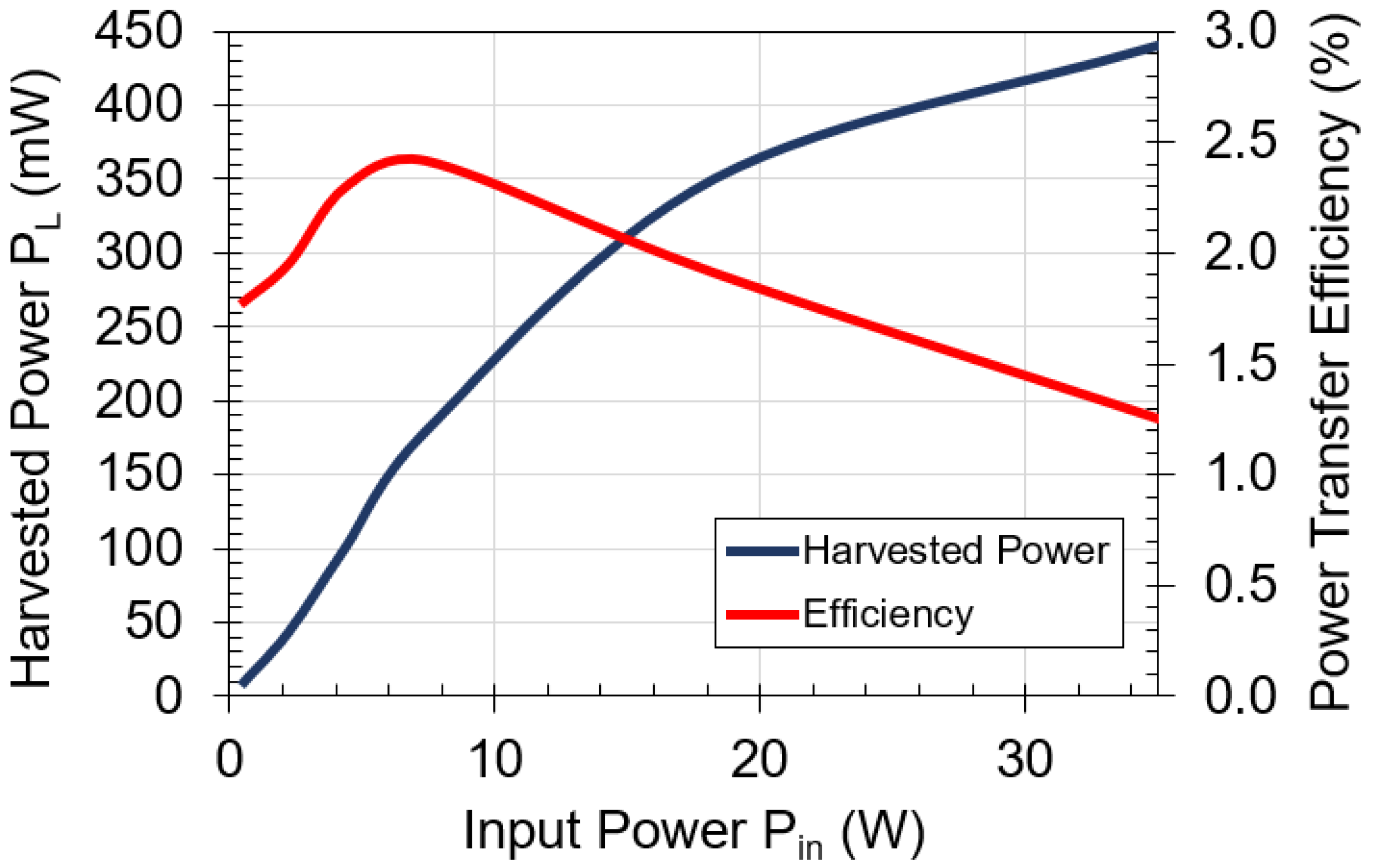
2.2. Load Effect
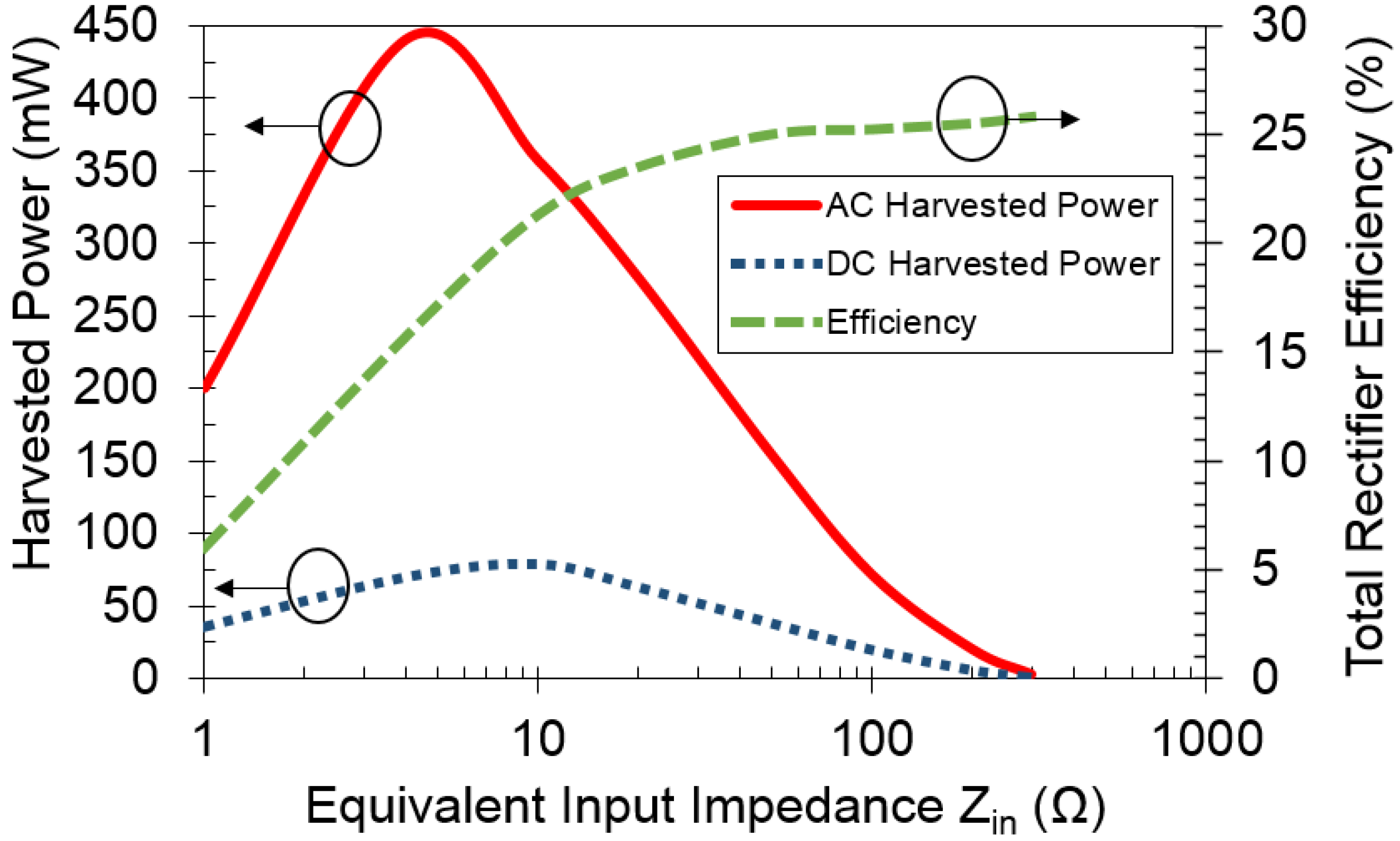
2.3. Coil Performance
3. Through Metal Scenarios
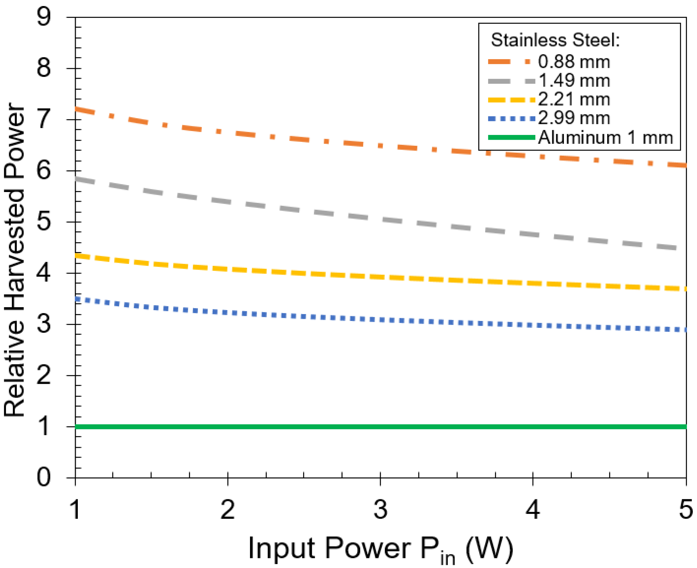
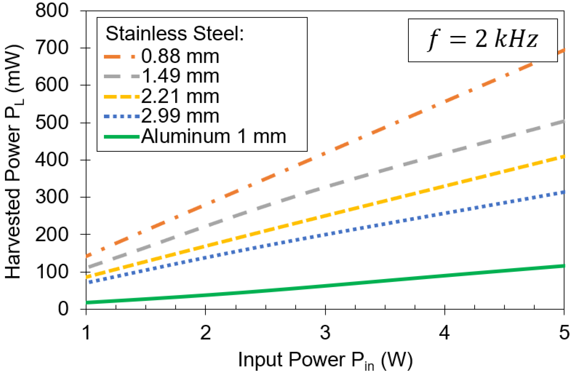
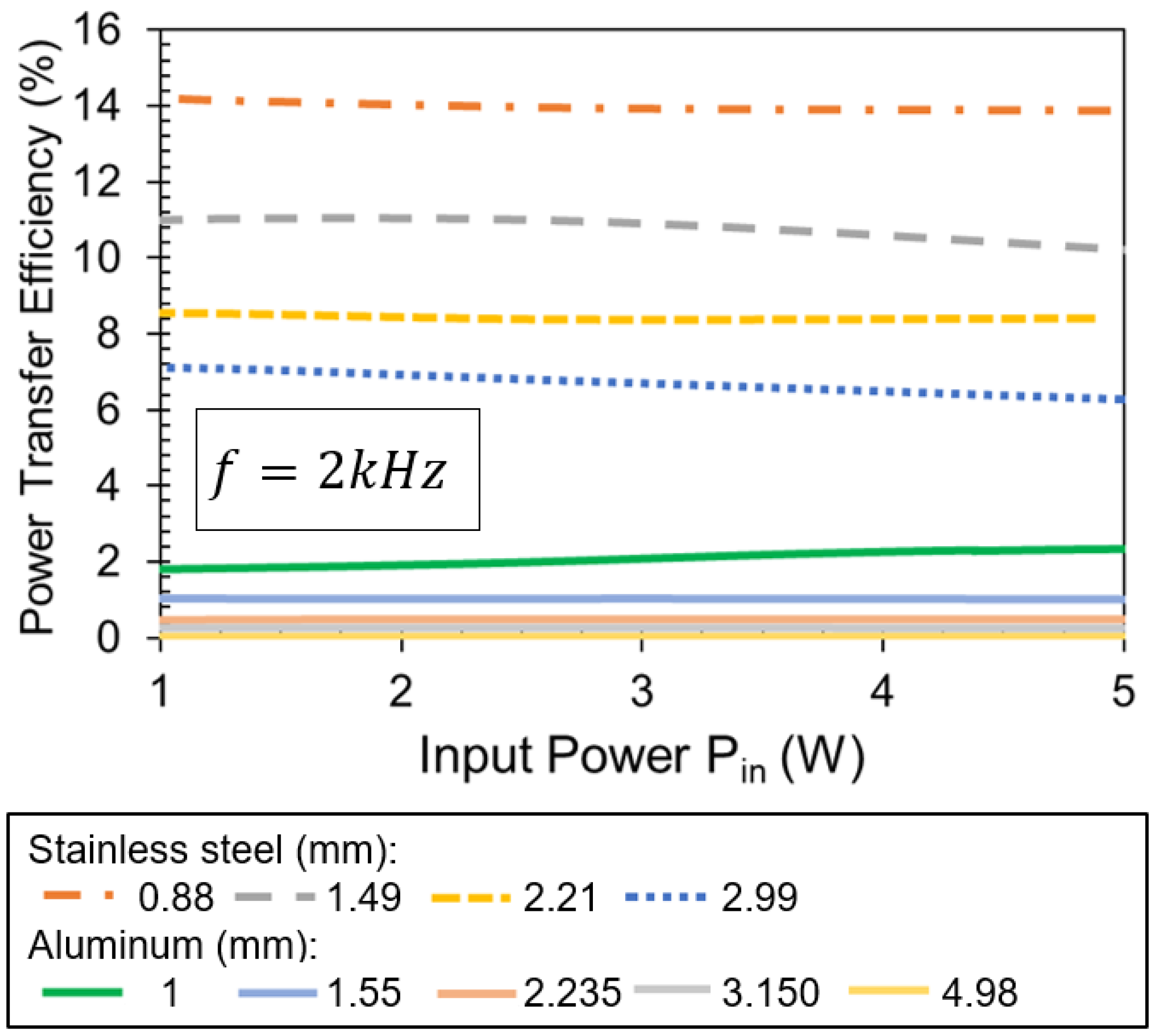
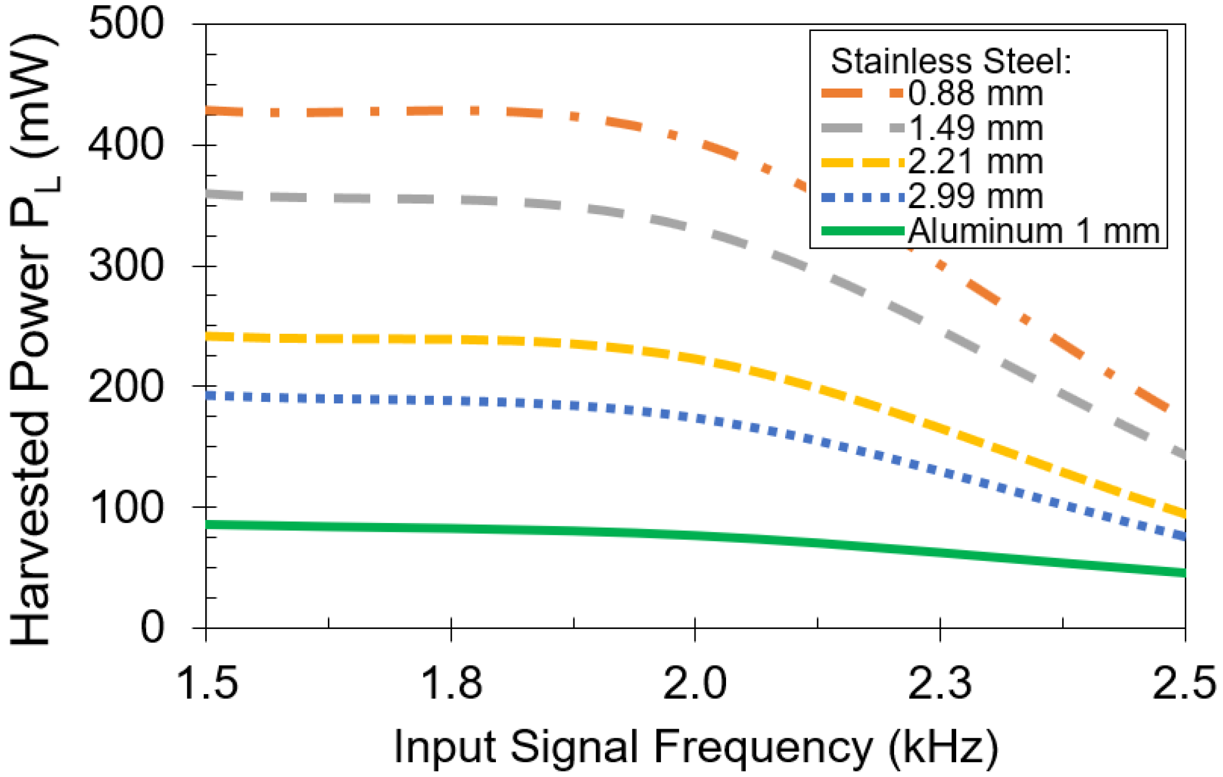
3.1. Stainless Steel
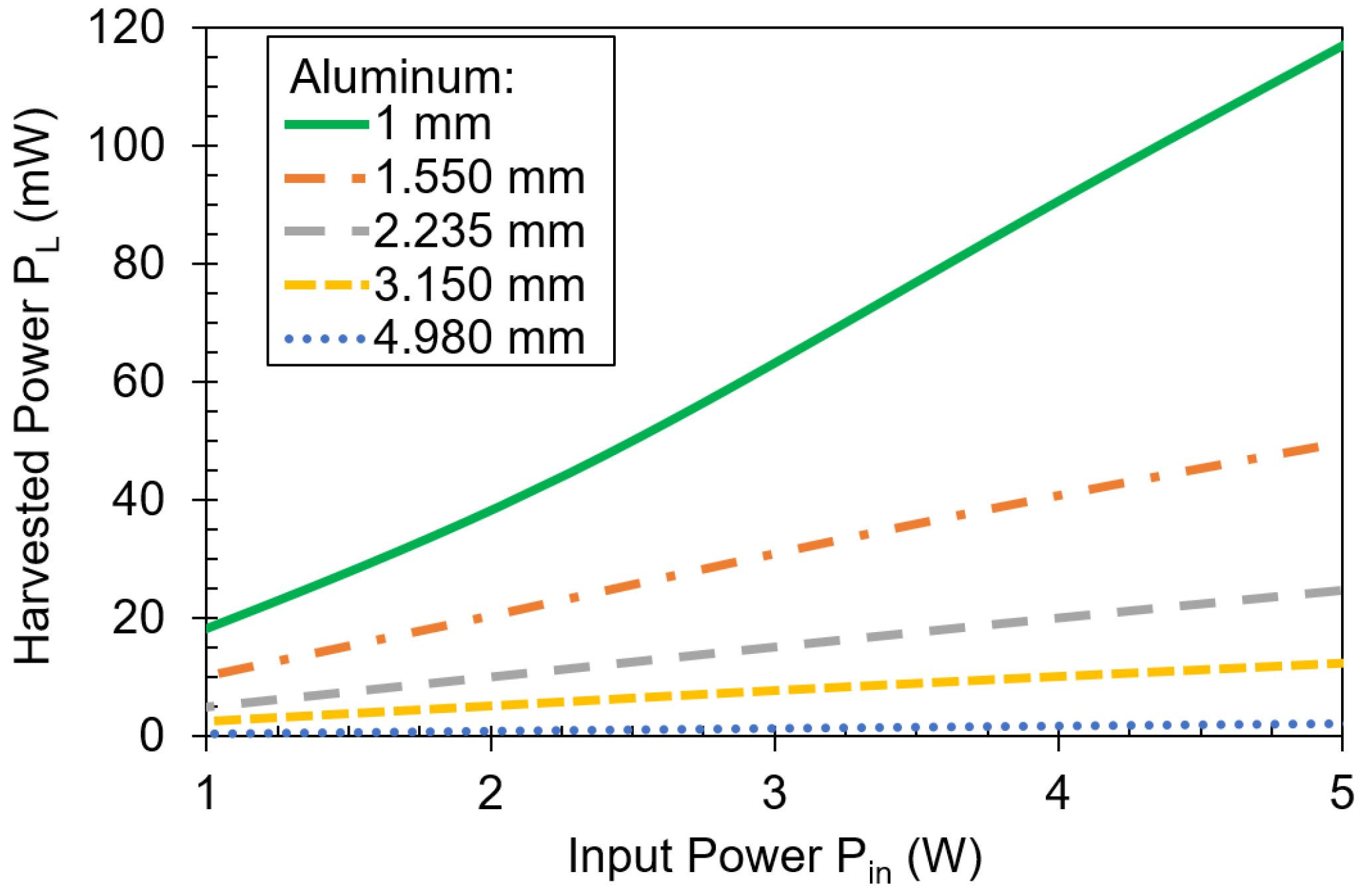
3.2. Aluminum
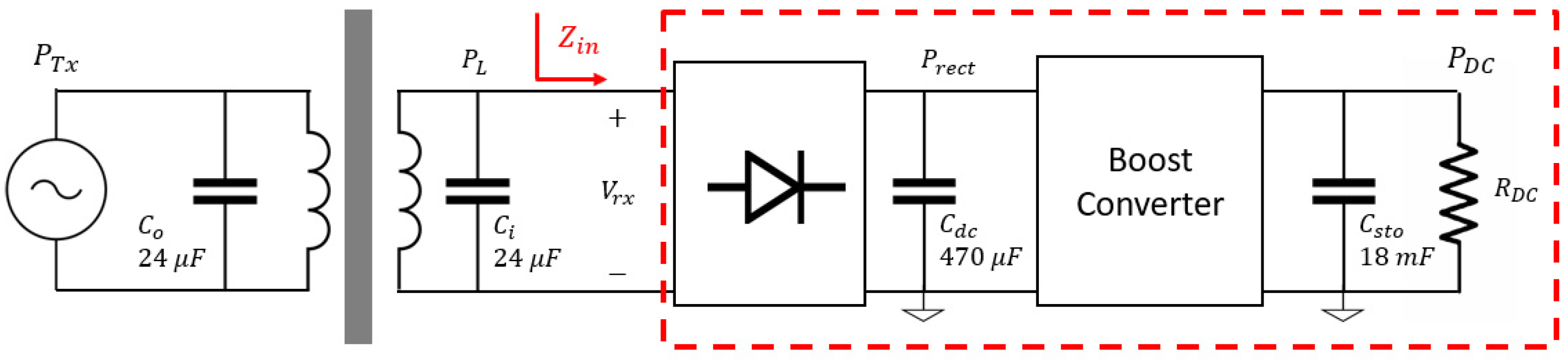
4. Through Metal Communication System
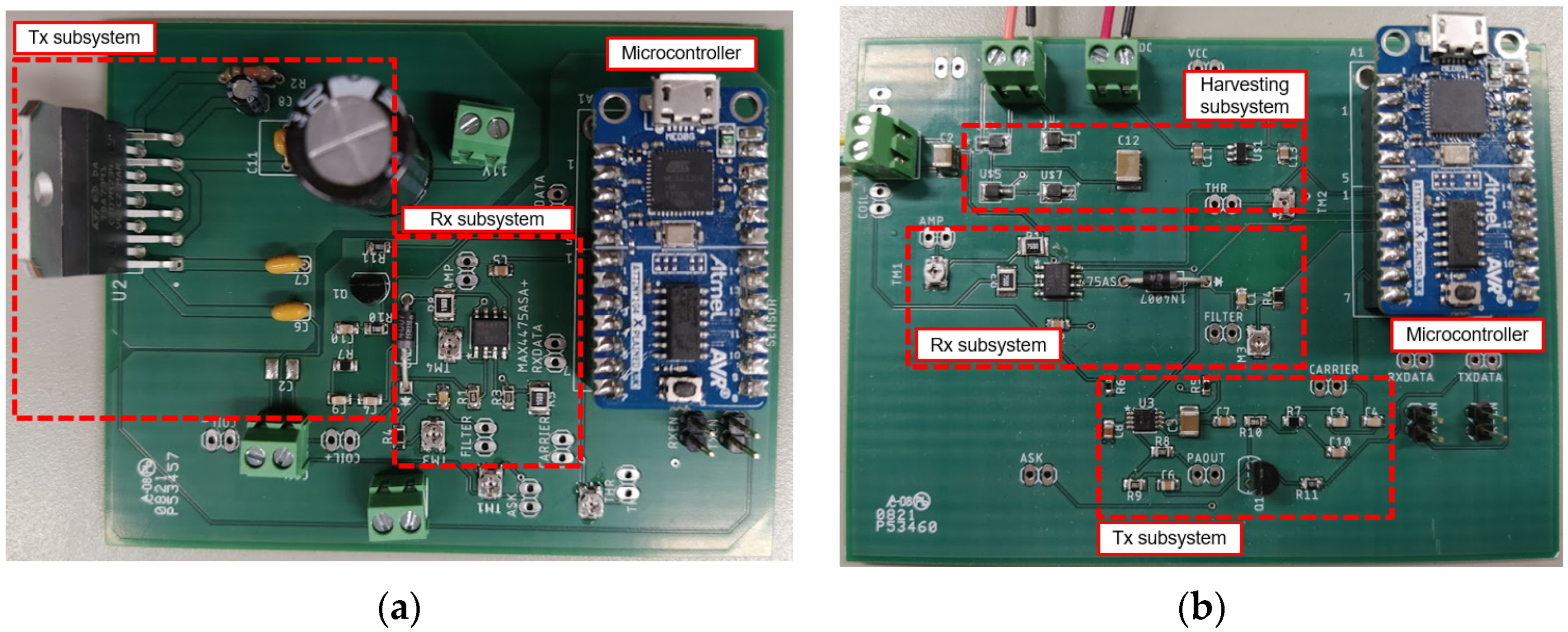
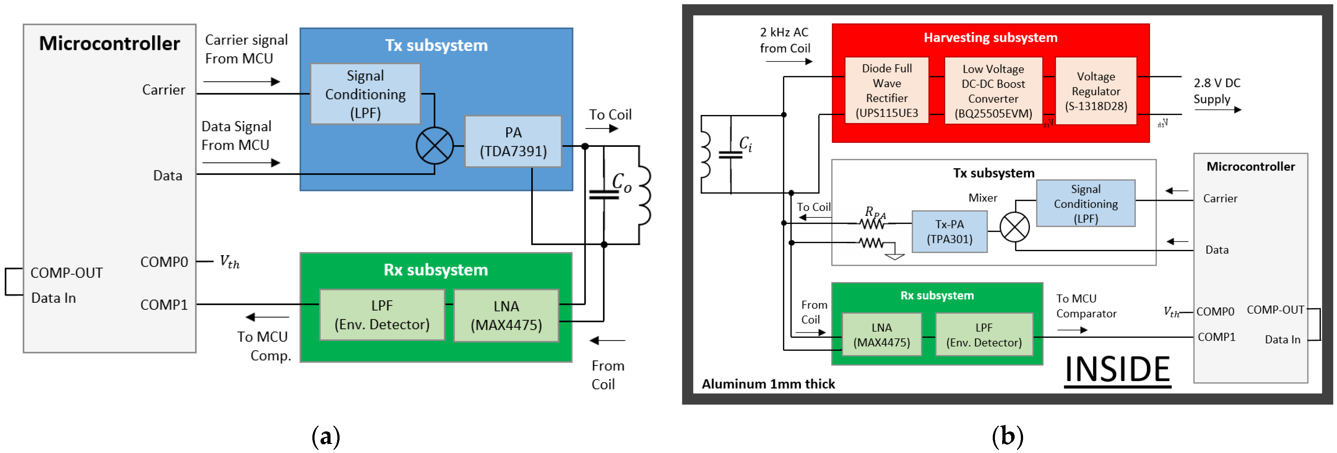
4.1. Outside Subsystem
4.2. Inside Subsystem
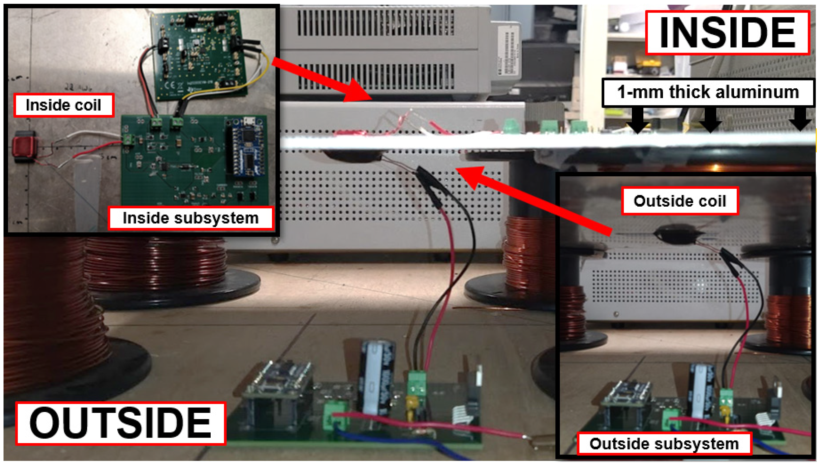
4.3. Prototype
- Outside subsystem enters WPT mode, and transmits a high-power signal to charge the inside subsystem through the 1 mm-thick aluminum plate.
- Inside subsystem harvests energy. If enough power is available, it enters Rx mode and waits for an incoming data stream from the outside subsystem, otherwise toggles between Sleep and Rx modes.
- Outside subsystem finishes its WPT mode and power transfer stops. Then, Tx mode begins and the outside subsystem transmits a data frame at a data rate of 100 bps.
- Inside subsystem is in Rx Mode and demodulates the incoming data. If data is received correctly, the inside subsystem enters Tx mode.
- Inside subsystem transmits data frame and goes back to Rx mode.
- Outside subsystem is in Rx mode. The data is received and demodulated.
- System is ready to start the cycle again.
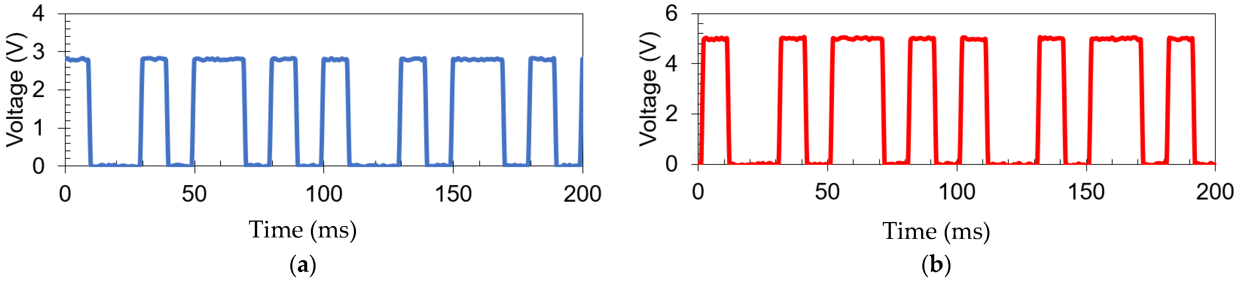
4.4. Experimental Validation
5. Conclusions
Author Contributions
Funding
Institutional Review Board Statement
Informed Consent Statement
Data Availability Statement
Conflicts of Interest
References
- Xie, L.; Shi, Y.; Hou, Y.T.; Lou, A. Wireless power transfer and applications to sensor networks. IEEE Wirel. Commun. 2013, 20, 140–145. [Google Scholar]
- Yang, D.X.; Hu, Z.; Zhao, H.; Hu, H.F.; Sun, Y.Z.; Hou, B.Y. Through-metal-wall power delivery and data transmission for enclosed sensors: A review. Sensors 2015, 15, 31581–31605. [Google Scholar] [CrossRef] [PubMed]
- Torres, O.; Nguyen, T.; Mackenzie, A. Enabling Wireless Avionics Intra-Communications; NASA: Hampton, VA, USA, December 2016. [Google Scholar]
- Yamakawa, M.; Mizuno, Y.; Ishida, J.; Komurasaki, K.; Koizumi, H. Wireless power transmission into a space enclosed by metal walls using magnetic resonance coupling. Wirel. Eng. Technol. 2014, 5, 19–24. [Google Scholar] [CrossRef] [Green Version]
- Vu, T.A.; Pham, C.V.; Tran, W.; Pham, A.V.; Gardner, C.S. Wireless power and data transfer through carbon composite using a common inductive link. Int. J. Power Electron. Drive Syst. (IJPEDS) 2020, 3, 1441–1448. [Google Scholar] [CrossRef]
- Alhamrouni, I.; Iskandar, M.; Salem, M.; Awalin, L.J.; Jusoh, A.; Sutikno, T. Application of inductive coupling for wireless power transfer. Int. J. Power Electron. Drive Syst. (IJPEDS) 2020, 11, 1109. [Google Scholar] [CrossRef]
- Jeong, N.S.; Carobolante, F. Enabling wireless power transfer though a metal encased handheld device. In Proceedings of the 2016 IEEE Wireless Power Transfer Conference (WPTC), Aveiro, Portugal, 5–6 May 2016. [Google Scholar]
- Jeong, N.S.; Carobolante, F. Wireless charging of a metal-body device. IEEE Trans. Microw. Theory Tech. 2017, 65, 1077–1086. [Google Scholar] [CrossRef]
- Zangl, H.; Fuchs, A.; Bretterklieber, T.; Moser, M.J.; Holler, G. Wireless Communication and Power Supply Strategy for Sensor Applications Within Closed Metal Walls. IEEE Trans. Instrum. Meas. 2020, 59, 1686–1692. [Google Scholar] [CrossRef]
- Pham, C.V.; Pham, A.V.; Gardner, C.S. Development of Helical circular coils for wireless through-metal inductive power transfer. In Proceedings of the 2017 IEEE Wireless Power Transfer Conference (WPTC), Taipei, Taiwan, 10–12 May 2017. [Google Scholar]
- Pham, C.V.; Vu, T.A.; Tran, W.; Pham, A.V.; Gardner, C.S. Wireless Energy Harvesting System Through Metal for Aerospace Sensor. In Proceedings of the 2018 IEEE Transportation Electrification Conference and Expo (ITEC), Long Beach, CA, USA, 13–15 June 2018. [Google Scholar]
- Vu, T.A.; Pham, C.V.; Pham, A.V.; Gardner, C.S. Wireless power transfer through metal using inductive link. Int. J. Power Electron. Drive Syst. (IJPEDS) 2019, 10, 1906–1913. [Google Scholar] [CrossRef]
- Zhou, W.; Su, Y.; Huang, L.; Qing, X.; Hu, A.P. Wireless Power Transfer Across a Metal Barrier by Combined Capacitive and Inductive Coupling. IEEE Trans. Ind. Electron. 2019, 66, 4031–4041. [Google Scholar] [CrossRef]
- Jawad, A.M.; Nordin, R.; Gharghan, S.K.; Jawad, H.M.; Ismail, M. Opportunities and challenges for near-field wireless power transfer: A review. Energies 2017, 10, 1022. [Google Scholar] [CrossRef]
- Romero-Arguello, J.M.; Pham, A.V.; Gardner, C.S.; Funsten, B. Miniature Coil Design for Through Metal Wireless Power Transfer. In Proceedings of the 2021 IEEE Wireless Power Transfer Conference (WPTC), San Diego, CA, USA, 1–4 June 2021. [Google Scholar]
- Liu, X.; Xia, C.; Yuan, X. Study of the circular flat spiral coil structure effect on wireless power transfer system performance. Energies 2018, 11, 2875. [Google Scholar] [CrossRef] [Green Version]
- Wang, M.; Feng, J.; Shi, Y.; Shen, M. Demagnetization weakening and magnetic field concentration with ferrite core characterization for efficient wireless power transfer. IEEE Trans. Ind. Electron. 2018, 66, 1842–1851. [Google Scholar] [CrossRef]
- Babatunde, O.; Partridge, J.; Bucknall, R. Finite Element Modeling and Analysis of High Power, Low-loss Flux-Pipe Resonant Coils for Static Bidirectional Wireless Power Transfer. Energies 2019, 12, 3534. [Google Scholar]
- 43 Material Data Sheet. Available online: https://www.fair-rite.com/43-material-data-sheet/ (accessed on 19 October 2021).
- Li, J.; Huang, X.; Chen, C.; Tan, L.; Wang, W.; Guo, J. Effect of metal shielding on a wireless power transfer system. AIP Adv. 2017, 7, 056675. [Google Scholar] [CrossRef]
- Allamehzadeh, H. Wireless Power Transfer (WPT) Fundamentals with Resonant Frequency-Dependent Parameters, Energy Transfer Efficiency, and Green Technology Applications. In Proceedings of the 2021 IEEE 48th Photovoltaic Specialists Conference (PVSC), Lauderdale, FL, USA, 20–25 June 2021. [Google Scholar]
- Chen, Y.S.; Chiu, C.W. Theoretical limits of rectifying efficiency for low-power wireless power transfer. Int. J. RF Microw. Comput.-Aided Eng. 2018, 28, e21218. [Google Scholar] [CrossRef]
- Jiang, C.; Chau, K.T.; Liu, C.; Lee, C.H. An overview of resonant circuits for wireless power transfer. Energies 2017, 10, 894. [Google Scholar] [CrossRef]
- Noghabaei, S.M.; Radin, R.L.; Savaria, Y.; Sawan, M. A high-efficiency ultra-low-power CMOS rectifier for RF energy harvesting applications. In Proceedings of the 2018 IEEE International Symposium on Circuits and Systems (ISCAS), Florence, Italy, 27–30 May 2018. [Google Scholar]
- Wire Gauge and Current Limits Including Skin Depth and Strength. Available online: https://www.powerstream.com/Wire_Size.htm (accessed on 8 November 2021).
- Magnet Wire, 200C, 24 AWG Polyamideimide. Available online: https://www.remingtonindustries.com/magnet-wire/magnet-wire-200c-24-awg-polyamideimide-7-spool-sizes/ (accessed on 8 November 2021).
- Graham, D.J.; Neasham, J.A.; Sharif, B.S. Investigation of Methods for Data Communication and Power Delivery Through Metals. IEEE Trans. Ind. Electron. 2011, 58, 4972–4980. [Google Scholar] [CrossRef]
- Imoru, O.; Jassal, A.; Polinder, H.; Nieuwkoop, E.; Tsado, J.; Jimoh, A.A. An Inductive Power Transfer through metal object. In Proceedings of the 2013 1st International Future Energy Electronics Conference (IFEEC), Tainan City, Taiwan, 3–6 November 2013. [Google Scholar]
- Mitchell, B.S. Appendix 8: Electrical Conductivity of Selected Materials. In An Introduction to Materials Engineering and Science for Chemical and Materials Engineers; John Wiley & Sons: Hoboken, NJ, USA, 2004; pp. 893–894. [Google Scholar]
- Chung, D.D. Materials for electromagnetic interference shielding. Mater. Chem. Phys. 2020, 255, 123587. [Google Scholar] [CrossRef]
- Inan, U.; Inan, A. Plane Waves in Lossy Media. In Electromagnetics Waves; Prentice Hall: Upper Saddle River, NJ, USA, 1999; pp. 38–55. [Google Scholar]
- Hui, S.Y.R. Magnetic Resonance for Wireless Power Transfer. IEEE Power Electron. Mag. 2016, 3, 14–31. [Google Scholar] [CrossRef] [Green Version]
- Starrett, C.E.; Perriot, R.; Shaffer, N.R.; Nelson, T.; Collins, L.A.; Ticknor, C. Tabular electrical conductivity for aluminium. Contrib. Plasma Phys. 2020, 60, e201900123. [Google Scholar] [CrossRef]
- Middlestead, R.W. Amplitude shift keying modulation, demodulation, and performance. In Digital Communications with Emphasis on Data Modems: Theory, Analysis, Design, Simulation, Testing, and Applications; Wiley: Hoboken, NJ, USA, 2017; pp. 227–250. [Google Scholar]
- Huang, Y.; Shinohara, N.; Mitani, T. Impedance matching in wireless power transfer. IEEE Trans. Microw. Theory Tech. 2016, 65, 582–590. [Google Scholar] [CrossRef]


| Frequency (kHz) | Inductance L (µH) | Quality Factor Q |
|---|---|---|
| 1 | 301.9 | 4.195 |
| 10 | 303.5 | 34.75 |
| Reference | Coil Size (mm) | Metal Barrier Thickness | Harvested Power (mW) | Coil Power Transfer Efficiency (%) | Frequency (Hz) | Volume (mm3) |
|---|---|---|---|---|---|---|
| [9] | 30 × Ø30 | Tin 0.5 mm | 0.03 | - | 50 | 21,205 |
| [4] | 234 × 67 × 30 | Stainless steel 1.6 mm | 3000 | 43 | 50 | 470,340 |
| [27] | 80 × Ø240 | Aluminum 4 mm | 18,181 | 23 | 100 | 3,619,114 |
| [28] | 8 × Ø115 | Stainless Steel 20 mm | 7000 | 5.5 | 500 | 83,095 |
| [12] | 50 × Ø98 | Aluminum 3.1 mm | 5000 | 9 | 250 | 377,148 |
| This work | 15 × 13 × 6 | Aluminum 1 mm | 440 | 2.5 | 2000 | 1170 |
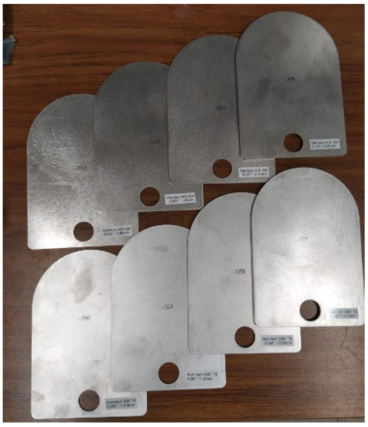
| Stainless Steel AISI 304 Thickness (mm) | Aluminum 6061T6 Thickness (mm) |
|---|---|
| 0.88 | 1.55 |
| 1.49 | 2.235 |
| 2.21 | 3.15 |
| 2.99 | 4.98 |
Publisher’s Note: MDPI stays neutral with regard to jurisdictional claims in published maps and institutional affiliations. |
© 2021 by the authors. Licensee MDPI, Basel, Switzerland. This article is an open access article distributed under the terms and conditions of the Creative Commons Attribution (CC BY) license (https://creativecommons.org/licenses/by/4.0/).
Share and Cite
Romero-Arguello, J.M.; Pham, A.-V.; Gardner, C.S.; Funsten, B.T. Miniature Coil for Wireless Power and Data Transfer through Aluminum. Sensors 2021, 21, 7573. https://doi.org/10.3390/s21227573
Romero-Arguello JM, Pham A-V, Gardner CS, Funsten BT. Miniature Coil for Wireless Power and Data Transfer through Aluminum. Sensors. 2021; 21(22):7573. https://doi.org/10.3390/s21227573
Chicago/Turabian StyleRomero-Arguello, Juan M., Anh-Vu Pham, Christopher S. Gardner, and Brad T. Funsten. 2021. "Miniature Coil for Wireless Power and Data Transfer through Aluminum" Sensors 21, no. 22: 7573. https://doi.org/10.3390/s21227573
APA StyleRomero-Arguello, J. M., Pham, A.-V., Gardner, C. S., & Funsten, B. T. (2021). Miniature Coil for Wireless Power and Data Transfer through Aluminum. Sensors, 21(22), 7573. https://doi.org/10.3390/s21227573