
Custom IMU-Based Wearable System for Robust 2.4 GHz Wireless Human Body Parts Orientation Tracking and 3D Movement Visualization on an Avatar

 , , and
Abstract
:1. Introduction
2. Materials and Methods
2.1. Hardware
2.2. Communication
2.3. Body Parts Orientation Tracking and 3D Movement Visualization
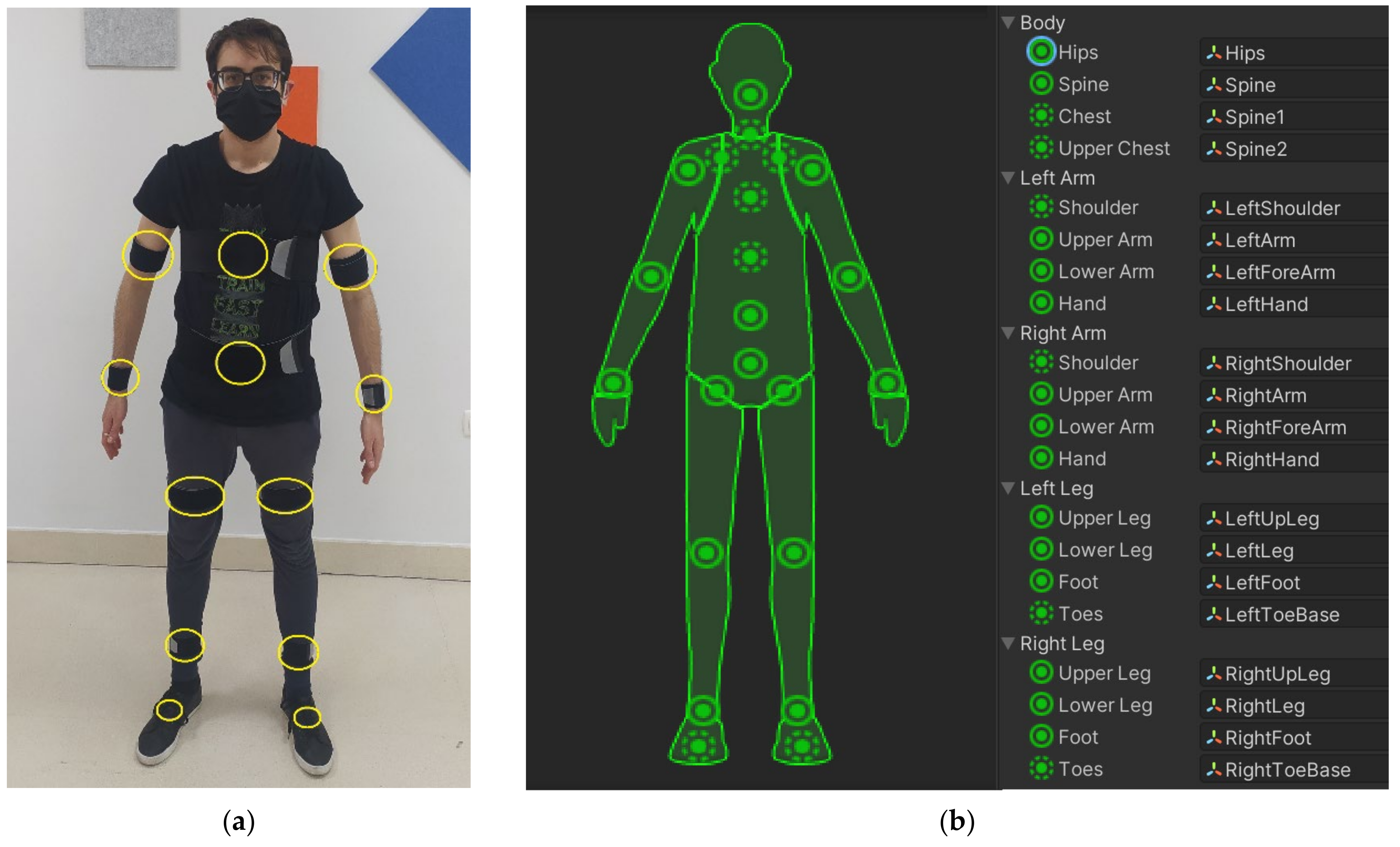
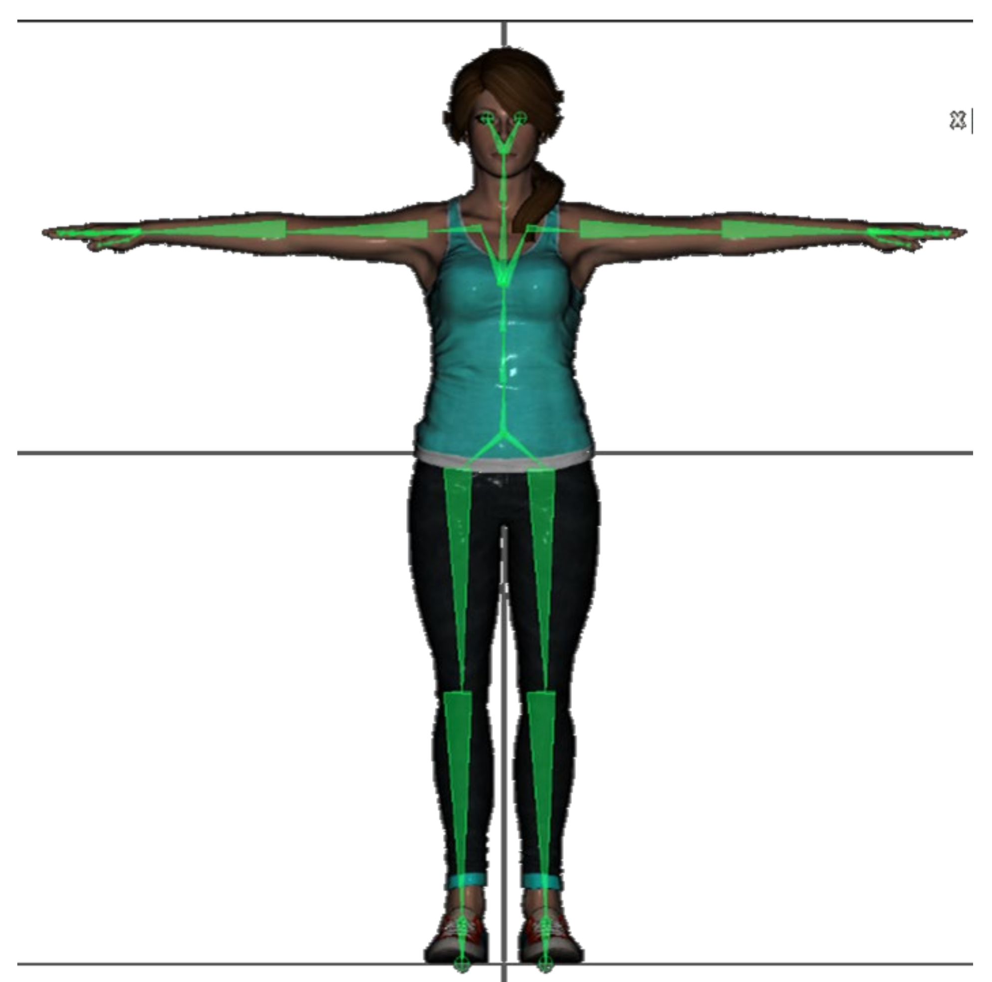
- The subject is asked to adopt a calibration body pose (the Unity3D app offers the user to adopt a neutral pose or a T-pose as Figure 6 shows). The instant rotation of the attached CW sensor is stored as the initial orientation . Then, the new relative orientation of the sensor in the IMUs global space , with respect to its initial orientation, can be computed using equation (2), where denotes the inverse of the initial orientation of the sensor in the human body pose adopted during the I2S procedure.
- Since the CW sensors and the Unity3D environment do not use the same coordinate reference system, a translation is needed to adapt the raw data acquired by the sensors to the left-handed system adopted in the Unity3D application, using Equation (3), where is now the relative orientation of the IMU in the Unity3D space.
- During the calibration procedure, the initial rotation of the humanoid bones in the chosen initial pose is also considered. The avatar can be animated in real-time by rotating the humanoid bones according to Equation (3), in which denotes the instant rotation of the bone in the Unity3D global coordinate system.
2.4. Limitations of the Chosen Kinematic Model
3. Experiments and Results
3.1. Validation of I2S and Body Parts Orientation Tracking
3.1.1. Static Test
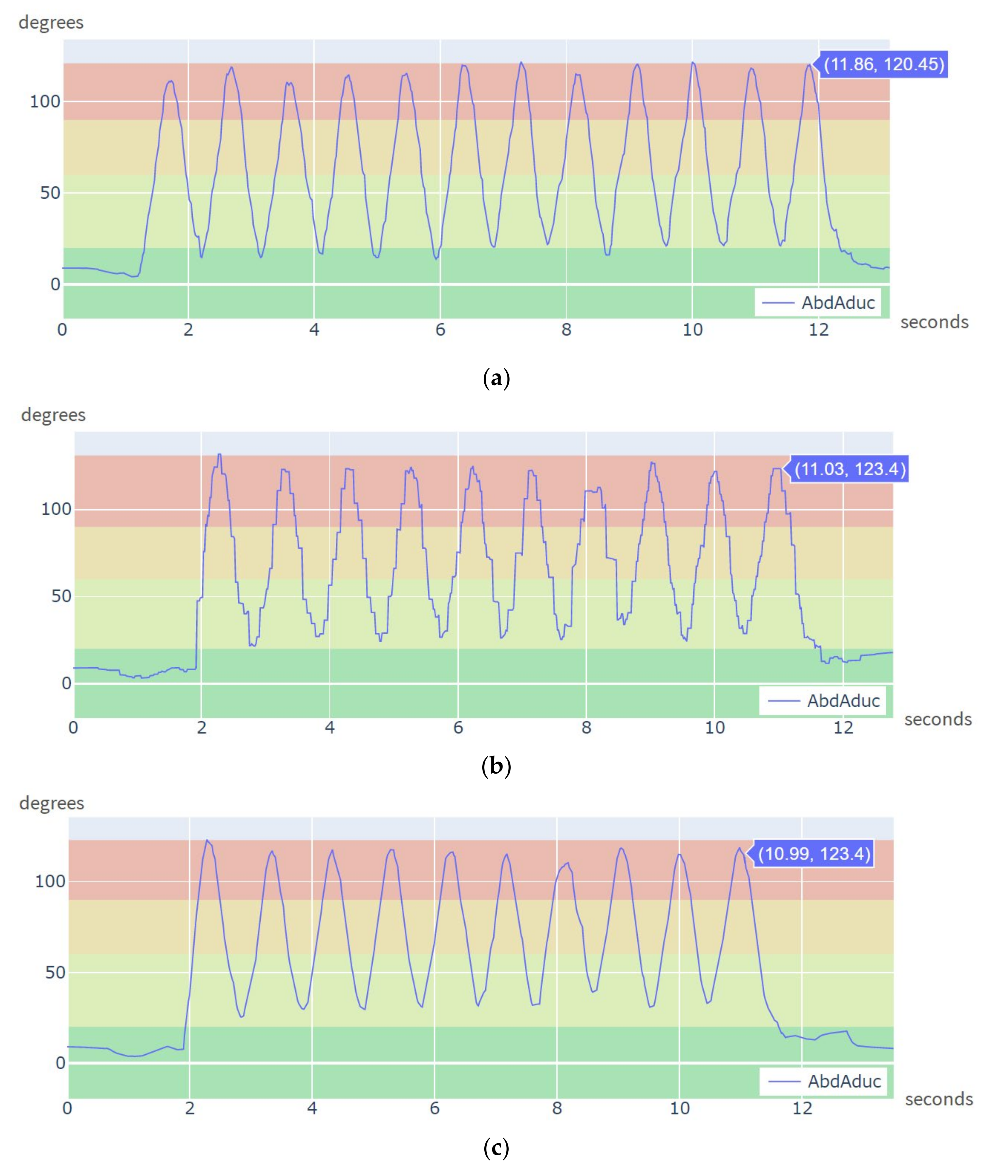
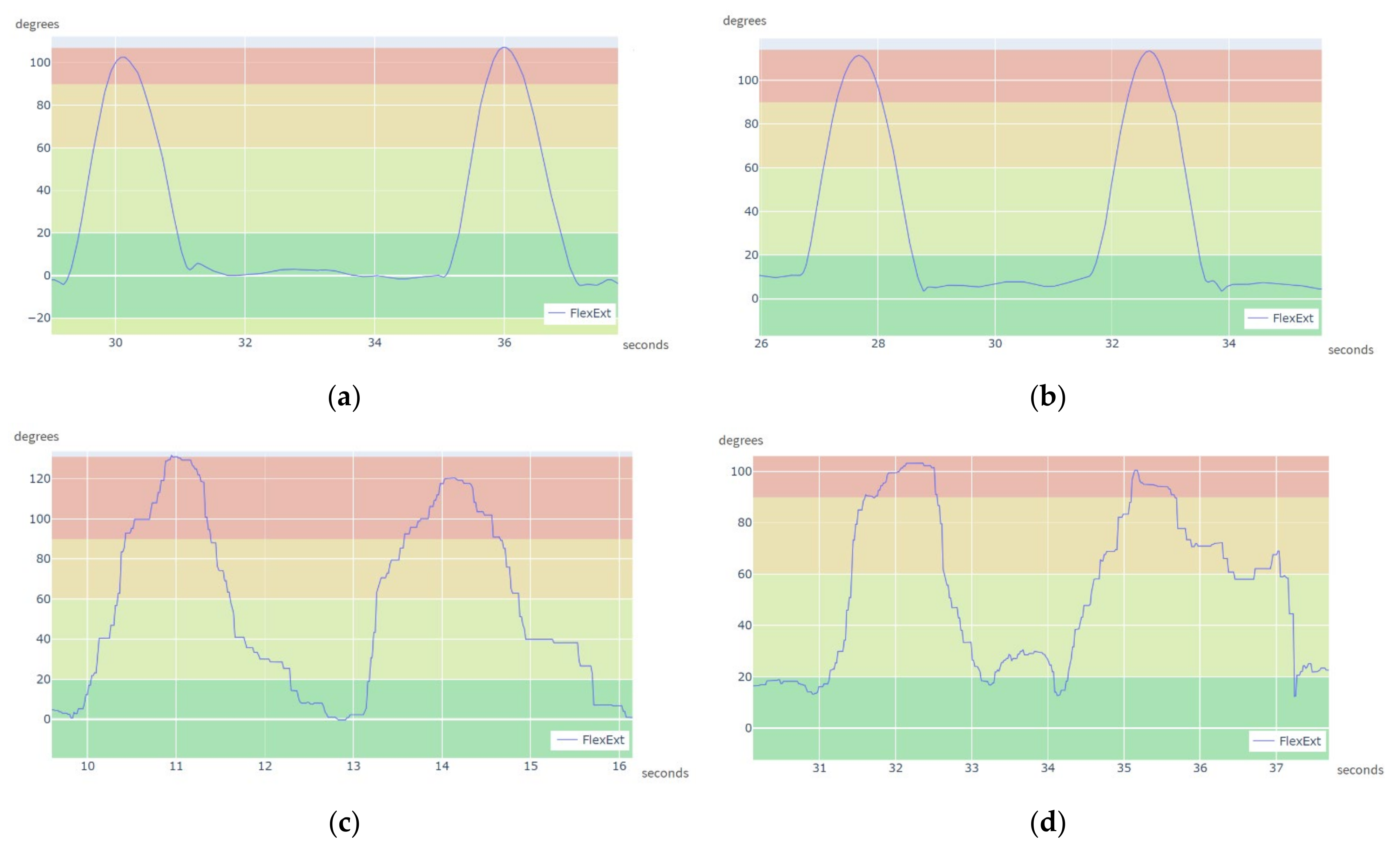
3.1.2. Dynamic Test
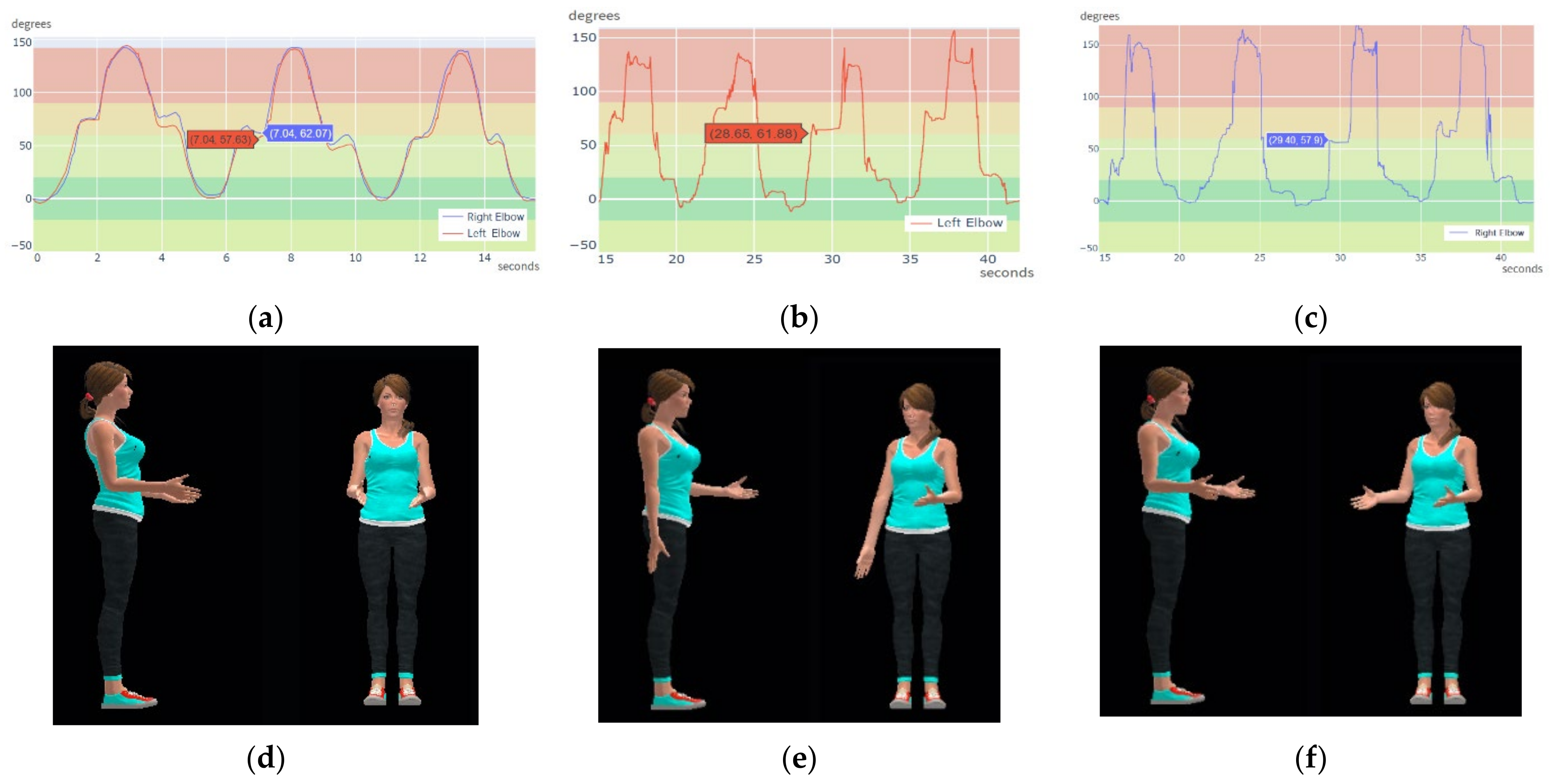
3.2. Experiments Capturing Human Motion with Multiple CW Sensors
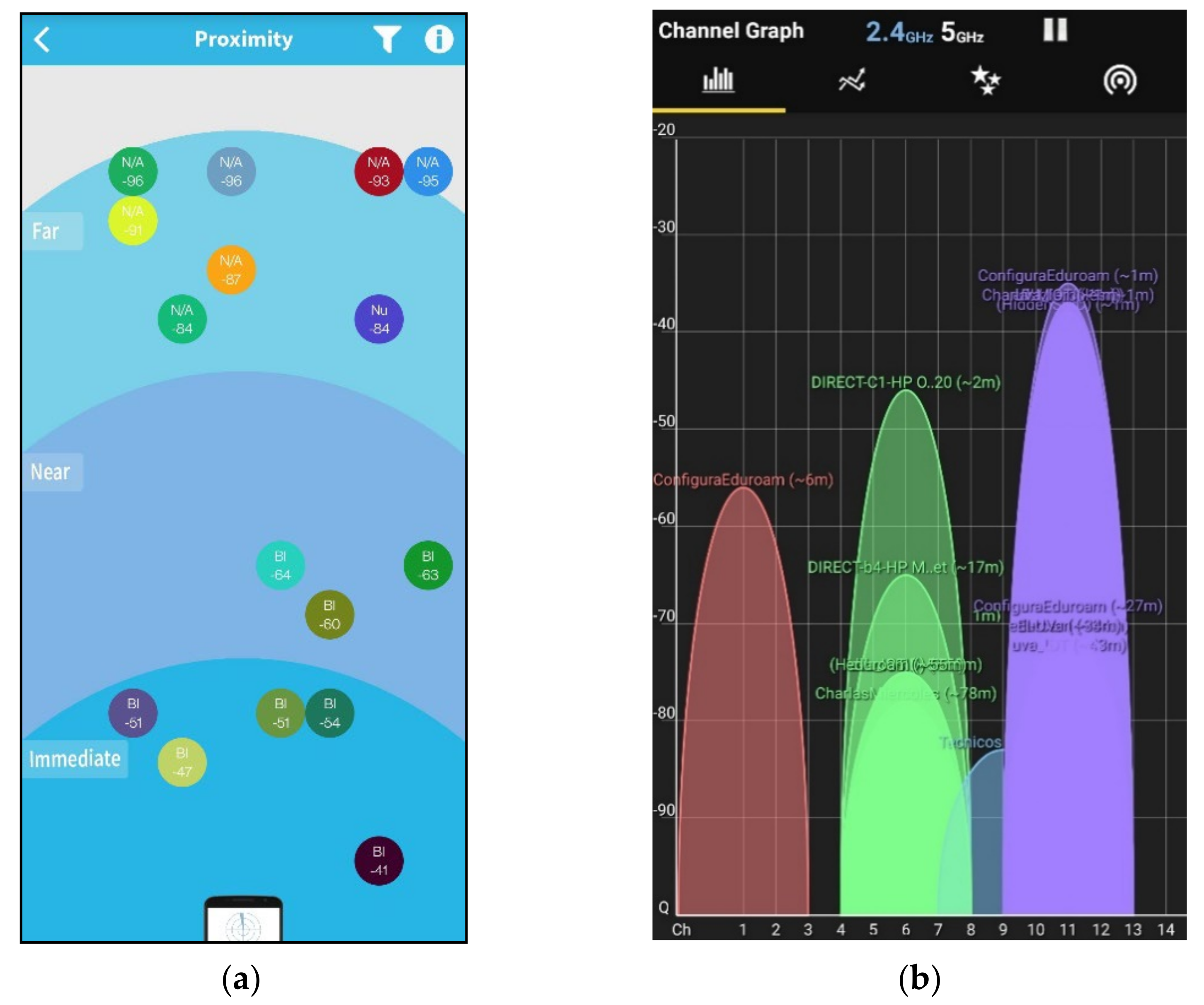
3.3. Robust Communication in Bluetooth and Wi-Fi Crowded Environments
4. Discussion
5. Conclusions
Supplementary Materials
Author Contributions
Funding
Institutional Review Board Statement
Informed Consent Statement
Conflicts of Interest
References
- López-Nava, I.H.; Muñoz-Meléndez, A. Wearable Inertial Sensors for Human Motion Analysis: A Review. IEEE Sens. J. 2016, 16, 7821–7834. [Google Scholar] [CrossRef]
- Porciuncula, F.; Roto, A.V.; Kumar, D.; Davis, I.; Roy, S.; Walsh, C.J.; Awad, L.N. Wearable Movement Sensors for Rehabilita-tion: A Focused Review of Technological and Clinical Advances. PM&R 2018, 10, S220–S232. [Google Scholar] [CrossRef] [Green Version]
- Díaz Hernández, S.; Stephenson, J.; Labrador, M. Use of Wearable Sensor Technology in Gait, Balance, and Range of Motion Analysis. Appl. Sci. 2019, 10, 234. [Google Scholar] [CrossRef] [Green Version]
- Aminian, K.; Robert, P.; Buchser, E.E.; Rutschmann, B.; Hayoz, D.; Depairon, M. Physical Activity Monitoring Based on Accelerometry: Validation and Comparison with Video Observation. Med. Biol. Eng. Comput. 1999, 37, 304–308. [Google Scholar] [CrossRef]
- Zhou, H.; Hu, H. Reducing Drifts in the Inertial Measurements of Wrist and Elbow Positions. IEEE Trans. Instrum. Meas. 2010, 59, 575–585. [Google Scholar] [CrossRef]
- Narasimhappa, M.; Mahindrakar, A.D.; Guizilini, V.C.; Terra, M.H.; Sabat, S.L. MEMS-Based IMU Drift Minimization: Sage Husa Adaptive Robust Kalman Filtering. IEEE Sens. J. 2020, 20, 250–260. [Google Scholar] [CrossRef]
- Wittmann, F.; Lambercy, O.; Gassert, R. Magnetometer-Based Drift Correction During Rest in IMU Arm Motion Tracking. Sensors 2019, 19, 1312. [Google Scholar] [CrossRef] [Green Version]
- Robert-Lachaine, X.; Mecheri, H.; Larue, C.; Plamondon, A. Validation of Inertial Measurement Units with an Optoelectronic System for Whole-Body Motion Analysis. Med. Biol. Eng. Comput. 2017, 55, 609–619. [Google Scholar] [CrossRef]
- Özkaya, N.; Nordin, M.; Goldsheyder, D.; Leger, D. Fundamentals of Biomechanics: Equilibrium, Motion, and Deformation, 3rd ed.; Springer: New York, NY, USA, 2012; ISBN 978-1-4899-9378-6. [Google Scholar]
- Álvarez, D.; Alvarez, J.C.; González, R.C.; López, A.M. Upper Limb Joint Angle Measurement in Occupational Health. Comp. Methods Biomech. Biomed. Eng. 2016, 19, 159–170. [Google Scholar] [CrossRef]
- Liu, L.; Wang, H.-H.; Qiu, S.; Zhang, Y.-C.; Hao, Z.-D. Paddle Stroke Analysis for Kayakers Using Wearable Technologies. Sensors 2021, 21, 914. [Google Scholar] [CrossRef] [PubMed]
- Stanzani, R.; Dondero, P.; Mantero, A.; Testa, M. Measurement Accuracy of an Upper Limb Tracking System Based on Two Hillcrest Labs BNO080 IMU Sensors: An Environmental Assessment. IEEE Sens. J. 2020, 20, 10267–10274. [Google Scholar] [CrossRef]
- Crabolu, M.; Pani, D.; Raffo, L.; Conti, M.; Crivelli, P.; Cereatti, A. In Vivo Estimation of the Shoulder Joint Center of Rotation Using Magneto-Inertial Sensors: MRI-Based Accuracy and Repeatability Assessment. Biomed. Eng. Online 2017, 16, 34. [Google Scholar] [CrossRef] [Green Version]
- Abhayasinghe, N.; Murray, I.; Sharif Bidabadi, S. Validation of Thigh Angle Estimation Using Inertial Measurement Unit Data against Optical Motion Capture Systems. Sensors 2019, 19, 596. [Google Scholar] [CrossRef] [Green Version]
- O’Reilly, M.; Caulfield, B.; Ward, T.; Johnston, W.; Doherty, C. Wearable Inertial Sensor Systems for Lower Limb Exercise Detection and Evaluation: A Systematic Review. Sports Med. 2018, 48, 1221–1246. [Google Scholar] [CrossRef] [Green Version]
- Chiang, C.-Y.; Chen, K.-H.; Liu, K.-C.; Hsu, S.J.-P.; Chan, C.-T. Data Collection and Analysis Using Wearable Sensors for Monitoring Knee Range of Motion after Total Knee Arthroplasty. Sensors 2017, 17, 418. [Google Scholar] [CrossRef]
- Aqueveque, P.; Gómez, B.A.; Saavedra, F.; Canales, C.; Contreras, S.; Ortega-Bastidas, P.; Cano-de-la-Cuerda, R. Validation of a Portable System for Spatial-Temporal Gait Parameters Based on a Single Inertial Measurement Unit and a Mobile Application. Eur. J. Transl. Myol. 2020, 30, 268–276. [Google Scholar] [CrossRef]
- Sánchez Manchola, M.D.; Bernal, M.J.P.; Munera, M.; Cifuentes, C.A. Gait Phase Detection for Lower-Limb Exoskeletons Using Foot Motion Data from a Single Inertial Measurement Unit in Hemiparetic Individuals. Sensors 2019, 19, 2988. [Google Scholar] [CrossRef] [Green Version]
- Taylor, L.; Miller, E.; Kaufman, K.R. Static and Dynamic Validation of Inertial Measurement Units. Gait Posture 2017, 57, 80–84. [Google Scholar] [CrossRef] [PubMed]
- Oarde, D.E.; Libatique, N.C.; Tangonan, G.L.; Sotto, D.M.; Pacaldo, A.T. Digital Motion Analysis System for Rehabilitation Using Wearable Sensors. In Proceedings of the 2014 International Conference on Humanoid, Nanotechnology, Information Technology, Communication and Control, Environment and Management (HNICEM), Palawan, Philippines, 12–16 November 2014; pp. 1–7. [Google Scholar] [CrossRef]
- Picerno, P.; Viero, V.; Donati, M.; Triossi, T.; Tancredi, V.; Melchiorri, G. Ambulatory Assessment of Shoulder Abduction Strength Curve Using a Single Wearable Inertial Sensor. J. Rehabil. Res. Dev. 2015, 52, 171–180. [Google Scholar] [CrossRef]
- Panwar, M.; Biswas, D.; Bajaj, H.; Jobges, M.; Turk, R.; Maharatna, K.; Acharyya, A. Rehab-Net: Deep Learning Framework for Arm Movement Classification Using Wearable Sensors for Stroke Rehabilitation. IEEE Trans. Biomed. Eng. 2019, 66, 3026–3037. [Google Scholar] [CrossRef]
- Adcock, M.; Fankhauser, M.; Post, J.; Lutz, K.; Zizlsperger, L.; Luft, A.R.; Guimarães, V.; Schättin, A.; de Bruin, E.D. Effects of an In-Home Multicomponent Exergame Training on Physical Functions, Cognition, and Brain Volume of Older Adults: A Randomized Controlled Trial. Front. Med. 2020, 6, 321. [Google Scholar] [CrossRef]
- Yang, P.; Xie, L.; Wang, C.; Lu, S. IMU-Kinect: A Motion Sensor-Based Gait Monitoring System for Intelligent Healthcare. In Proceedings of the 2019 ACM International Joint Conference on Pervasive and Ubiquitous Computing and Proceedings of the 2019 ACM International Symposium on Wearable Computers—UbiComp/ISWC ’19, London, UK, 11–13 September 2019; pp. 350–353. [Google Scholar] [CrossRef]
- Pereira, A.; Guimarães, V.; Sousa, I. Joint Angles Tracking for Rehabilitation at Home Using Inertial Sensors: A Feasibility Study. In Proceedings of the 11th EAI International Conference on Pervasive Computing Technologies for Healthcare; Association for Computing Machinery: New York, NY, USA, 2017; pp. 146–154. [Google Scholar] [CrossRef]
- Buonocunto, P.; Giantomassi, A.; Marinoni, M.; Calvaresi, D.; Buttazzo, G. A Limb Tracking Platform for Tele-Rehabilitation. ACM Trans. Cyber-Phys. Syst. 2018, 2, 1–23. [Google Scholar] [CrossRef]
- Gerber, C.N.; Carcreff, L.; Paraschiv-Ionescu, A.; Armand, S.; Newman, C.J. Multidimensional Measures of Physical Activity and Their Association with Gross Motor Capacity in Children and Adolescents with Cerebral Palsy. Sensors 2020, 20, 5861. [Google Scholar] [CrossRef]
- Wang, W.; Adamczyk, P.G. Analyzing Gait in the Real World Using Wearable Movement Sensors and Frequently Repeated Movement Paths. Sensors 2019, 19, 1925. [Google Scholar] [CrossRef] [Green Version]
- Cancela, J.; Pastorino, M.; Arredondo, M.T.; Nikita, K.S.; Villagra, F.; Pastor, M.A. Feasibility Study of a Wearable System Based on a Wireless Body Area Network for Gait Assessment in Parkinson’s Disease Patients. Sensors 2014, 14, 4618–4633. [Google Scholar] [CrossRef] [Green Version]
- Wüest, S.; Massé, F.; Aminian, K.; Gonzenbach, R.; de Bruin, E.D. Reliability and Validity of the Inertial Sensor-Based Timed “Up and Go” Test in Individuals Affected by Stroke. J. Rehabil. Res. Dev. 2016, 53, 599–610. [Google Scholar] [CrossRef]
- Paulich, M.; Schepers, M.; Rudigkeit, N.; Bellusci, G. Xsens MTw Awinda: Miniature Wireless Inertial-Magnetic Motion Tracker for Highly Accurate 3D Kinematic Applications; Xsens: Enschede, The Netherlands, 2018. [Google Scholar] [CrossRef]
- Sers, R.; Forrester, S.; Moss, E.; Ward, S.; Ma, J.; Zecca, M. Validity of the Perception Neuron Inertial Motion Capture System for Upper Body Motion Analysis. Measurement 2020, 149, 107024. [Google Scholar] [CrossRef]
- El-Gohary, M.; Pearson, S.; McNames, J.; Mancini, M.; Horak, F.; Mellone, S.; Chiari, L. Continuous Monitoring of Turning in Patients with Movement Disability. Sensors 2014, 14, 356–369. [Google Scholar] [CrossRef] [Green Version]
- Zhou, L.; Tunca, C.; Fischer, E.; Brahms, C.M.; Ersoy, C.; Granacher, U.; Arnrich, B. Validation of an IMU Gait Analysis Algorithm for Gait Monitoring in Daily Life Situations. In Proceedings of the 2020 42nd Annual International Conference of the IEEE Engineering in Medicine Biology Society (EMBC), Montreal, QC, Canada, 20–24 July 2020; pp. 4229–4232. [Google Scholar] [CrossRef]
- Xsens DOT. Available online: Https://Www.Xsens.Com/Xsens-Dot (accessed on 30 June 2021).
- Rana, M.; Mittal, V. Wearable Sensors for Real-Time Kinematics Analysis in Sports: A Review. IEEE Sens. J. 2021, 21, 1187–1207. [Google Scholar] [CrossRef]
- Iyer, V.; Hermans, F.; Voigt, T. Detecting and Avoiding Multiple Sources of Interference in the 2.4 GHz Spectrum. In Proceedings of the Wireless Sensor Networks; Abdelzaher, T., Pereira, N., Tovar, E., Eds.; Springer International Publishing: Berlin/Heidelberg, Germany, 2015; pp. 35–51. [Google Scholar] [CrossRef] [Green Version]
- Musaloiu-E, R.; Terzis, A. Minimising the Effect of WiFi Interference in 802.15.4 Wireless Sensor Networks. Int. J. Sens. Netw. 2008, 3, 43–54. [Google Scholar] [CrossRef]
- Walmsley, C.P.; Xu, W.; Ortega-Sanchez, C.; Campbell, A.; Imms, C.; Elliott, C.; Williams, S.A. Validation of Custom Wearable Sensors to Measure Angle Kinematics: A Technical Report. Health Technol. 2019, 9, 887–892. [Google Scholar] [CrossRef]
- Zucchi, B.; Mangone, M.; Agostini, F.; Paoloni, M.; Petriello, L.; Bernetti, A.; Santilli, V.; Villani, C. Movement Analysis with Inertial Measurement Unit Sensor After Surgical Treatment for Distal Radius Fractures. BioResearch 2020, 9, 151–161. [Google Scholar] [CrossRef]
- Valero, E.; Sivanathan, A.; Bosché, F.; Abdel-Wahab, M. Musculoskeletal Disorders in Construction: A Review and a Novel System for Activity Tracking with Body Area Network. Appl. Ergon. 2016, 54, 120–130. [Google Scholar] [CrossRef]
- Aziz, O.; Park, E.J.; Mori, G.; Robinovitch, S.N. Distinguishing Near-Falls from Daily Activities with Wearable Accelerometers and Gyroscopes Using Support Vector Machines. In Proceedings of the 2012 Annual International Conference of the IEEE Engineering in Medicine and Biology Society, San Diego, CA, USA, 28 August–1 September 2012; pp. 5837–5840. [Google Scholar] [CrossRef]
- Mancini, M.; Chiari, L.; Holmstrom, L.; Salarian, A.; Horak, F.B. Validity and Reliability of an IMU-Based Method to Detect APAs Prior to Gait Initiation. Gait Posture 2016, 43, 125–131. [Google Scholar] [CrossRef] [Green Version]
- Chen, K.-H.; Chen, P.-C.; Liu, K.-C.; Chan, C.-T. Wearable Sensor-Based Rehabilitation Exercise Assessment for Knee Osteoarthritis. Sensors 2015, 15, 4193–4211. [Google Scholar] [CrossRef] [Green Version]
- Hsu, Y.-L.; Wang, J.-S.; Lin, Y.-C.; Chen, S.-M.; Tsai, Y.-J.; Chu, C.-L.; Chang, C.-W. A Wearable Inertial-Sensing-Based Body Sensor Network for Shoulder Range of Motion Assessment. In Proceedings of the 2013 1st International Conference on Orange Technologies (ICOT), Tainan, Taiwan, 12–16 March 2013; pp. 328–331. [Google Scholar] [CrossRef]
- Hossain, H.M.S.; Khan, M.A.A.H.; Roy, N. SoccerMate: A Personal Soccer Attribute Profiler Using Wearables. In Proceedings of the 2017 IEEE International Conference on Pervasive Computing and Communications Workshops (PerCom Work-Shops), Kona, HI, USA, 13–17 March 2017; pp. 164–169. [Google Scholar] [CrossRef]
- Hillcrest Laboratories. Available online: Https://Cdn.Sparkfun.Com/Assets/1/3/4/5/9/BNO080_Datasheet_v1.3.Pdf (accessed on 20 August 2021).
- Lee, J.K.; Han, S.J.; Kim, K.; Kim, Y.H.; Lee, S. Wireless Epidermal Six-Axis Inertial Measurement Units for Real-Time Joint Angle Estimation. Appl. Sci. 2020, 10, 2240. [Google Scholar] [CrossRef] [Green Version]
- Nordic Semiconductor. NRF24L01 Sinfle Chip 2.4 GHz Transceiver Product Specification, In: Home, Products, 2.4GHz RF. Available online: https://Www.Nordicsemi.Com/Products/Nrf24-Series (accessed on 24 February 2021).
- Karvonen, H.; Mikhaylov, K.; Acharya, D.; Rahman, M. Performance Evaluation of Bluetooth Low Energy Technology Under Interference. In Proceedings of the 13th EAI International Conference on Body Area Networks; Sugimoto, C., Farhadi, H., Hämäläinen, M., Eds.; Springer International Publishing: Berlin/Heidelberg, Germany, 2020; pp. 147–156. [Google Scholar] [CrossRef]
- Cereatti, A.; Della Croce, U.; Sabatini, A.M. Three-Dimensional Human Kinematic Estimation Using Magneto-Inertial Measurement Units. In Handbook of Human Motion; Müller, B., Wolf, S.I., Brueggemann, G.-P., Deng, Z., McIntosh, A., Miller, F., Selbie, W.S., Eds.; Springer International Publishing: Berlin/Heidelberg, Germany, 2017; pp. 1–24. ISBN 978-3-319-30808-1. [Google Scholar]
- An, K.N.; Chao, E.Y. Kinematic Analysis of Human Movement. Ann. Biomed. Eng. 1984, 12, 585–597. [Google Scholar] [CrossRef]
- Miezal, M.; Taetz, B.; Bleser, G. On Inertial Body Tracking in the Presence of Model Calibration Errors. Sensors 2016, 16, 1132. [Google Scholar] [CrossRef]
- Weygers, I.; Kok, M.; Konings, M.; Hallez, H.; De Vroey, H.; Claeys, K. Inertial Sensor-Based Lower Limb Joint Kinematics: A Methodological Systematic Review. Sensors 2020, 20, 673. [Google Scholar] [CrossRef] [Green Version]
- Kidziński, Ł.; Yang, B.; Hicks, J.L.; Rajagopal, A.; Delp, S.L.; Schwartz, M.H. Deep Neural Networks Enable Quantitative Movement Analysis Using Single-Camera Videos. Nat. Commun. 2020, 11, 4054. [Google Scholar] [CrossRef]
- Muller, P.; Begin, M.-A.; Schauer, T.; Seel, T. Alignment-Free, Self-Calibrating Elbow Angles Measurement Using Inertial Sensors. IEEE J. Biomed. Health Inform. 2017, 21, 312–319. [Google Scholar] [CrossRef]
- Laidig, D.; Müller, P.; Seel, T. Automatic Anatomical Calibration for IMU-Based Elbow Angle Measurement in Disturbed Magnetic Fields. Curr. Dir. Biomed. Eng. 2017, 3, 167–170. [Google Scholar] [CrossRef]
- El-Gohary, M.; McNames, J. Human Joint Angle Estimation with Inertial Sensors and Validation with A Robot Arm. IEEE Trans. Biomed. Eng. 2015, 62, 1759–1767. [Google Scholar] [CrossRef] [PubMed]
- Carnevale, A.; Longo, U.G.; Schena, E.; Massaroni, C.; Lo Presti, D.; Berton, A.; Candela, V.; Denaro, V. Wearable Systems for Shoulder Kinematics Assessment: A Systematic Review. BMC Musculoskelet. Disord. 2019, 20, 546. [Google Scholar] [CrossRef]
- Cutti, A.G.; Giovanardi, A.; Rocchi, L.; Davalli, A.; Sacchetti, R. Ambulatory Measurement of Shoulder and Elbow Kinematics through Inertial and Magnetic Sensors. Med. Biol. Eng. Comput. 2008, 46, 169–178. [Google Scholar] [CrossRef]
- Jacob, A.; Wan Zakaria, W.N.; Md Tomari, M.R.B. Implementation of IMU Sensor for Elbow Movement Measurement of Badminton Players. In Proceedings of the 2016 2nd IEEE International Symposium on Robotics and Manufacturing Automation (ROMA), Ipoh, Malaysia, 25–27 September 2016; pp. 1–6. [Google Scholar] [CrossRef]
- Coviello, G.; Avitabile, G. Multiple Synchronized Inertial Measurement Unit Sensor Boards Platform for Activity Monitoring. IEEE Sens. J. 2020, 20, 8771–8777. [Google Scholar] [CrossRef]
- Zhang, S.; Xiao, K.; Zhang, Q.; Zhang, H.; Liu, Y. Improved Extended Kalman Fusion Method for Upper Limb Motion Estimation with Inertial Sensors. In Proceedings of the 2013 Fourth International Conference on Intelligent Control and Information Processing (ICICIP), Beijing, China, 9–11 June 2013; pp. 587–593. [Google Scholar] [CrossRef]
- Álvarez, D.; Alvarez, J.C.; González, R.C.; López, A.M. Ambulatory Human Upper Limb Joint Motion Monitoring. In Proceedings of the 2012 IEEE International Instrumentation and Measurement Technology Conference Proceedings, Graz, Austria, 13–16 May 2012; pp. 15–19. [Google Scholar] [CrossRef]


| Do-It-Yourself | Entry-Level | High-End | |||
|---|---|---|---|---|---|
| Wearable Solution | Our CW | Xsens DOT | Notch | Xsens MTwAwinda | Perception Neuron PRO |
| Gyroscope | ±2000 dps | ±2000 dps | ±4000 dps | ±2000 dps | ±2000 dps |
| Accelerometer | ±8 g | ±16 g | ±32 g | ±16 g | ±16 g |
| Magnetometer | ±13 Gauss | ±8 Gauss | ±16 Gauss | ±1.9 Gauss | - |
| Dynamic Orientation error | 2.5–3.5° | 1–2° | 1–2° | 0.75–1.5° | 1–2° |
| CW Sensors | XDOT Sensors | |||
|---|---|---|---|---|
| Goniometer Angle (°) | Mean Angle (°) | Mean Error (±SD) (°) | Mean Angle (°) | Mean Error (±SD) (°) |
| 10.0 | 10.27 | −0.27 ± (0.08) | 10.37 | −0.37 ± (0.19) |
| 20.0 | 20.31 | −0.31 ± (0.06) | 20.39 | −0.39 ± (0.21) |
| 30.0 | 30.38 | −0.38 ± (0.07) | 30.46 | −0.46 ± (0.06) |
| 40.0 | 40.36 | −0.36 ± (0.08) | 40.32 | −0.32 ± (0.06) |
| 50.0 | 50.44 | −0.44 ± (0.07) | 50.17 | −0.17 ± (0.20) |
| 60.0 | 60.37 | −0.37 ± (0.10) | 60.19 | −0.19 ± (0.20) |
| 70.0 | 70.31 | −0.31 ± (0.12) | 70.17 | −0.17 ± (0.26) |
| 80.0 | 80.32 | −0.32 ± (0.07) | 80.24 | −0.24 ± (0.24) |
| 90.0 | 90.35 | −0.35 ± (0.14) | 90.15 | −0.15 ± (0.30) |
| 100.0 | 100.26 | −0.26 ± (0.07) | 100.10 | −0.10 ± (0.30) |
| Do-It-Yourself | Entry-Level | High-End | |||
|---|---|---|---|---|---|
| Wearable Solution | CW | Xsens DOT | Notch | Xsens MTwAwinda | Perception Neuron PRO |
| Real-time max. simultaneous IMUs | 10 | 5 | 6 | 20 | 17 |
| Sampling rate (output) | 60–50 Hz | 60 Hz | 40 Hz | 120 Hz–60 Hz (5–20 nodes) | Up to 96 Hz |
| Battery Life | ≥3 h 90 mAh | ≥5.5 h 70 mAh | ≥6 h | ≥6 h | ≥3.5 h |
| Hardware cost (without taxes) | 250 € (10 units + dongle) | 495 € (5 units) | 429 $ (6 units) | 4390 € (6 units) | 3500 $ (17 + 1 units) |
| Communication range (not open space) | <10 m | <10 m | <10 m | 20–10 m | >20 m |
Publisher’s Note: MDPI stays neutral with regard to jurisdictional claims in published maps and institutional affiliations. |
© 2021 by the authors. Licensee MDPI, Basel, Switzerland. This article is an open access article distributed under the terms and conditions of the Creative Commons Attribution (CC BY) license (https://creativecommons.org/licenses/by/4.0/).
Share and Cite
González-Alonso, J.; Oviedo-Pastor, D.; Aguado, H.J.; Díaz-Pernas, F.J.; González-Ortega, D.; Martínez-Zarzuela, M. Custom IMU-Based Wearable System for Robust 2.4 GHz Wireless Human Body Parts Orientation Tracking and 3D Movement Visualization on an Avatar. Sensors 2021, 21, 6642. https://doi.org/10.3390/s21196642
González-Alonso J, Oviedo-Pastor D, Aguado HJ, Díaz-Pernas FJ, González-Ortega D, Martínez-Zarzuela M. Custom IMU-Based Wearable System for Robust 2.4 GHz Wireless Human Body Parts Orientation Tracking and 3D Movement Visualization on an Avatar. Sensors. 2021; 21(19):6642. https://doi.org/10.3390/s21196642
Chicago/Turabian StyleGonzález-Alonso, Javier, David Oviedo-Pastor, Héctor J. Aguado, Francisco J. Díaz-Pernas, David González-Ortega, and Mario Martínez-Zarzuela. 2021. "Custom IMU-Based Wearable System for Robust 2.4 GHz Wireless Human Body Parts Orientation Tracking and 3D Movement Visualization on an Avatar" Sensors 21, no. 19: 6642. https://doi.org/10.3390/s21196642
APA StyleGonzález-Alonso, J., Oviedo-Pastor, D., Aguado, H. J., Díaz-Pernas, F. J., González-Ortega, D., & Martínez-Zarzuela, M. (2021). Custom IMU-Based Wearable System for Robust 2.4 GHz Wireless Human Body Parts Orientation Tracking and 3D Movement Visualization on an Avatar. Sensors, 21(19), 6642. https://doi.org/10.3390/s21196642