
Development and Validation of a Railway Safety System for Nordic Trains in Isolated Territories of Northern Quebec Based on IEEE 802.15.4 Protocol


Abstract
:1. Introduction
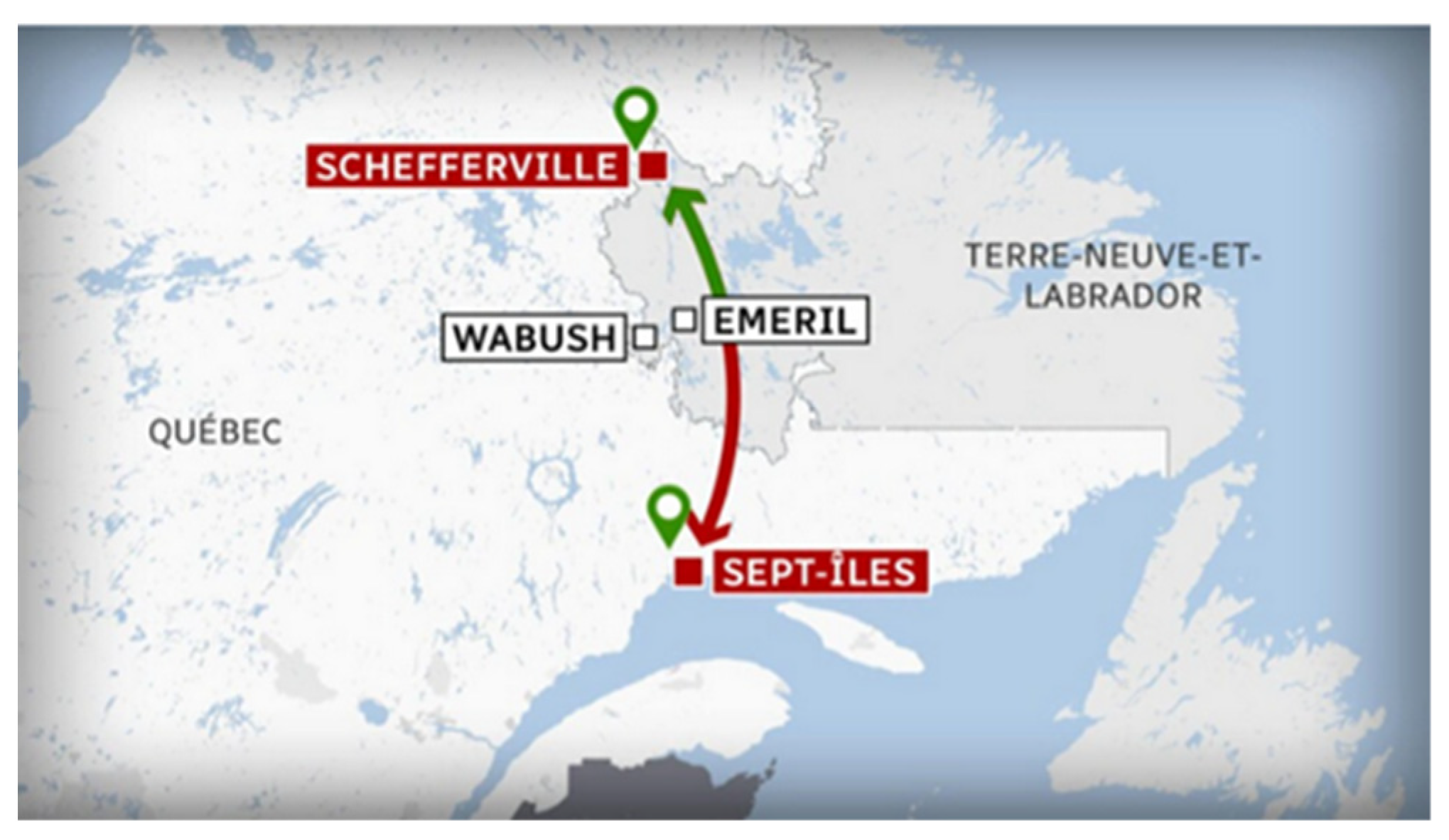
2. The Context of the Solution: The Isolated Environment
3. Selection of Suitable Radio Frequency Protocol
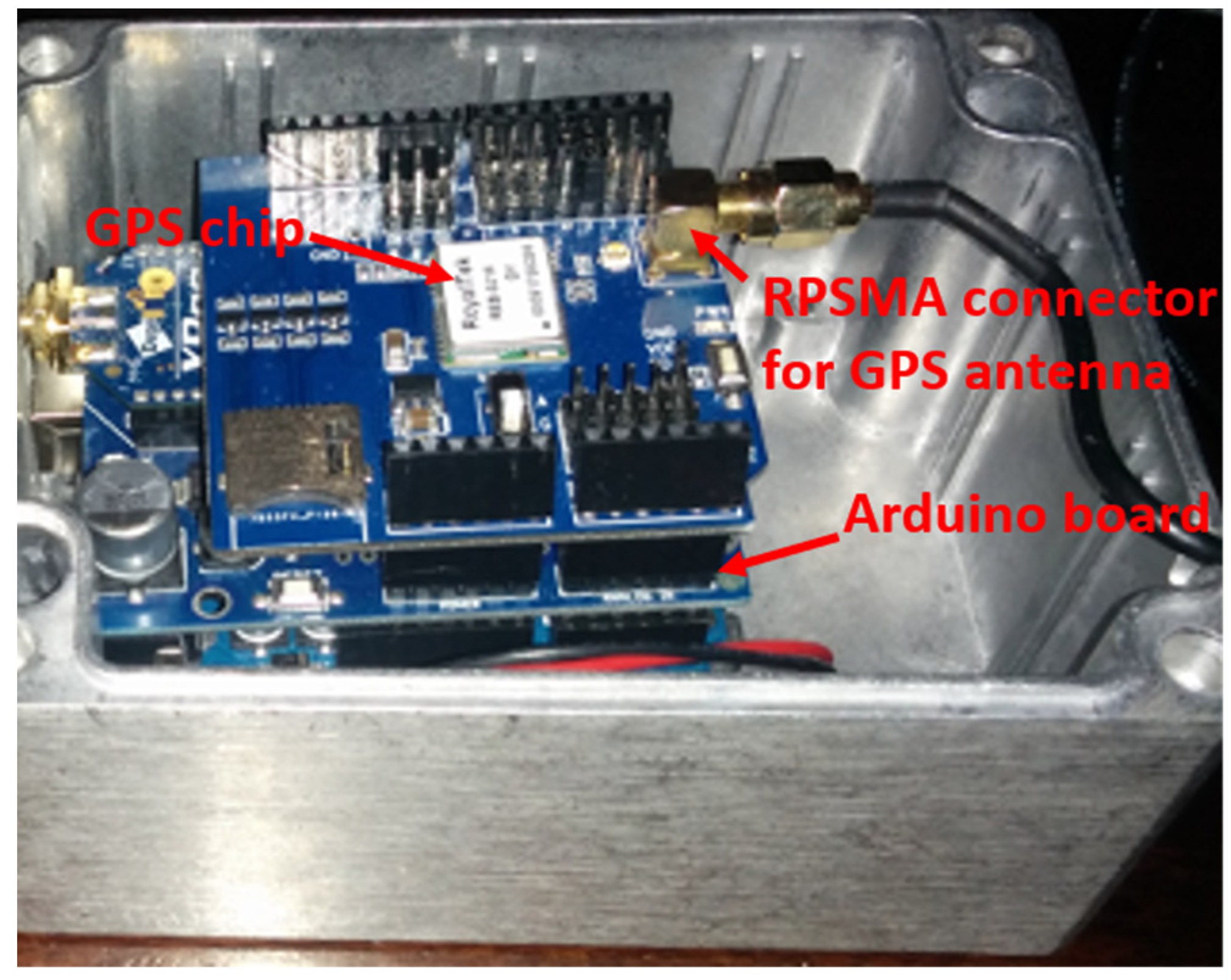
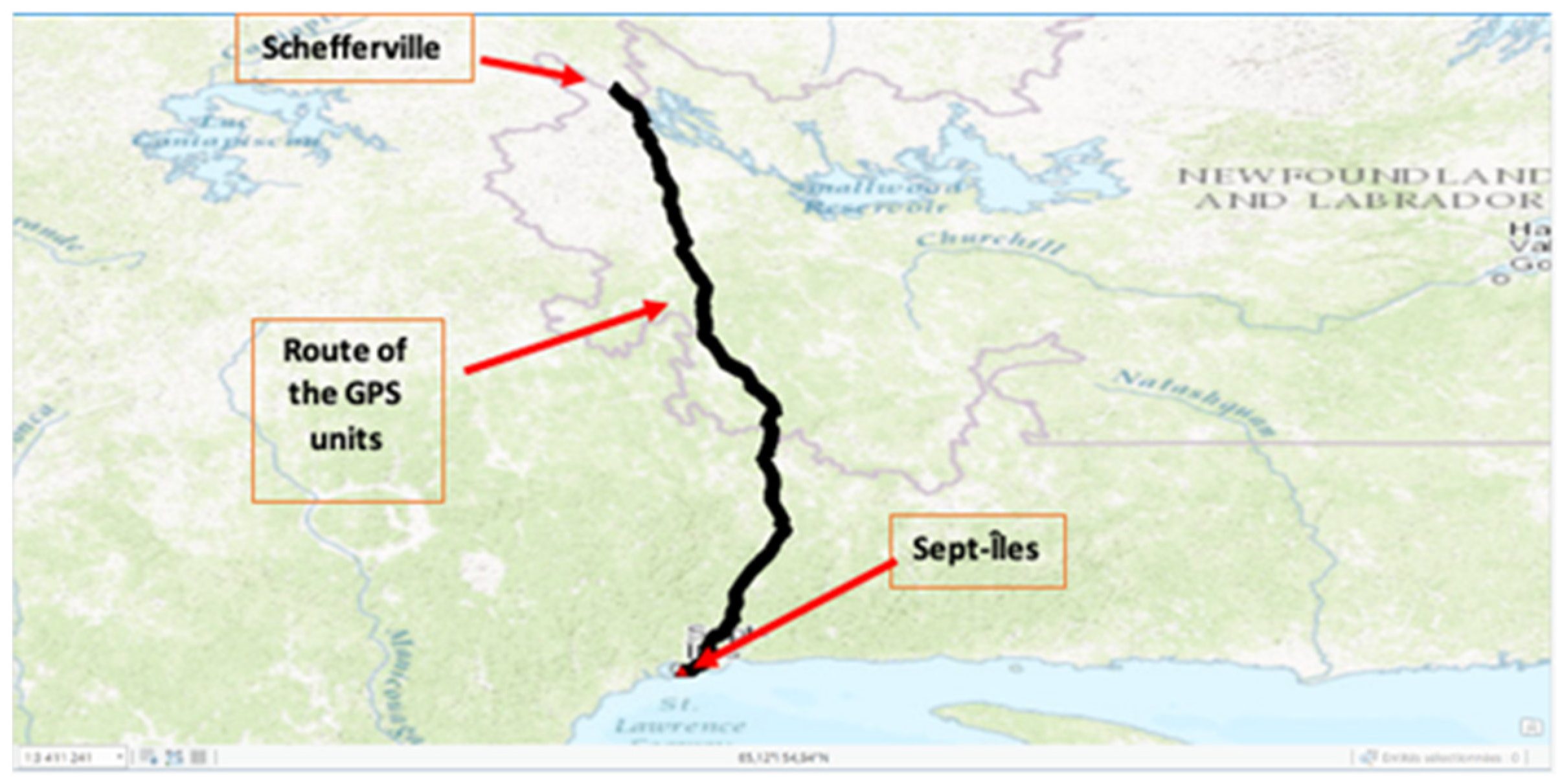
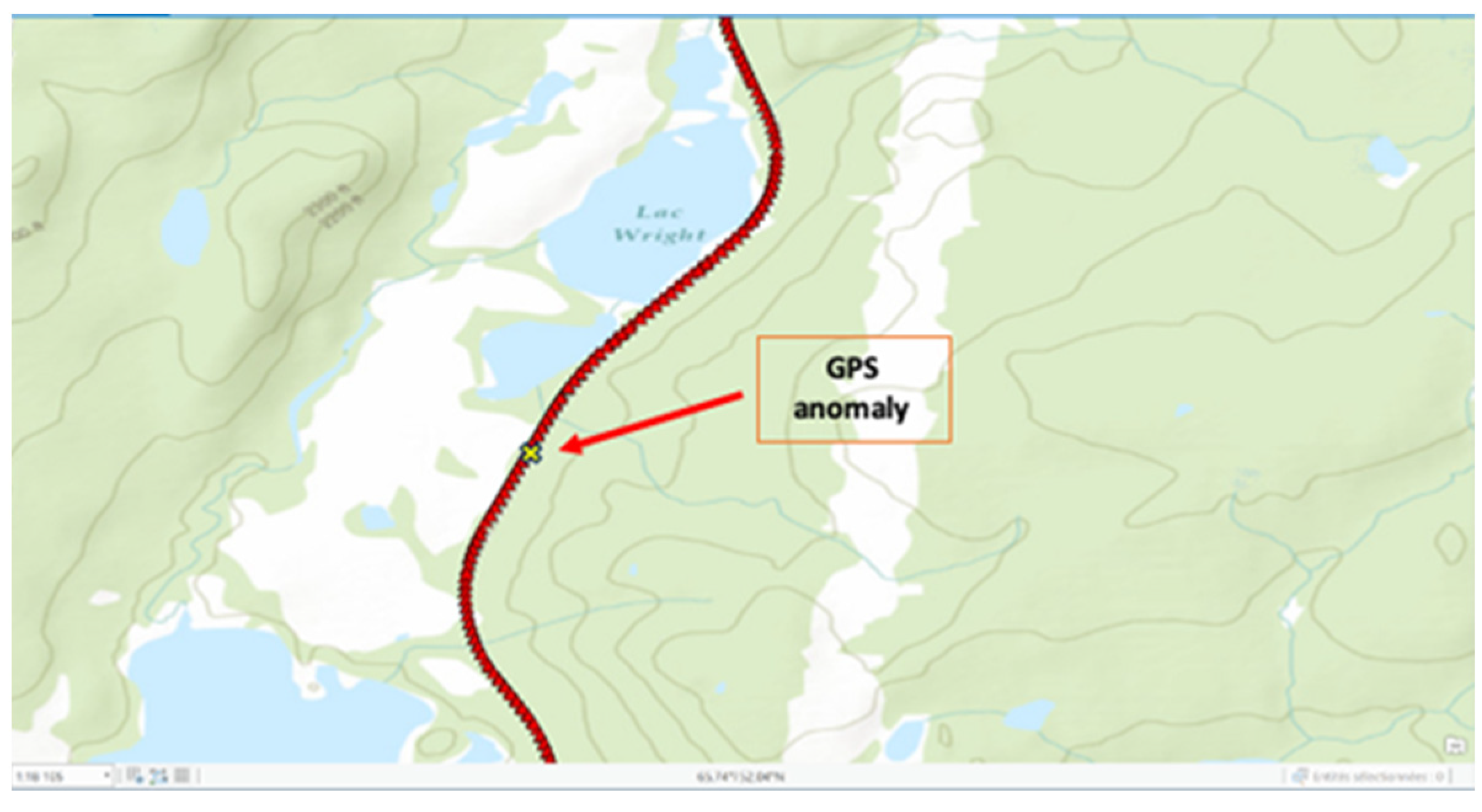
3.1. Global Positioning System (GPS) Coverage
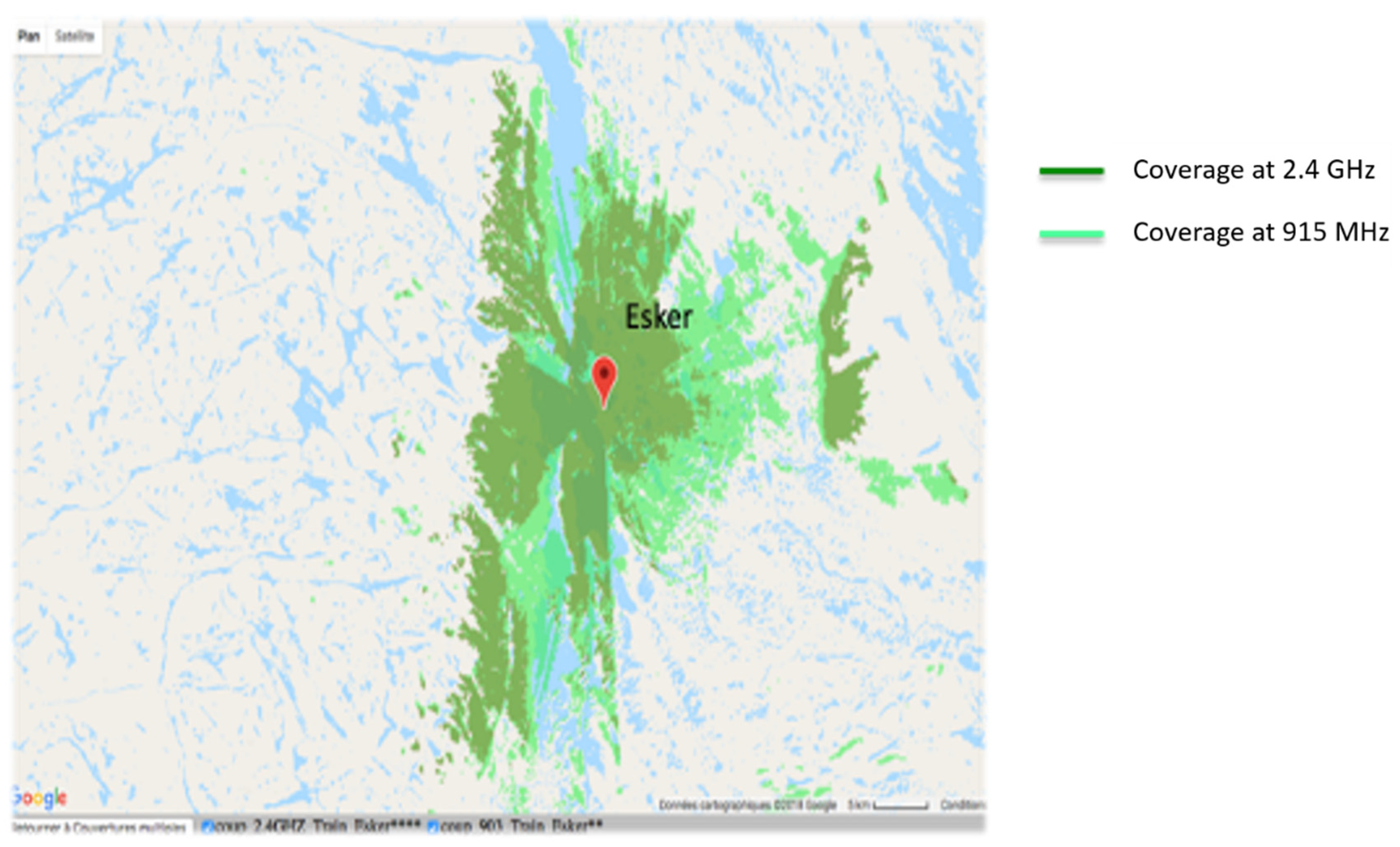
3.2. Choice of the Wireless Radio Protocol Solution
- -
- LoRa (with LoRaWAN network) or Sigfox;
- -
- LTE;
- -
- Wifi;
- -
- ZigBee;
- -
- Z-Wave;
- -
- Bluetooth;
- -
- Satellite.
4. System Model
4.1. Loss Path (LP) Model
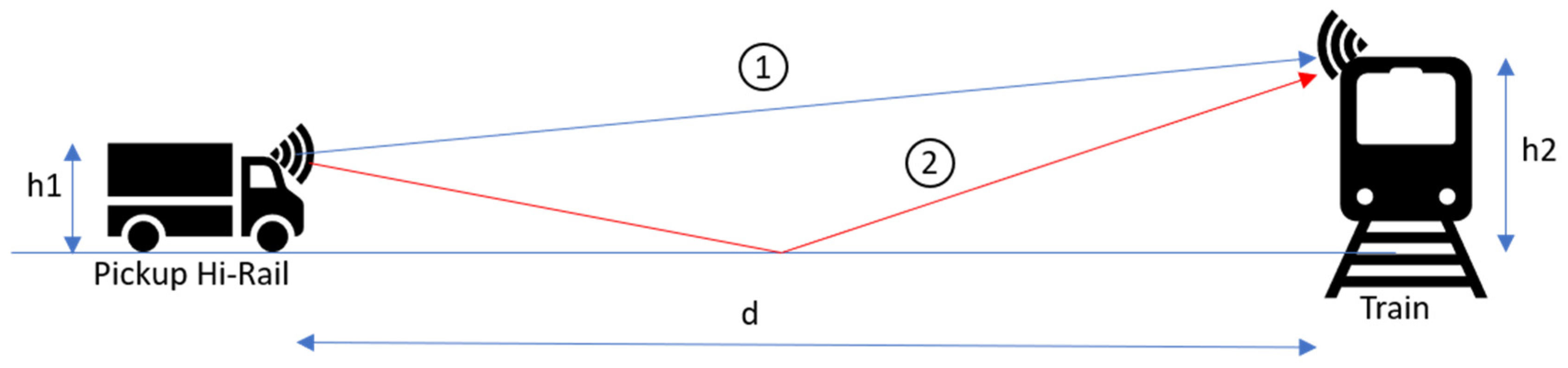
4.2. Loss Path Model with Ground Reflection
- Direct line;
- With a reflection on the ground.
4.3. Fading Model
4.3.1. Fading Due to Time Spread
4.3.2. Doppler Effect
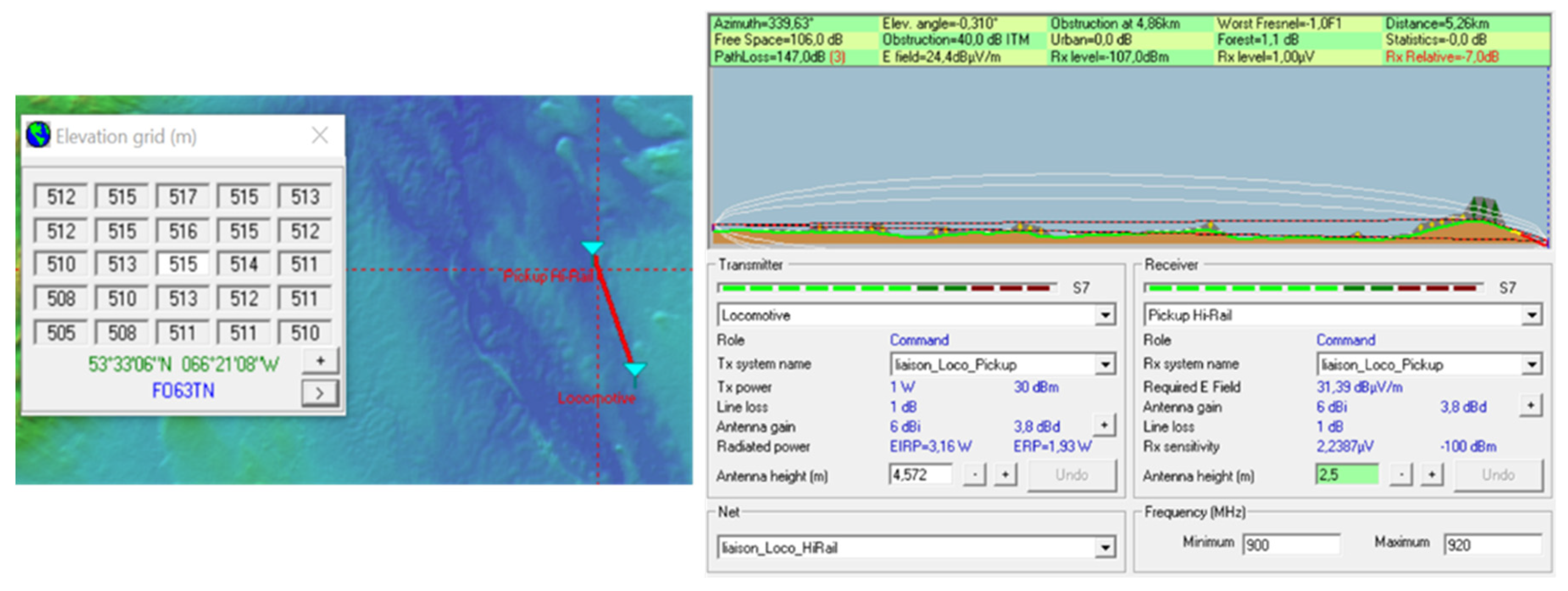
4.4. Irregular Terrain Model (ITM)
5. System Tests on Site
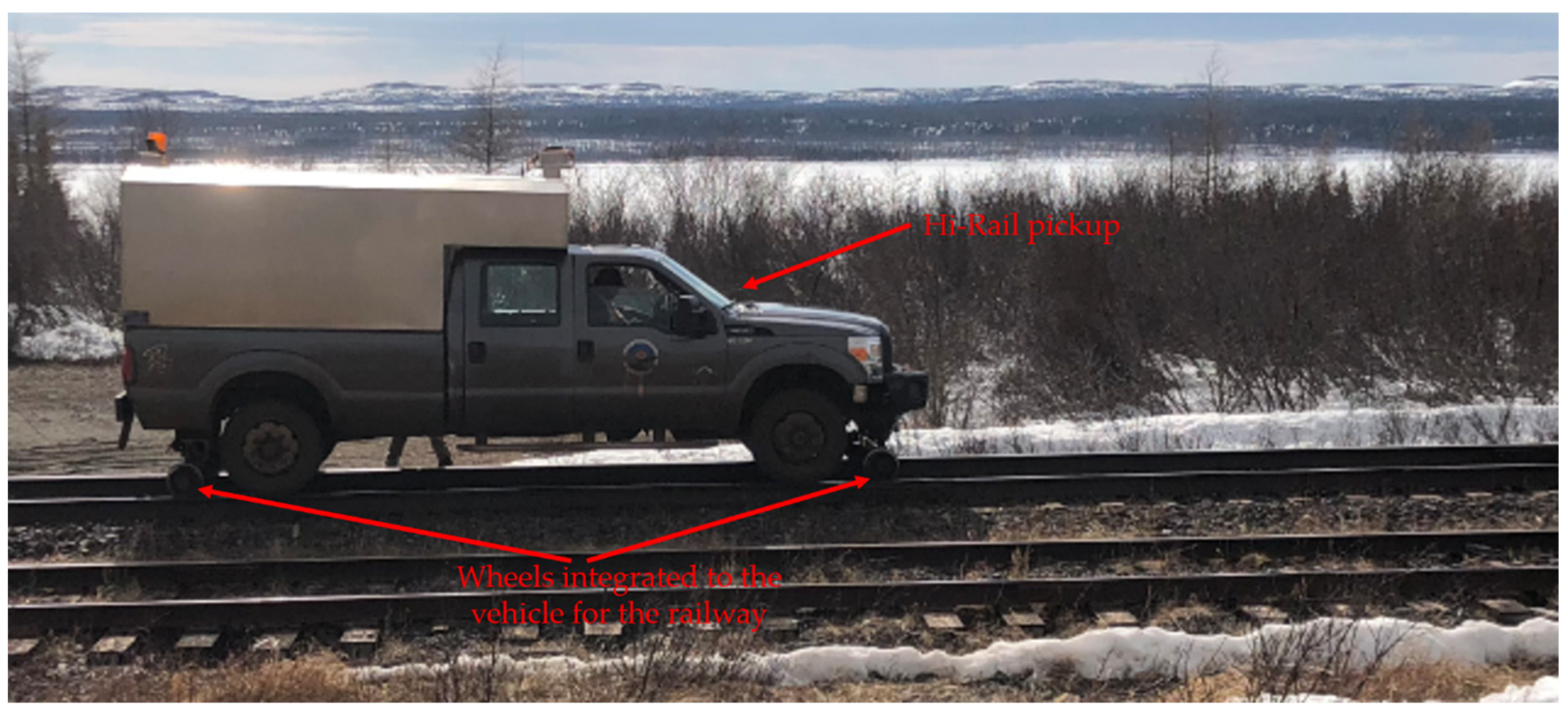
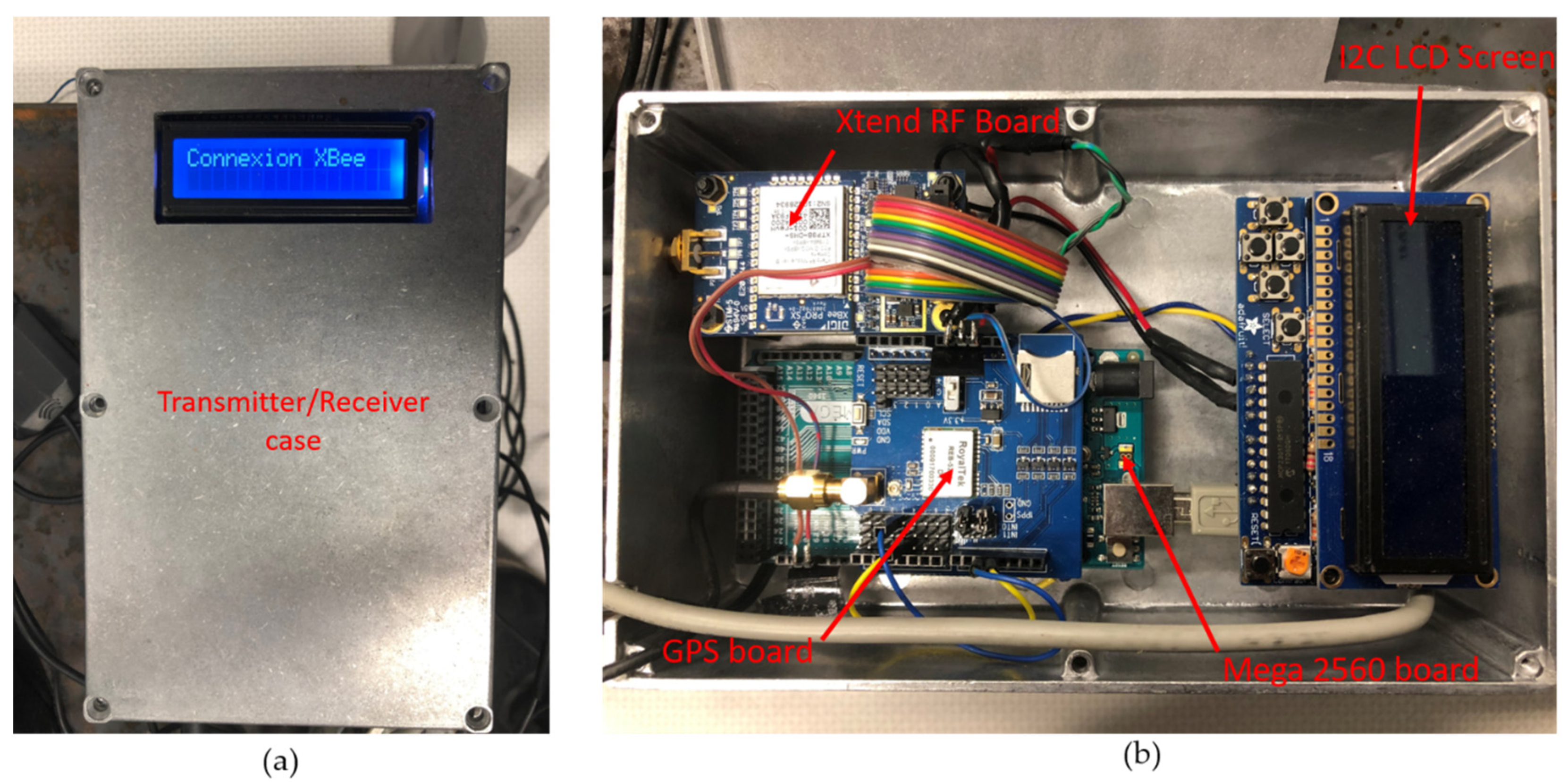
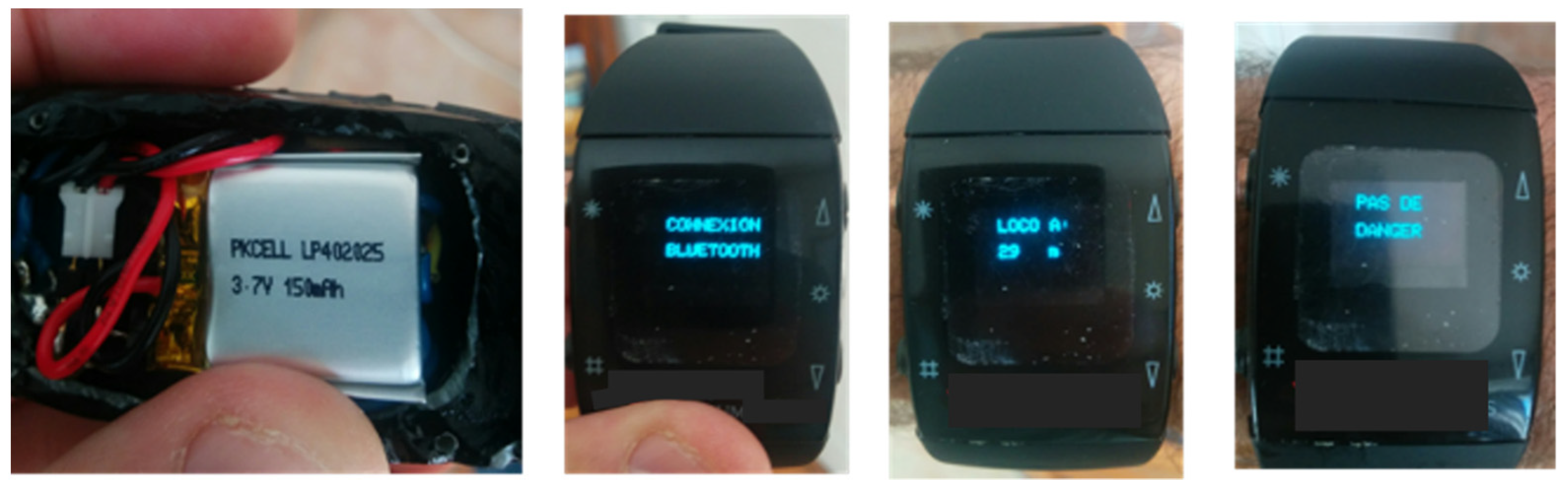
5.1. Design Decisions
- -
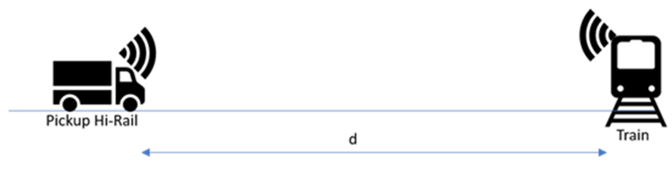
- Bluetooth connection: when the watch is switched on, it looks for pairing with the receiver in the Hi-Rail pickup;
- -
- No danger: meaning that the locomotive is outside a distance of 10 km;
- -
- The distance and a slowly tonality when the locomotive is located at a distance between 7 and 10 km;
- -
- The distance and a medium tonality when the locomotive is located at a distance between 3 and 7 km;
- -
- The distance and a very high-pitched sound when the locomotive is inside 3 km and also a flashing display.
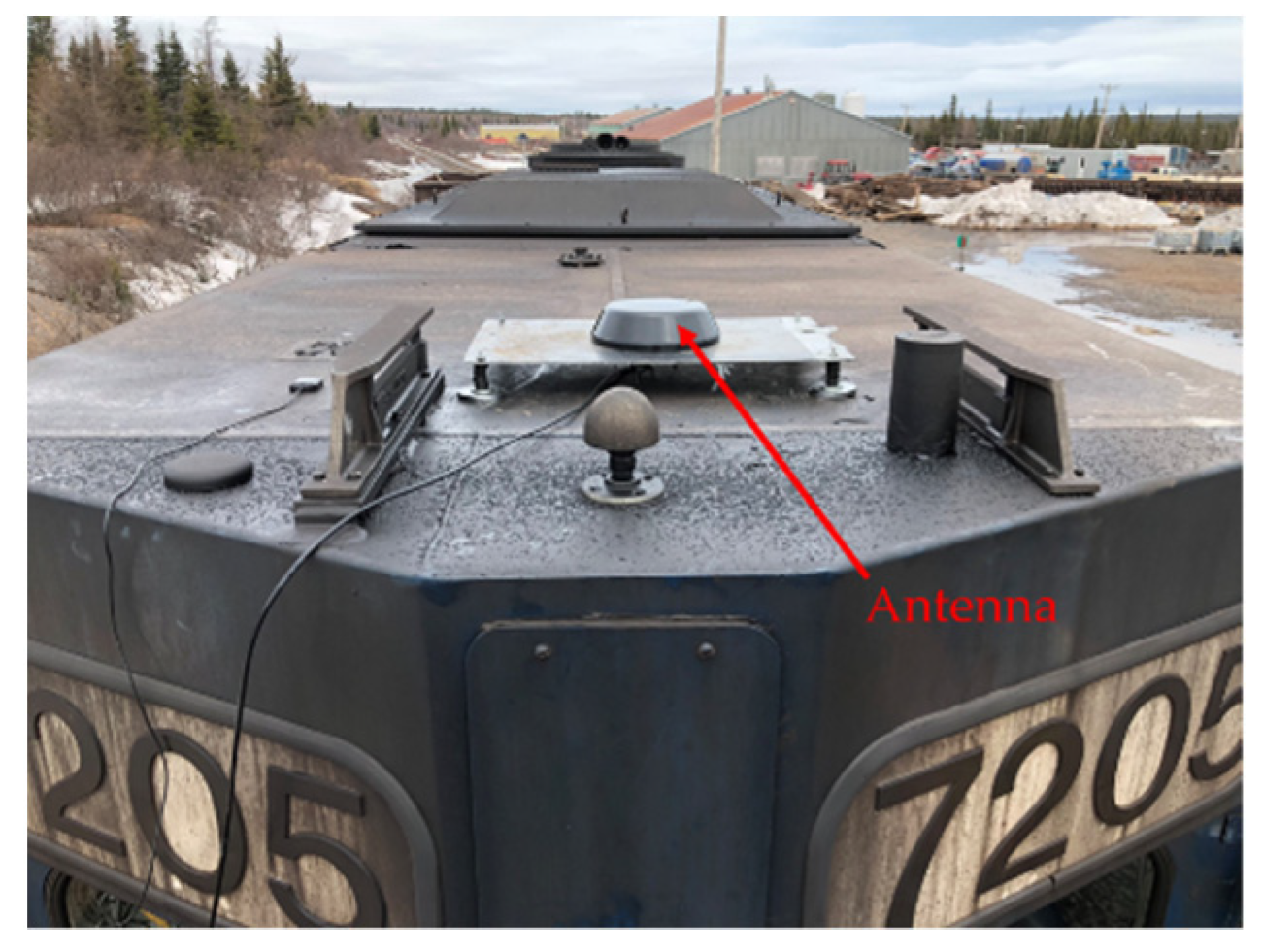
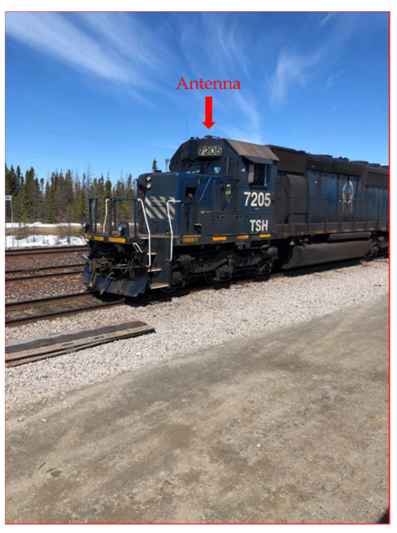
5.2. Railway Telecommunication System Test Procedure
5.3. Tests Results
6. Conclusions
Author Contributions
Funding
Institutional Review Board Statement
Informed Consent Statement
Data Availability Statement
Conflicts of Interest
References
- Bureau de la Sécurité des Transports du Canada. Available online: https://www.tsb.gc.ca/fra/index.html (accessed on 1 April 2021).
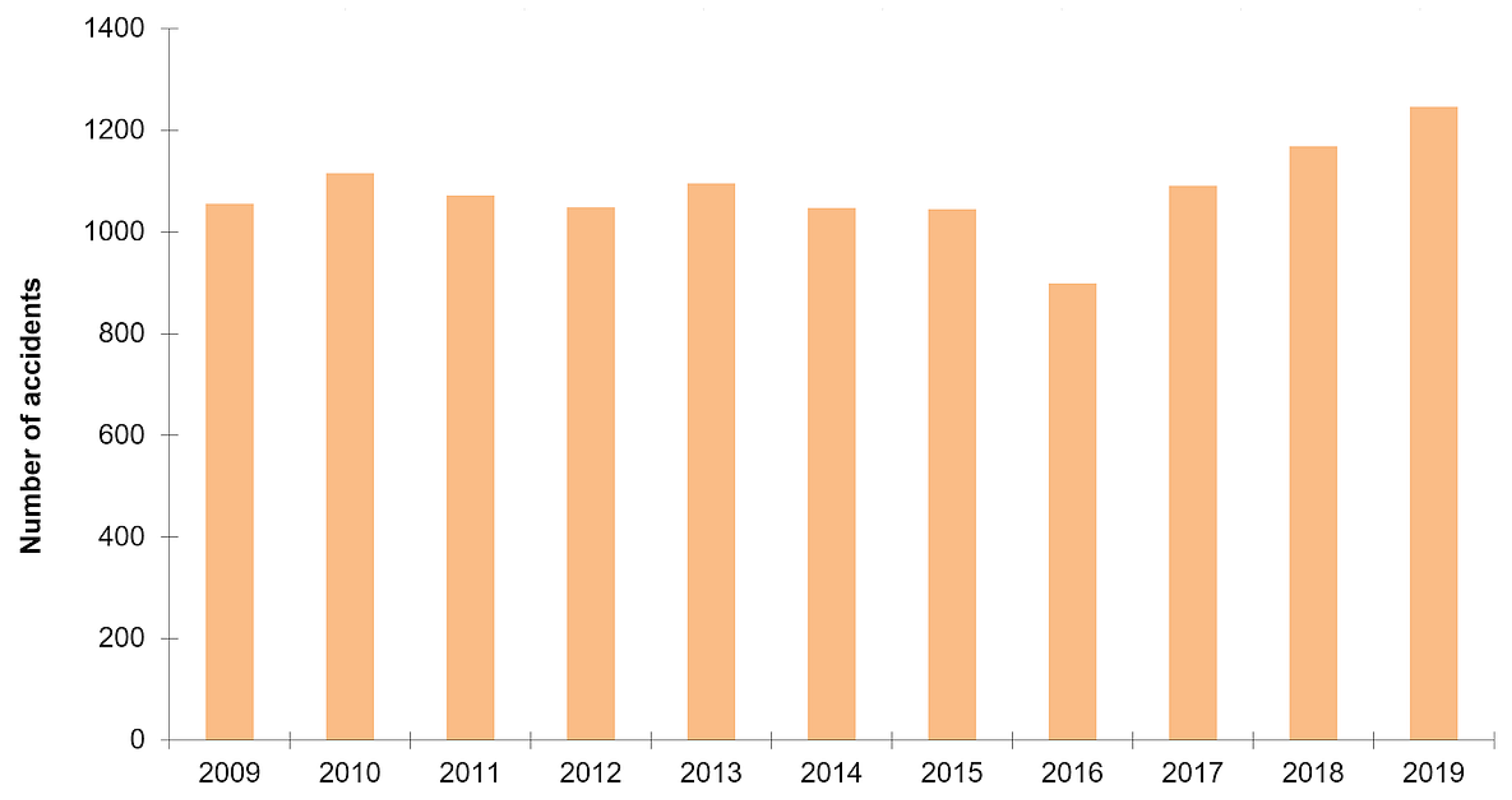
- Hausse de 42% des Accidents Ferroviaires Depuis 10 Ans. Radio-Canada, ICI Estrie. Available online: https://ici.radio-canada.ca/nouvelle/1718977/hausse-accidents-ferroviaires-canada (accessed on 11 July 2020).
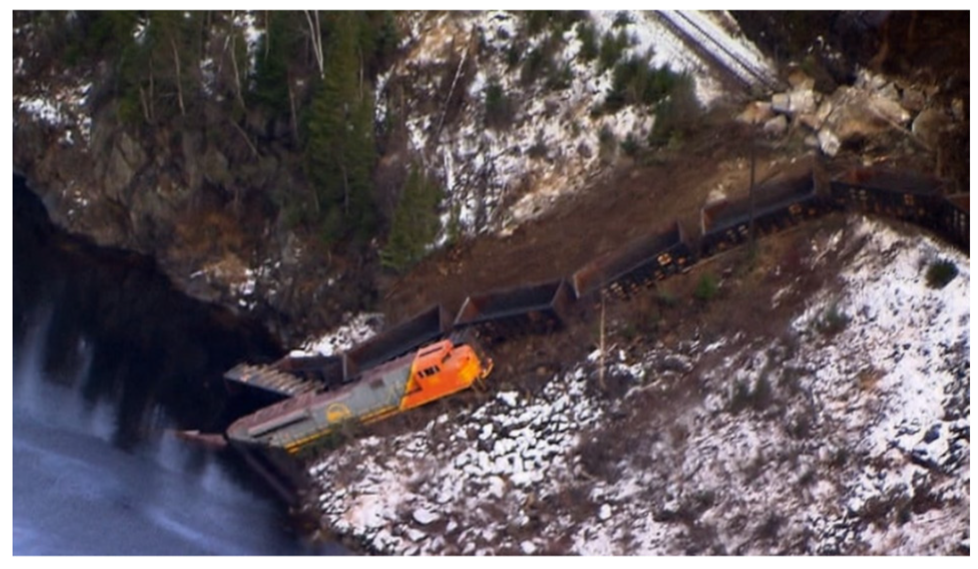
- Lac-Mégantic Rail Disater, Wikipedia. Update 15 August 2021. Available online: https://en.wikipedia.org/wiki/Lac-M%C3%A9gantic_rail_disaster (accessed on 23 December 2013).
- Railway Investigation Report R16H0024, Canadian Pacific Railway, Technical Report about Collision between Train and Track Unit. Available online: file:///C:/Users/ferl/Downloads/r16h0024.pdf (accessed on 6 March 2016).
- Ferré, G.; Giremus, A. LoRa Physical Layer Principle and Performance Analysis. In Proceedings of the IEEE International Conference on Electronics Circuits and Systems, Bordeaux, France, 9–12 December 2018. [Google Scholar]
- Lavric, A.; Petrariu, A.I.; Popa, V. Long Range SigFox Communication Protocol Scalability Analysis Under Large-Scale, High density Conditions. IEEE Access 2019, 7, 35816–35825. Available online: https://ieeexplore.ieee.org/stamp/stamp.jsp?arnumber=8660398 (accessed on 5 March 2019). [CrossRef]
- Phillips, C.; Sicker, D.; Grunwald, D. The Satbility of The Longley-Rice Irregular Terrain Model for Typical Problems, Technical Report CU-CS-1086-11, Department of Computer Science, University of Colorado. Available online: https://citeseerx.ist.psu.edu/viewdoc/download?doi=10.1.1.229.2362&rep=rep1&type=pdf (accessed on 8 September 2011).
- Farahani, S. Zigbee Wireless Networks AND Transceivers, 1st ed.; Collection Newnes Books Elsevier: Burlington, MA, USA, 2008; ISBN 9780750683937. [Google Scholar]
- Prasetyo, P.A.; Kitagawa, A. Quality of service and power consumption Optimization on the IEEE 802.15.4 Pulse Sensor Node based on Internet of Things. Instrum. J. Adv. Comput. Sci. Appl. 2019, 10, 144–154. [Google Scholar]
- Pozzar, D.M. Microwave and RF Design of Wireless Systems, 1st ed.; Wiley: Hoboken, NJ, USA, 2001; ISBN 9780471322825. [Google Scholar]
- Grenier, D. Antennes et Propagation Radio, Document, Département de Génie Informatique, Université Laval, Québec, Canada, Hiver 2020. Available online: http://w3.gel.ulaval.ca/~dgrenier/ap_notes-e.pdf (accessed on 15 January 2020).
- Phan, D.P. Contrôle de la Puissance Pour les Réseaux Sans Fil. Ph.D. Thesis, University of Poitier, Poitier, France, 2014. Available online: https://hal.archives-ouvertes.fr/tel-01095640v3/document (accessed on 11 February 2015).
- Paris, B.P. Modeling of Wireless Communication Using MATLAB, Dept Electrical and Comp. Engineering, George Mason University. 2010. Available online: https://its-wiki.no/images/5/5b/Mobility.pdf (accessed on 23 September 2009).
- Almashhadani, Y.S. Performance of M-ary FSK Modulation over AWGN and Rayleigh Fading Channels. J. Babylon Univ. Eng. Sci. 2017, 25, 1257–1266. [Google Scholar]
- Luengo, D.; Martino, L. Statistical Simulation of Multipath Fading Channels for Mobile Wireless Digital Communication Systems. In Chapter in Book Simulation Technologies in Networking and Communications: Selecting the Best Tool for the Test; CRC Press; Taylor & Francis Group: Boca Raton, FL, USA, 2014; Available online: https://www.researchgate.net/publication/298989533_Statistical_Simulation_of_Multipath_Fading_Channels_for_Mobile_Wireless_Digital_Communication_Systems (accessed on 15 December 2014). [CrossRef]
- Lemoine, C.; Amador, E.; Besnier, P. On the K-Factor for Rician Chanel Simulated in Reverberation Chamber. IEEE Trans. Antennas Propag. 2010, 59, 1003–1012. Available online: https://www.researchgate.net/publication/224208499_On_the_KFactor_Estimation_for_Rician_Channel_Simulated_in_Reverberation_Chamber (accessed on 30 December 2010). [CrossRef]
- MATLAB. Rayleigh Modelisation. Available online: https://www.mathworks.com/help/comm/ug/fading-channels.html#bq5zk36 (accessed on 15 March 2021).
- Iskander, C. A MATLAB Based Object Oriented Approach to Multipath Fading Channel. Available online: https://www.mathworks.com/matlabcentral/fileexchange/18869-a-matlab-based-object-oriented-approach-to-multipath-fading-channel-simulation (accessed on 15 May 2016).
- Willis, S.L. Investigation into Long-Range Wireless Sensor Networks. Ph.D. Thesis, James Cook University, Townsville, Australia, 2007. [Google Scholar]
- Xia, H.; Alshatari, K.; Lawrence, V.B.; Yao, Y.D.; Montalvo, A. Cellular Signal Identification Using Convolutional Neural Networks: AWGN and Rayleigh Fading Channels. In Proceedings of the IEEE International Symposium on Dynamic Spectrum Access Network (DySPAN), Newark, NJ, USA, 11–14 November 2019. [Google Scholar]
- Gorantla, K.; Mani, V. Simulink model for Zigbee transceiver using OQPSK modulation under fading channels. In Proceedings of the International Conference on Communications and Signal Processing (ICCSP), Melmaruvathur, India, 2–4 April 2015. [Google Scholar]
- Chehri, H. Étude et Caractérisation d’un Canal de Propagation Pour Les Réseaux VANET. Master’s Thesis, Université du Québec en Abitibi-Témiscamingue, Rouyn-Noranda, QC, Canada, 2014. [Google Scholar]
- Pagani, P. Caractérisation et Modélisation du Canal de Propagation Radio en Contexte Ultra Large Bande. Ph.D. Thesis, INSA (Institut National des Sciences Appliquées), Rennes, France, 2005. [Google Scholar]
- Kasampalis, S.; Lazaridis, P.; Zaharis, D.Z.; Bizopoulos, A.; Zettas, S.; Cosmas, J. Comparison of Longley-Rice, ITU-R P.1546 and Hata-Davidson Propagation Models for DVB-T Coverage Prediction. In Proceedings of the IEEE International Symposium on Broadband Multimedia Systems and Broadcasting, Beijing, China, 25–27 June 2014; Available online: https://www.researchgate.net/publication/264003637_Comparison_of_Longley-Rice_ITU-R_P1546_and_Hata-Davidson_propagation_models_for_DVB-T_coverage_prediction (accessed on 11 August 2014).


| Technology | Frequency (MHz) | Range | Rate | Operating Conditions | Suitable for Isolated Environment with High Range |
|---|---|---|---|---|---|
| LoRa | 915 | 25 km | [290 bps; 50 kps] | Internet Connection Needed | No |
| XBee UHF | 915 | 64 km | 50–250 kbps | No Condition | YES |
| XBee | 2400 | 100 m | 50–250 kbps | No Condition | No |
| LTE | 700; 850 1700/2100 2600 | <30 km per cell | <75 Mbps (uplink) <300 Mbps | LTE Base Stations Needed | No |
| Bluetooth | 2400 | 20 m | 54 Mbps (BLE 5) | No Condition | No |
| Z-Wave | 915 | 400 m | 100 kbps | No Condition | No |
| Wifi 1 | 2400 | 90 m | [450 Mbps; 600 Mbps] | No Condition | No |
| Wifi 2 | 5000 | 30 m | <1.35 Gbps | No Condition | No |
| Results | Modelizations and Simulations | On Site (Railway Track) | Wishes of the Railway Company |
|---|---|---|---|
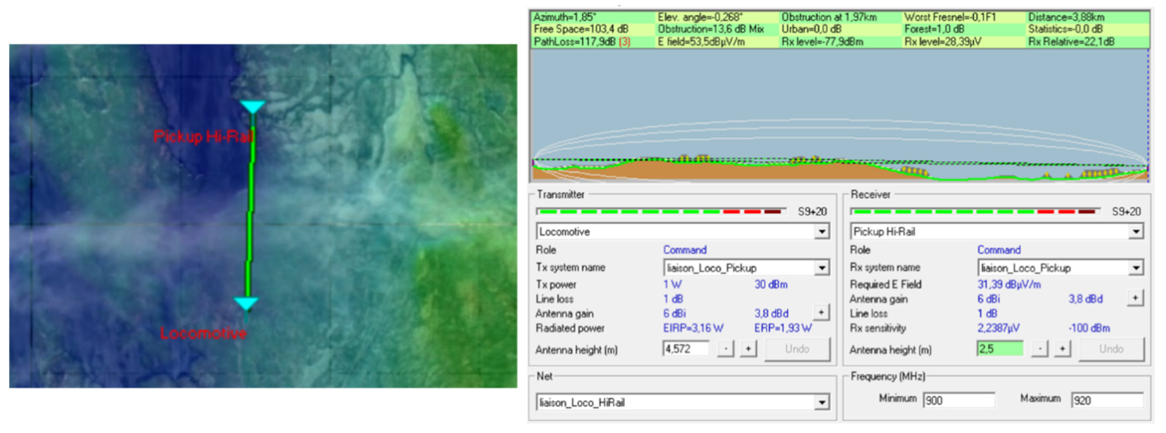
| Mean Range | 3.5 km | 3 km | 2 km |
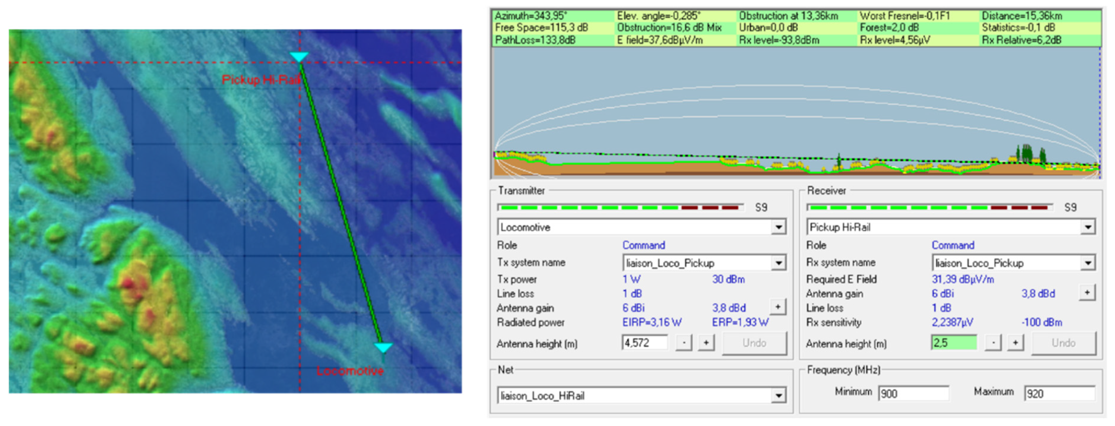
| Maximum Range | 15.36 km | 10 km | 3 km |
Publisher’s Note: MDPI stays neutral with regard to jurisdictional claims in published maps and institutional affiliations. |
© 2021 by the authors. Licensee MDPI, Basel, Switzerland. This article is an open access article distributed under the terms and conditions of the Creative Commons Attribution (CC BY) license (https://creativecommons.org/licenses/by/4.0/).
Share and Cite
Ferrier, L.; Ibrahim, H.; Issa, M.; Ilinca, A. Development and Validation of a Railway Safety System for Nordic Trains in Isolated Territories of Northern Quebec Based on IEEE 802.15.4 Protocol. Sensors 2021, 21, 6129. https://doi.org/10.3390/s21186129
Ferrier L, Ibrahim H, Issa M, Ilinca A. Development and Validation of a Railway Safety System for Nordic Trains in Isolated Territories of Northern Quebec Based on IEEE 802.15.4 Protocol. Sensors. 2021; 21(18):6129. https://doi.org/10.3390/s21186129
Chicago/Turabian StyleFerrier, Laurent, Hussein Ibrahim, Mohamad Issa, and Adrian Ilinca. 2021. "Development and Validation of a Railway Safety System for Nordic Trains in Isolated Territories of Northern Quebec Based on IEEE 802.15.4 Protocol" Sensors 21, no. 18: 6129. https://doi.org/10.3390/s21186129
APA StyleFerrier, L., Ibrahim, H., Issa, M., & Ilinca, A. (2021). Development and Validation of a Railway Safety System for Nordic Trains in Isolated Territories of Northern Quebec Based on IEEE 802.15.4 Protocol. Sensors, 21(18), 6129. https://doi.org/10.3390/s21186129