
Design of a Reconfigurable Wall Disinfection Robot

 , , ,
, , ,  and
and
Abstract
:1. Introduction
1.1. Background
1.2. Existing Technologies
1.2.1. Disinfection Methods and Mechanism
1.2.2. Wall Following Methods
1.2.3. Reconfigurable Robotics
1.3. Aims and Contributions
2. Robot Platform
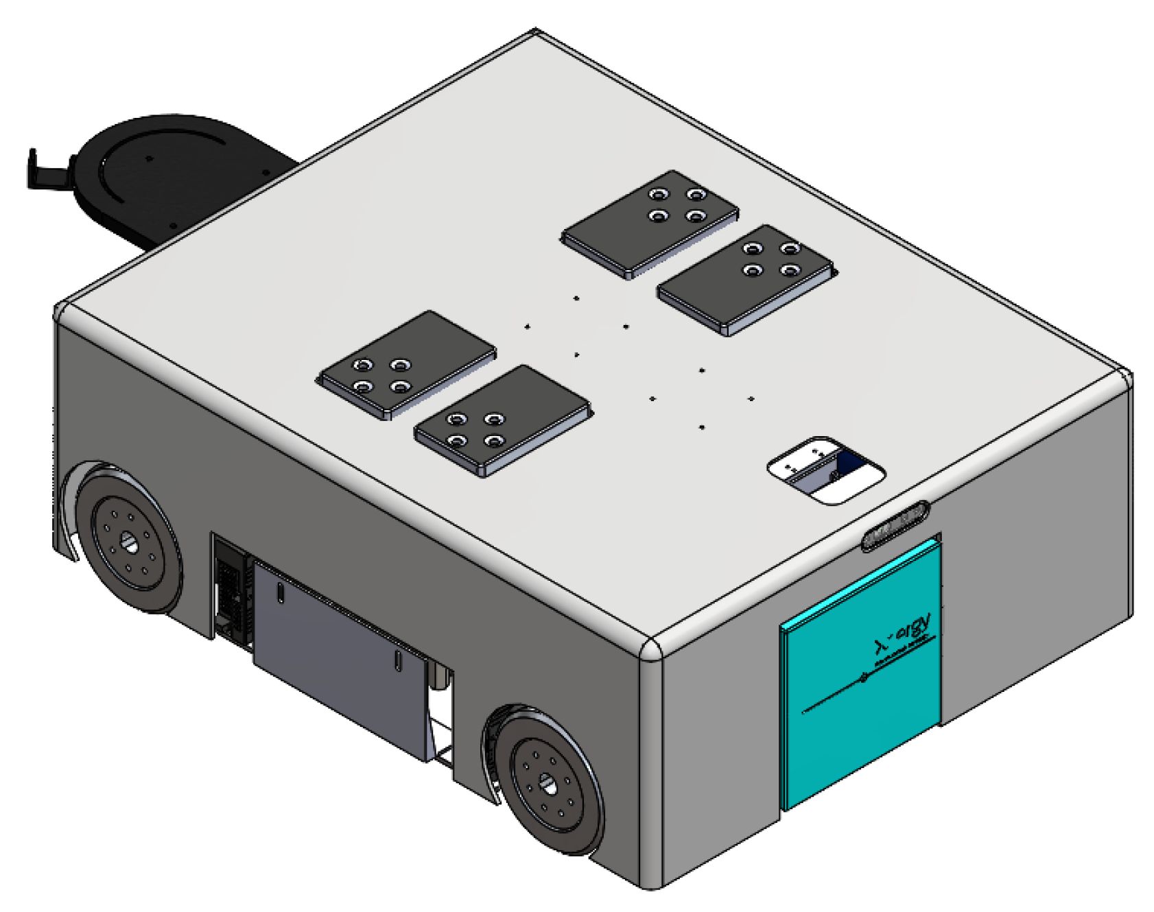
2.1. Overview
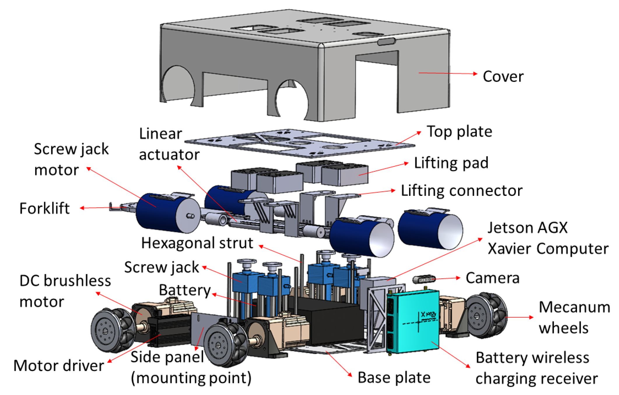
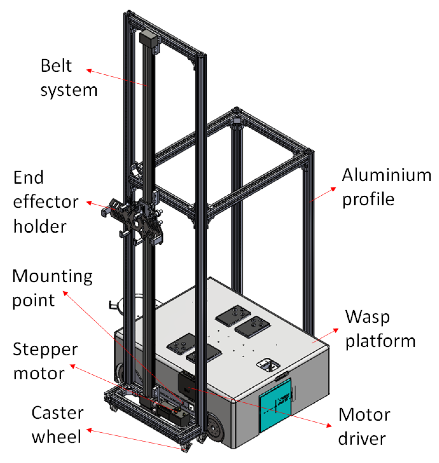
2.2. Mechanical Design
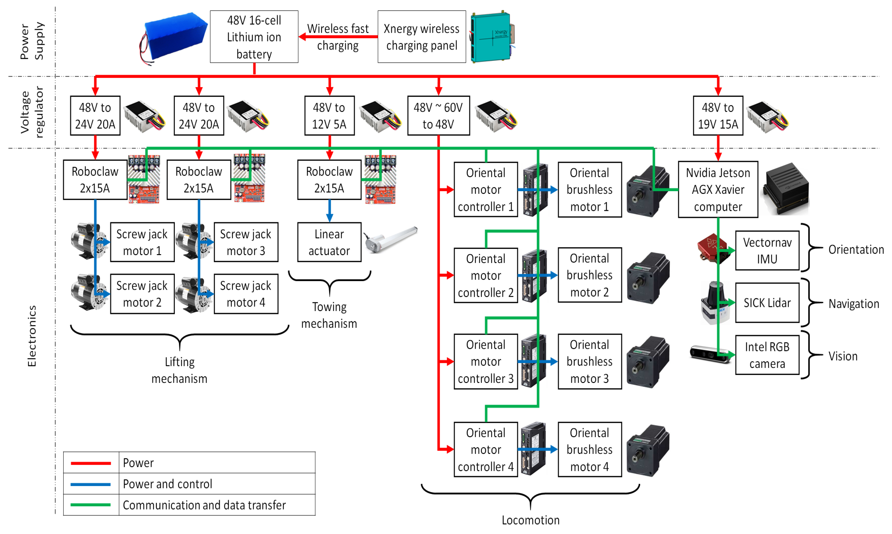
2.3. Power System and Electronics
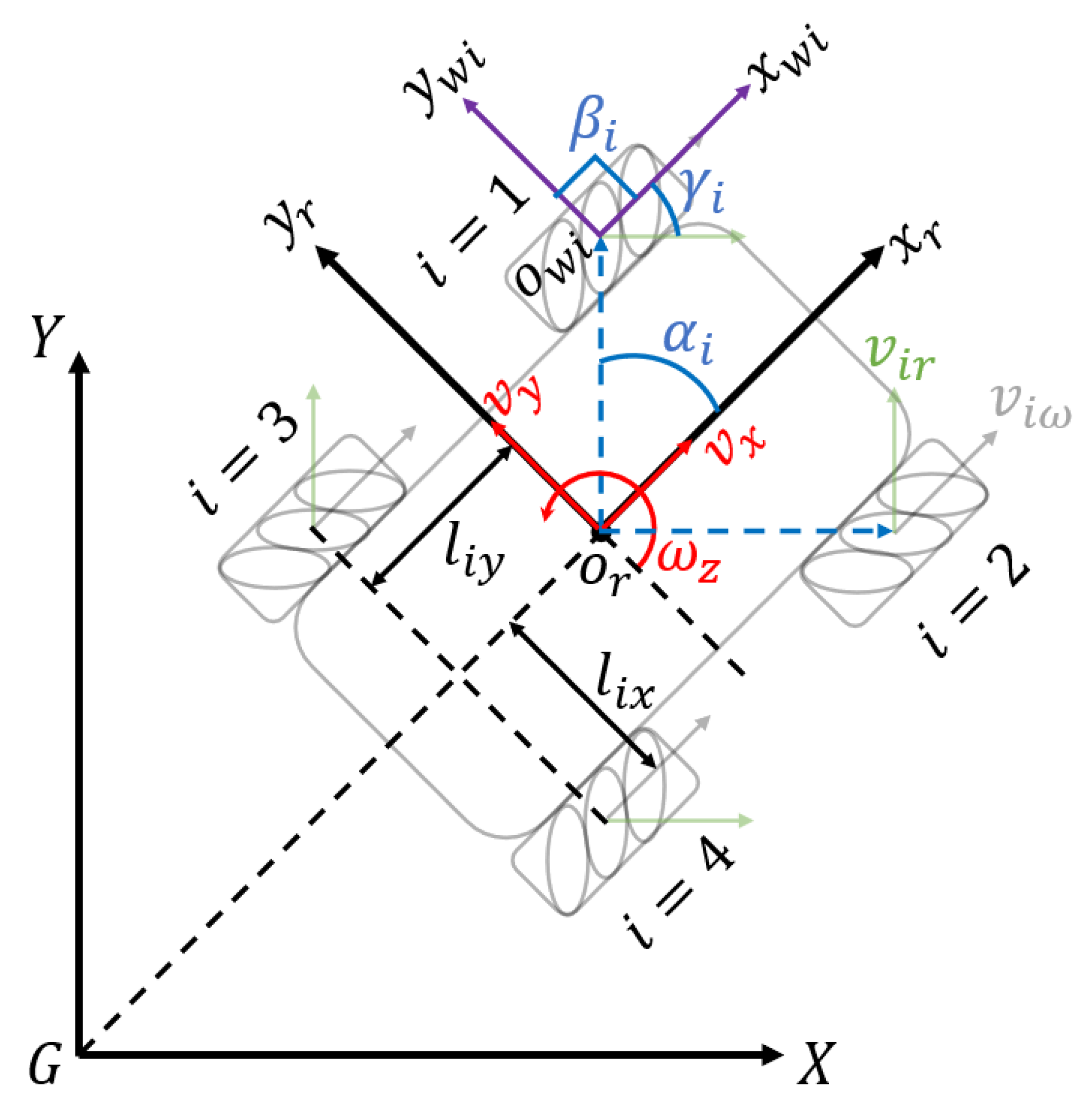
2.4. Kinematics Modeling
- X, G, Y: The inertial frame.
- : The Wasp platform base frame. is the center of robot base.
- : The coordinate system of ith wheel. is the wheel center point.
- : The angle between and .
- : The angel between and .
- : The angle between and .
- : The velocity of passive rollers in ith wheel.
- : The velocity of ith wheel correspond to wheel revolution.
- : Half the distance between front wheels or rear wheels.
- : Half the distance between front wheel and rear wheel.
- : Longitudinal velocity of Wasp platform.
- : Transversal velocity of Wasp platform.
- : Angular velocity of Wasp platform.

3. Wall-Following Method
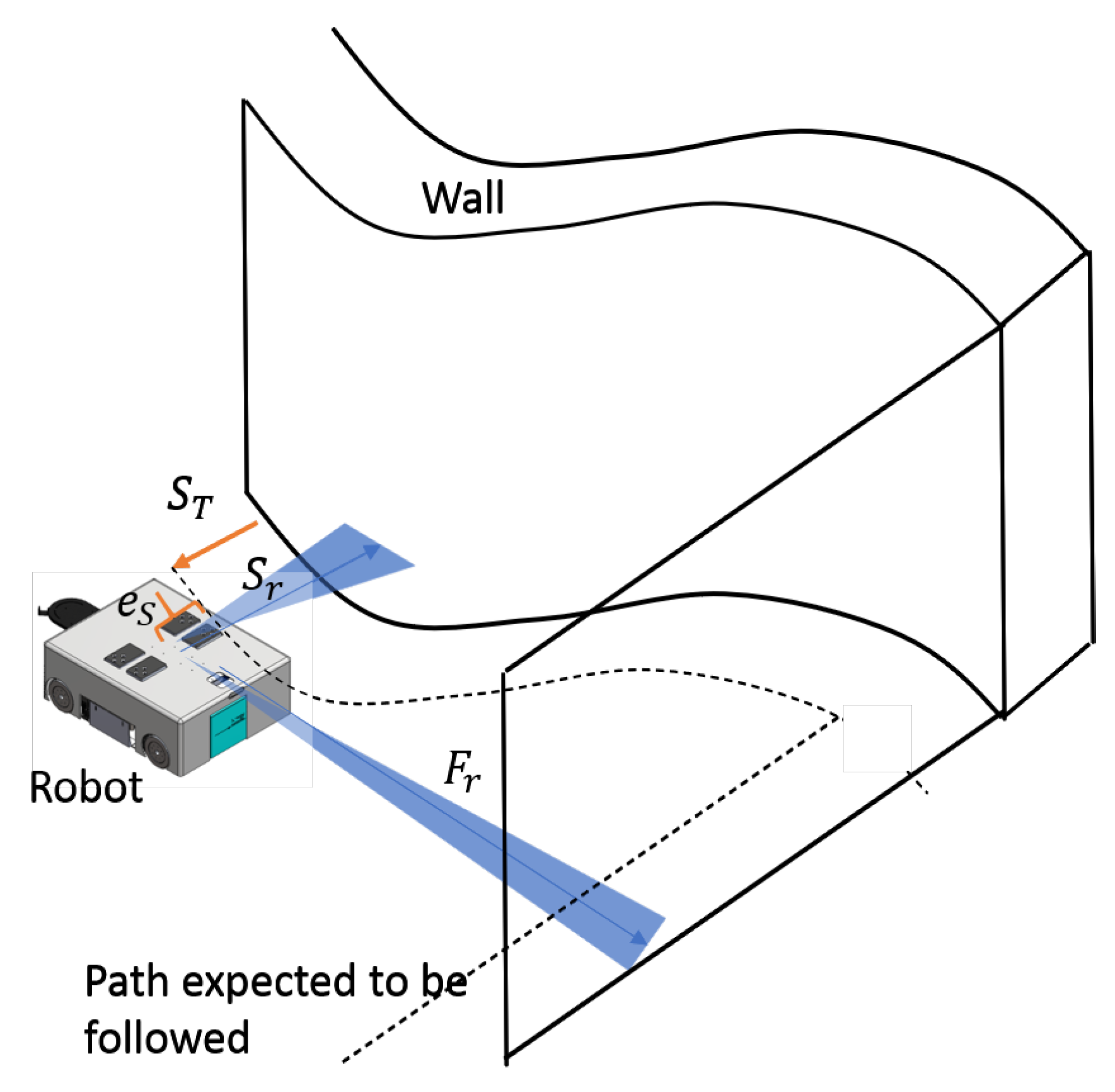
3.1. Overview
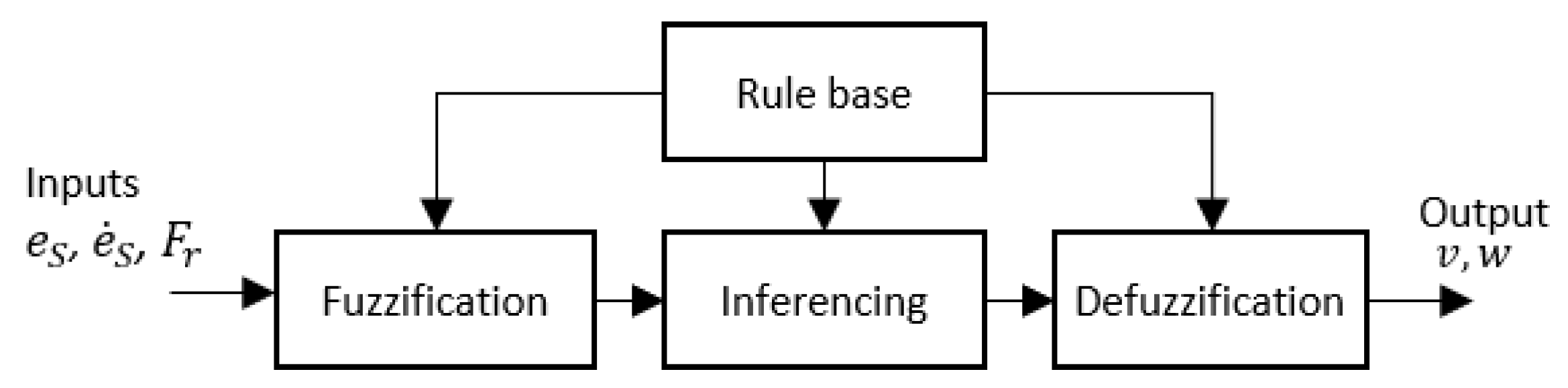
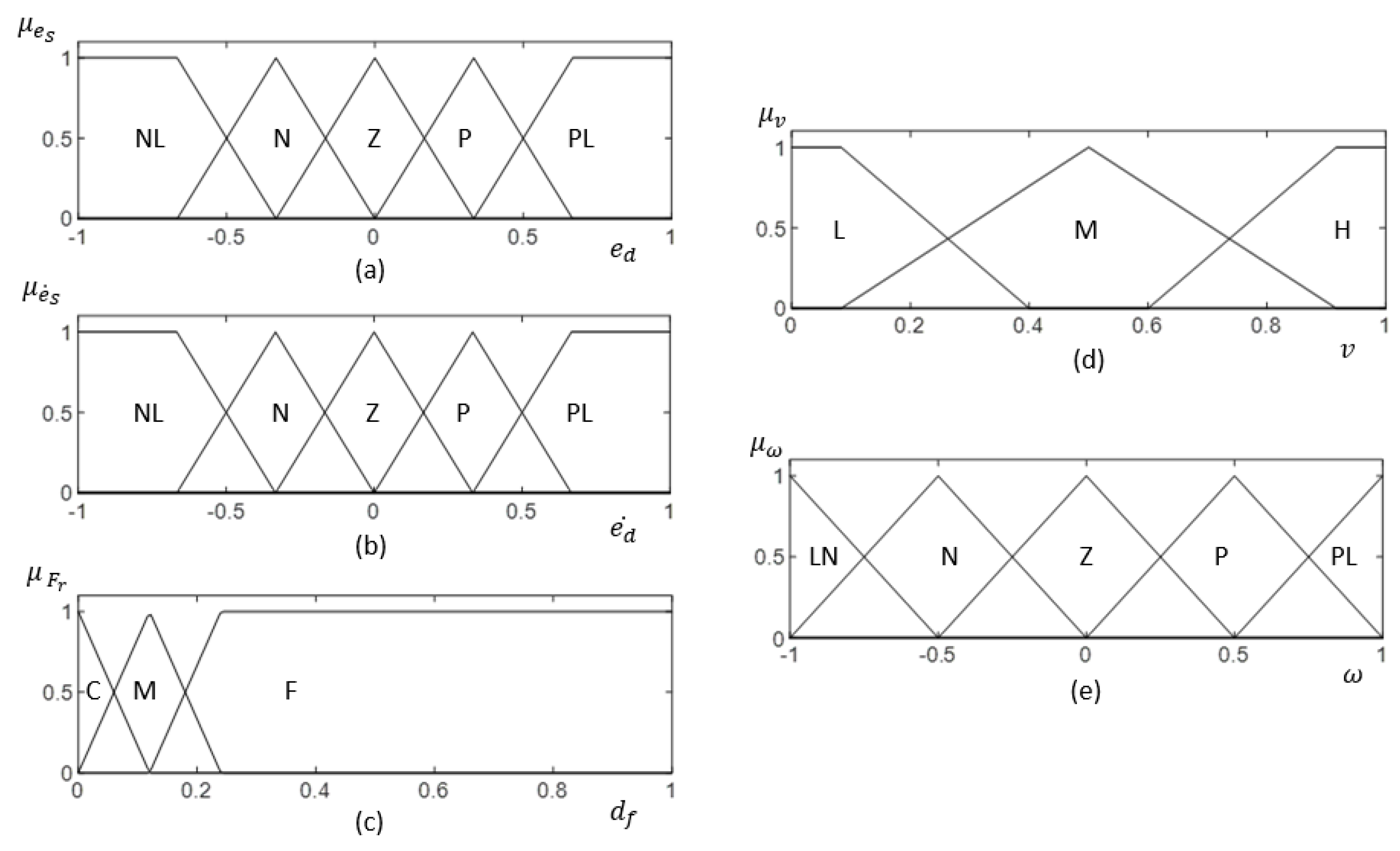
3.2. Fuzzy Logic System (FLS)
4. Results and Discussion
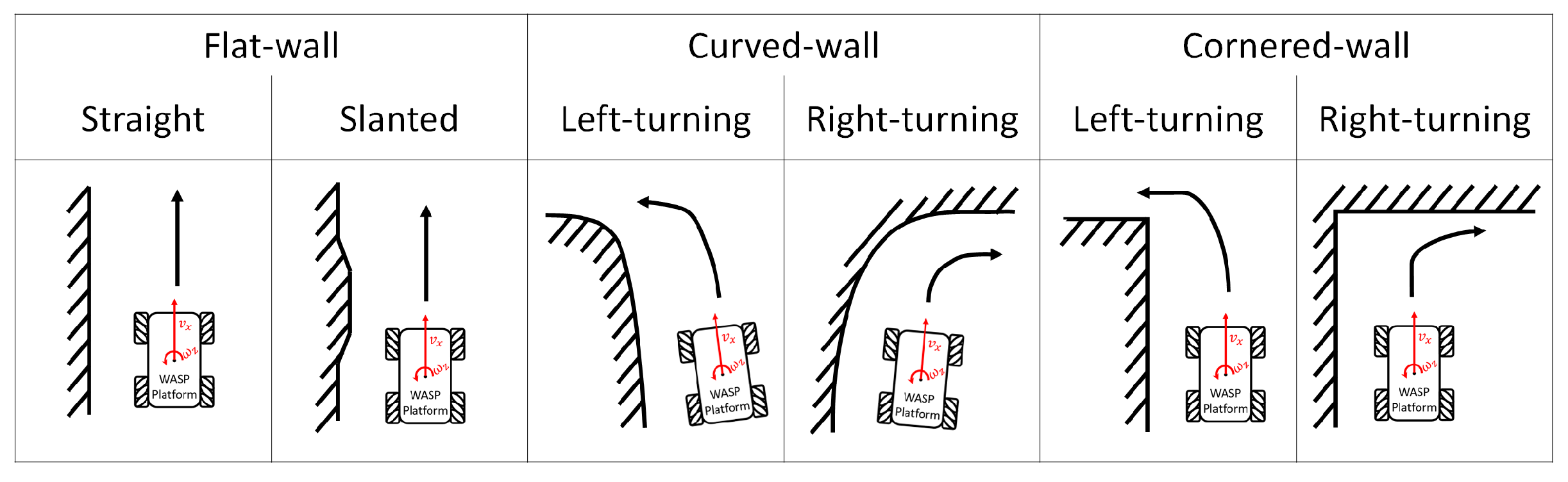
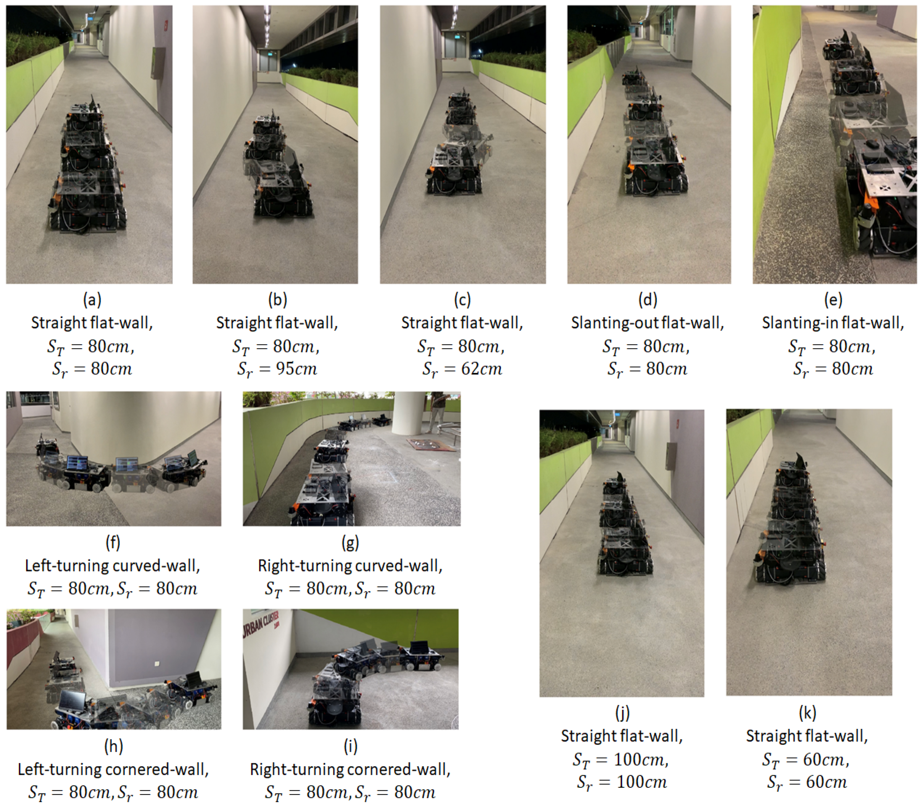
4.1. Experiment Setup
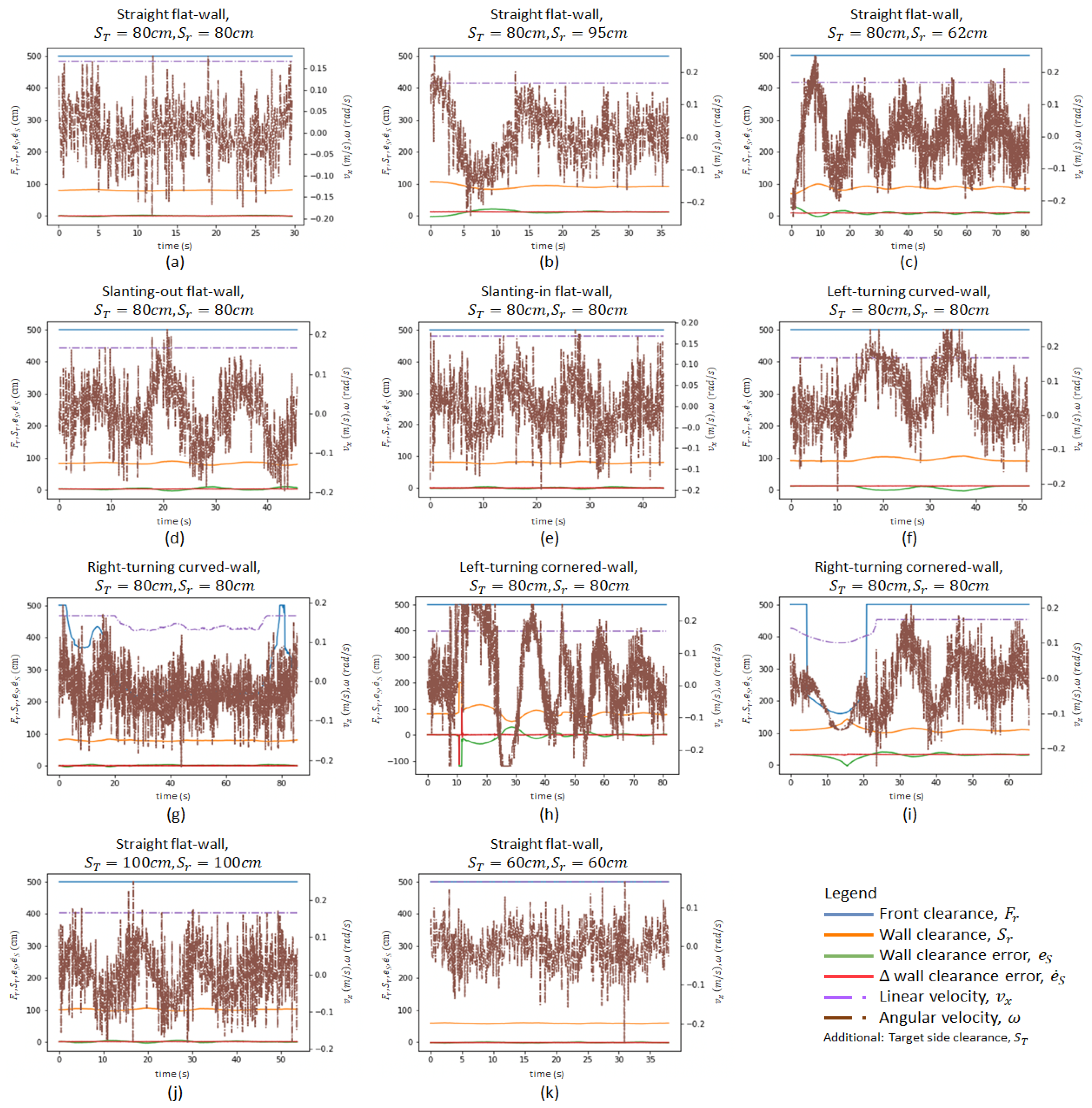
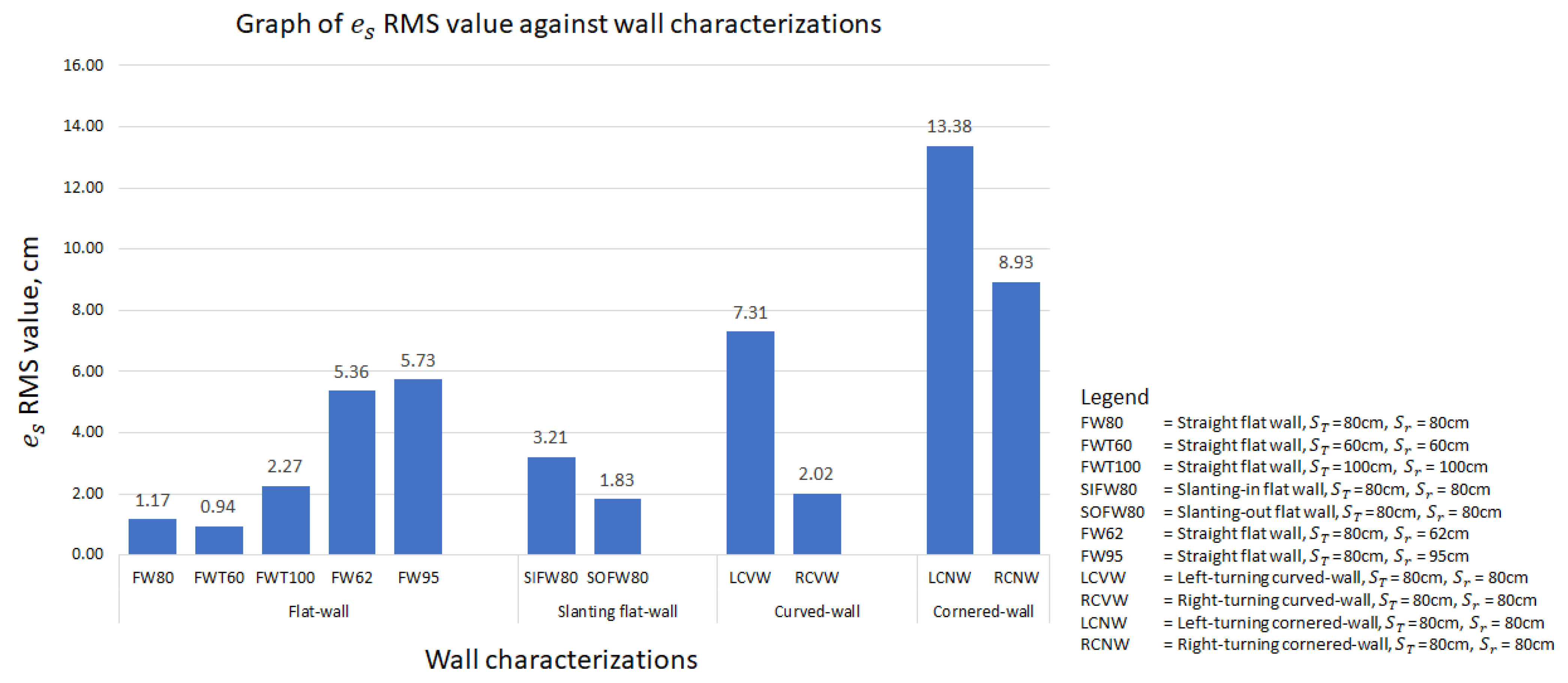
4.2. Results Analysis
4.3. Discussion
5. Conclusions
Supplementary Materials
Author Contributions
Funding
Conflicts of Interest
References
- Lotfi, M.; Hamblin, M.R.; Rezaei, N. COVID-19: Transmission, prevention, and potential therapeutic opportunities. Clin. Chim. Acta 2020, 508, 254–266. [Google Scholar] [CrossRef]
- Maurya, D.; Gohil, M.K.; Sonawane, U.; Kumar, D.; Awasthi, A.; Prajapati, A.K.; Kishnani, K.; Srivastava, J.; Age, A.; Pol, R.; et al. Development of autonomous advanced disinfection tunnel to tackle external surface disinfection of COVID-19 virus in public places. Trans. Indian Natl. Acad. Eng. 2020, 5, 281–287. [Google Scholar] [CrossRef]
- Cai, J.; Sun, W.; Huang, J.; Gamber, M.; Wu, J.; He, G. Indirect virus transmission in cluster of COVID-19 cases, Wenzhou, China, 2020. Emerg. Infect. Dis. 2020, 26, 1343. [Google Scholar] [CrossRef]
- Kraemer, M.U.; Yang, C.H.; Gutierrez, B.; Wu, C.H.; Klein, B.; Pigott, D.M.; Du Plessis, L.; Faria, N.R.; Li, R.; Hanage, W.P.; et al. The effect of human mobility and control measures on the COVID-19 epidemic in China. Science 2020, 368, 493–497. [Google Scholar] [CrossRef] [PubMed] [Green Version]
- Mofijur, M.; Fattah, I.R.; Alam, M.A.; Islam, A.S.; Ong, H.C.; Rahman, S.A.; Najafi, G.; Ahmed, S.; Uddin, M.A.; Mahlia, T. Impact of COVID-19 on the social, economic, environmental and energy domains: Lessons learnt from a global pandemic. Sustain. Prod. Consum. 2020, 26, 343–359. [Google Scholar] [CrossRef] [PubMed]
- Morens, D.M.; Fauci, A.S. Emerging infectious diseases: Threats to human health and global stability. PLoS Pathog. 2013, 9, e1003467. [Google Scholar] [CrossRef] [PubMed] [Green Version]
- Nicola, M.; Alsafi, Z.; Sohrabi, C.; Kerwan, A.; Al-Jabir, A.; Iosifidis, C.; Agha, M.; Agha, R. The socio-economic implications of the coronavirus and COVID-19 pandemic: A review. Int. J. Surg. 2020, 78, 185–193. [Google Scholar] [CrossRef] [PubMed]
- Zeng, Z.; Chen, P.J.; Lew, A.A. From high-touch to high-tech: COVID-19 drives robotics adoption. Tour. Geogr. 2020, 22, 724–734. [Google Scholar] [CrossRef]
- Ryu, B.H.; Cho, Y.; Cho, O.H.; Hong, S.I.; Kim, S.; Lee, S. Environmental contamination of SARS-CoV-2 during the COVID-19 outbreak in South Korea. Am. J. Infect. Control 2020, 48, 875–879. [Google Scholar] [CrossRef]
- Ye, G.; Lin, H.; Chen, S.; Wang, S.; Zeng, Z.; Wang, W.; Zhang, S.; Rebmann, T.; Li, Y.; Pan, Z.; et al. Environmental contamination of SARS-CoV-2 in healthcare premises. J. Infect. 2020, 81, e1–e5. [Google Scholar] [CrossRef]
- Razzini, K.; Castrica, M.; Menchetti, L.; Maggi, L.; Negroni, L.; Orfeo, N.V.; Pizzoccheri, A.; Stocco, M.; Muttini, S.; Balzaretti, C.M. SARS-CoV-2 RNA detection in the air and on surfaces in the COVID-19 ward of a hospital in Milan, Italy. Sci. Total Environ. 2020, 742, 140540. [Google Scholar] [CrossRef] [PubMed]
- Kass, N.; Kahn, J.; Buckland, A.; Paul, A.; Group, E.W. Ethics Guidance for the Public Health Containment of Serious Infectious Disease Outbreaks in Low-Income Settings: Lessons from Ebola; Johns Hopkins Berman Institute of Bioethics: Baltimore, MD, USA, 2019. [Google Scholar]
- CDC COVID-19 Response Team; Chow, N.; Fleming-Dutra, K.; Gierke, R.; Hall, A.; Hughes, M.; Pilishvili, T.; Ritchey, M.; Roguski, K.; Skoff, T.; et al. Preliminary estimates of the prevalence of selected underlying health conditions among patients with coronavirus disease 2019—United States, February 12–March 28, 2020. Morb. Mortal. Wkly. Rep. 2020, 69, 382–386. [Google Scholar]
- Nyashanu, M.; Pfende, F.; Ekpenyong, M. Exploring the challenges faced by frontline workers in health and social care amid the COVID-19 pandemic: Experiences of frontline workers in the English Midlands region, UK. J. Interprof. Care 2020, 34, 655–661. [Google Scholar] [CrossRef]
- Khan, Z.H.; Siddique, A.; Lee, C.W. Robotics utilization for healthcare digitization in global COVID-19 management. Int. J. Environ. Res. Public Health 2020, 17, 3819. [Google Scholar] [CrossRef] [PubMed]
- Wang, X.V.; Wang, L. A literature survey of the robotic technologies during the COVID-19 pandemic. J. Manuf. Syst. 2021, 60, 823–836. [Google Scholar] [CrossRef]
- Alsamhi, S.; Lee, B. Blockchain for Multi-Robot Collaboration to Combat COVID-19 and Future Pandemics. arXiv 2020, arXiv:2010.02137. [Google Scholar] [CrossRef]
- Choi, H.K.; Cui, C.; Seok, H.; Bae, J.Y.; Jeon, J.H.; Lee, G.E.; Choi, W.S.; Park, M.S.; Park, D.W. Feasibility of ultraviolet light-emitting diode irradiation robot for terminal decontamination of COVID-19 patient rooms. Infect. Control Hosp. Epidemiol. 2021, 1–25. [Google Scholar] [CrossRef]
- Murphy, R.R.; Gandudi, V.B.M.; Adams, J. Applications of robots for COVID-19 response. arXiv 2020, arXiv:2008.06976. [Google Scholar]
- Devrim, İ.; Çatıkoğlu, A.; Bayram, N. An UV disinfection robot combined cleaning and housekeeping strategy for the hospital during COVID-19 pandemic: How we protect the hospital cleaning staff? Res. Sq. 2021, 1. [Google Scholar] [CrossRef]
- Conte, D.; Leamy, S.; Furukawa, T. Design and Map-based Teleoperation of a Robot for Disinfection of COVID-19 in Complex Indoor Environments. In Proceedings of the 2020 IEEE International Symposium on Safety, Security, and Rescue Robotics (SSRR), Abu Dhabi, United Arab Emirates, 4–6 November 2020; pp. 276–282. [Google Scholar]
- Bogue, R. Robots in a contagious world. Ind. Robot Int. J. Robot. Res. Appl. 2020, 47, 642–673. [Google Scholar] [CrossRef]
- Houser, K.W. Ten facts about UV radiation and COVID-19. Leukos J. Illum. Eng. Soc. 2020, 16, 177–178. [Google Scholar]
- Kchaou, M.; Abuhasel, K.; Khadr, M.; Hosni, F.; Alquraish, M. Surface Disinfection to Protect against Microorganisms: Overview of Traditional Methods and Issues of Emergent Nanotechnologies. Appl. Sci. 2020, 10, 6040. [Google Scholar] [CrossRef]
- Seo, T.; Jeon, Y.; Park, C.; Kim, J. Survey on Glass And Façade-Cleaning Robots: Climbing Mechanisms, Cleaning Methods, and Applications. Int. J. Precis. Eng. Manuf. Green Technol. 2019, 6, 367–376. [Google Scholar] [CrossRef]
- Muthugala, M.A.V.J.; Vega-Heredia, M.; Mohan, R.E.; Vishaal, S.R. Design and Control of a Wall Cleaning Robot with Adhesion-Awareness. Symmetry 2020, 12, 122. [Google Scholar]
- Fan, S.; Han, L.L.; Meng, C.Y. Design of the Curtain Wall Cleaning Robot. IOP Conf. Ser. Mater. Sci. Eng. 2019, 538, 012044. [Google Scholar] [CrossRef]
- Wu, G.; Zhang, H.; Zhang, B. Research on Design of Glass Wall Cleaning Robot. In Proceedings of the 2018 5th International Conference on Information Science and Control Engineering (ICISCE), Zhengzhou, China, 20–22 July 2018; pp. 932–935. [Google Scholar]
- Kim, T.; Yoo, S.; Seo, T.; Kim, H.S.; Kim, J. Design and Force-Tracking Impedance Control of 2-DOF Wall-Cleaning Manipulator via Disturbance Observer. IEEE/ASME Trans. Mechatron. 2020, 25, 1487–1498. [Google Scholar] [CrossRef]
- Joo, I.; Hong, J.; Yoo, S.; Kim, J.; Kim, H.S.; Seo, T. Parallel 2-DoF manipulator for wall-cleaning applications. Autom. Constr. 2019, 101, 209–217. [Google Scholar]
- Akinfiev, T.; Armada, M.; Nabulsi, S. Climbing cleaning robot for vertical surfaces. Ind. Robot Int. J. 2009, 36, 352–357. [Google Scholar] [CrossRef]
- Gambao, E.; Hernando, M. Control System for a Semi-automatic Façade Cleaning Robot. In Proceedings of the 2006 International Symposium of Automation and Robotics in Construction, Tokyo, Japan, 3–5 October 2006. [Google Scholar]
- Samarakoon, S.M.B.P.; Muthugala, M.A.V.J.; Le, A.V.; Elara, M.R. HTetro-infi: A reconfigurable floor cleaning robot with infinite morphologies. IEEE Access 2020, 8, 69816–69828. [Google Scholar]
- Jen, F.h.; Mai, B.T. Building an autonomous line tracing car with PID algorithm. In Proceedings of the 10th World Congress on Intelligent Control and Automation, Beijing, China, 6–8 July 2012; pp. 4478–4483. [Google Scholar]
- Akash, S.; Kabi, B.; Karthick, S. Implementing a line tracing robot as an effective sensor and closed loop system. Int. J. Recent Trends Eng. 2009, 2, 104. [Google Scholar]
- Wan, A.; Foo, E.; Lai, Z.; Chen, H.; Lau, W. Waiter bots for casual restaurants. Int. J. Robot. Eng. 2019, 4, 018. [Google Scholar] [CrossRef]
- Vallivaara, I.; Haverinen, J.; Kemppainen, A.; Röning, J. Magnetic field-based SLAM method for solving the localization problem in mobile robot floor-cleaning task. In Proceedings of the 2011 15th International Conference on Advanced Robotics (ICAR), Tallinn, Estonia, 20–23 June 2011; pp. 198–203. [Google Scholar]
- Rantanen, M.T.; Juhola, M. Speeding up probabilistic roadmap planners with locality-sensitive hashing. Robotica 2015, 33, 1491. [Google Scholar] [CrossRef]
- Chen, L.; Shan, Y.; Tian, W.; Li, B.; Cao, D. A fast and efficient double-tree RRT*-like sampling-based planner applying on mobile robotic systems. IEEE/ASME Trans. Mechatron. 2018, 23, 2568–2578. [Google Scholar] [CrossRef]
- Rostami, S.M.H.; Sangaiah, A.K.; Wang, J.; Liu, X. Obstacle avoidance of mobile robots using modified artificial potential field algorithm. EURASIP J. Wirel. Commun. Netw. 2019, 2019, 1–19. [Google Scholar] [CrossRef] [Green Version]
- Zhu, K.; Cheng, C.; Wang, C.; Zhang, F. Wall-Following Control of Multi-robot Based on Moving Target Tracking and Obstacle Avoidance. In International Conference on Cognitive Systems and Signal Processing; Springer: Berlin/Heidelberg, Germany, 2018; pp. 534–541. [Google Scholar]
- Suwoyo, H.; Tian, Y.; Deng, C.; Adriansyah, A. Improving a Wall-Following Robot Performance with a PID-Genetic Algorithm Controller. Proc. Electr. Eng. Comput. Sci. Inform. 2018, 5, 314–318. [Google Scholar]
- Hammad, I.; El-Sankary, K.; Gu, J. A Comparative Study on Machine Learning Algorithms for the Control of a Wall Following Robot. In Proceedings of the 2019 IEEE International Conference on Robotics and Biomimetics (ROBIO), Dali, China, 6–8 December 2019; pp. 2995–3000. [Google Scholar]
- Dash, T.; Swain, R.R.; Nayak, T. Automatic Navigation of Wall-Following Mobile Robot Using a Hybrid Metaheuristic Assisted Neural Network. Data Sci. 2017, 1–17. Available online: https://www.semanticscholar.org/paper/Automatic-navigation-of-wall-following-mobile-robot-Dash-Swain/d0669ef5585aa58aafa3b48a19318b98dbc4e045 (accessed on 23 April 2020).
- Juang, C.F.; Jhan, Y.H.; Chen, Y.M.; Hsu, C.M. Evolutionary Wall-Following Hexapod Robot Using Advanced Multiobjective Continuous Ant Colony Optimized Fuzzy Controller. IEEE Trans. Cogn. Dev. Syst. 2017, 10, 585–594. [Google Scholar] [CrossRef]
- Juang, C.F.; Chen, Y.H.; Jhan, Y.H. Wall-following control of a hexapod robot using a data-driven fuzzy controller learned through differential evolution. IEEE Trans. Ind. Electron. 2014, 62, 611–619. [Google Scholar] [CrossRef]
- Chen, C.; Du, H.; Lin, S. Mobile robot wall-following control by improved artificial bee colony algorithm to design a compensatory fuzzy logic controller. In Proceedings of the 2017 14th International Conference on Electrical Engineering/Electronics, Computer, Telecommunications and Information Technology (ECTI-CON), Phuket, Thailand, 27–30 June 2017; pp. 856–859. [Google Scholar]
- Lin, T.C.; Chen, C.C.; Lin, C.J. Wall-following and navigation control of mobile robot using reinforcement learning based on dynamic group artificial bee colony. J. Intell. Robot. Syst. 2018, 92, 343–357. [Google Scholar] [CrossRef]
- Juang, C.F.; Hsu, C.H. Reinforcement ant optimized fuzzy controller for mobile-robot wall-following control. IEEE Trans. Ind. Electron. 2009, 56, 3931–3940. [Google Scholar] [CrossRef] [Green Version]
- Hsu, C.H.; Juang, C.F. Evolutionary robot wall-following control using type-2 fuzzy controller with species-DE-activated continuous ACO. IEEE Trans. Fuzzy Syst. 2012, 21, 100–112. [Google Scholar] [CrossRef]
- Ratnayake, R.; De Silva, T.; Rodrigo, C. A Comparison of Fuzzy Logic Controller and PID Controller for Differential Drive Wall-Following Mobile Robot. In Proceedings of the 2019 14th Conference on Industrial and Information Systems (ICIIS), Kandy, Sri Lanka, 18–20 December 2019; pp. 523–528. [Google Scholar]
- Budianto, A.; Pangabidin, R.; Syai’in, M.; Adhitya, R.; Subiyanto, L.; Khumaidi, A.; Rachman, I.; Widiawan, B.; Joni, K.; Nurcahya, E.; et al. Analysis of artificial intelligence application using back propagation neural network and fuzzy logic controller on wall-following autonomous mobile robot. In Proceedings of the 2017 International Symposium on Electronics and Smart Devices (ISESD), Yogyakarta, Indonesia, 17–19 October 2017; pp. 62–66. [Google Scholar]
- Lee, C.L.; Lin, C.J.; Lin, H.Y. Smart robot wall-following control using a sonar behavior-based fuzzy controller in unknown environments. Smart Sci. 2017, 5, 160–166. [Google Scholar] [CrossRef]
- Lin, T.; Lin, H.; Lin, C.; Chen, C. Mobile robot wall-following control using a behavior-based fuzzy controller in unknown environments. Iran. J. Fuzzy Syst. 2019, 16, 113–124. [Google Scholar]
- Muthugala, M.A.V.J.; Samarakoon, S.M.B.P.; Mohan Rayguru, M.; Ramalingam, B.; Elara, M.R. Wall-Following Behavior for a Disinfection Robot Using Type 1 and Type 2 Fuzzy Logic Systems. Sensors 2020, 20, 4445. [Google Scholar] [CrossRef]
- Tan, N.; Rojas, N.; Elara Mohan, R.; Kee, V.; Sosa, R. Nested reconfigurable robots: Theory, design, and realization. Int. J. Adv. Robot. Syst. 2015, 12, 110. [Google Scholar] [CrossRef]
- Seo, J.; Paik, J.; Yim, M. Modular reconfigurable robotics. Annu. Rev. Control Robot. Auton. Syst. 2019, 2, 63–88. [Google Scholar] [CrossRef] [Green Version]
- Brunete, A.; Ranganath, A.; Segovia, S.; de Frutos, J.P.; Hernando, M.; Gambao, E. Current trends in reconfigurable modular robots design. Int. J. Adv. Robot. Syst. 2017, 14, 1729881417710457. [Google Scholar] [CrossRef] [Green Version]
- Moubarak, P.; Ben-Tzvi, P. Modular and reconfigurable mobile robotics. Robot. Auton. Syst. 2012, 60, 1648–1663. [Google Scholar] [CrossRef]
- Setchi, R.M.; Lagos, N. Reconfigurability and reconfigurable manufacturing systems: State-of-the-art review. In Proceedings of the 2nd IEEE International Conference on Industrial Informatics, INDIN’04, Berlin, Germany, 24–26 June 2004; pp. 529–535. [Google Scholar]
- Adăscăliţei, F.; Doroftei, I. Practical applications for mobile robots based on mecanum wheels-a systematic survey. Rom. Rev. Precis. Mech. Opt. Mechatron. 2011, 40, 21–29. [Google Scholar]
- Nguyen, H.T.; Walker, C.L.; Walker, E.A. A First Course in Fuzzy Logic; CRC Press: Boca Raton, FL, USA, 2018. [Google Scholar]
- Zadeh, L.A. Is there a need for fuzzy logic? Inf. Sci. 2008, 178, 2751–2779. [Google Scholar] [CrossRef]
- Samarakoon, S.M.B.P.; Muthugala, M.A.V.J.; Elara, M.R. Toward obstacle-specific morphology for a reconfigurable tiling robot. J. Ambient Intell. Humaniz. Comput. 2021, 1–13. [Google Scholar] [CrossRef]
- Ibarra, L.; Webb, C. Advantages of fuzzy control while dealing with complex/unknown model dynamics: A quadcopter example. New Appl. Artif. Intell. 2016, 93–121. [Google Scholar] [CrossRef] [Green Version]
- Faisal, M.; Algabri, M.; Abdelkader, B.M.; Dhahri, H.; Al Rahhal, M.M. Human expertise in mobile robot navigation. IEEE Access 2017, 6, 1694–1705. [Google Scholar] [CrossRef]
- Muthugala, M.A.V.J.; Vega-Heredia, M.; Vengadesh, A.; Sriharsha, G.; Elara, M.R. Design of an Adhesion-Aware Façade Cleaning Robot. In Proceedings of the 2019 IEEE/RSJ International Conference on Intelligent Robots and Systems (IROS), Macau, China, 3–8 November 2019; pp. 1441–1447. [Google Scholar]
- Phan, K.B.; Ha, H.T.; Hoang, S.V. Eliminating the Effect of Uncertainties of Cutting Forces by Fuzzy Controller for Robots in Milling Process. Appl. Sci. 2020, 10, 1685. [Google Scholar] [CrossRef]
- Dirik, M.; Castillo, O.; Kocamaz, A.F. Visual-Servoing Based Global Path Planning Using Interval Type-2 Fuzzy Logic Control. Axioms 2019, 8, 58. [Google Scholar] [CrossRef] [Green Version]
- Pourabdollah, A.; Wagner, C.; Aladi, J.H.; Garibaldi, J.M. Improved uncertainty capture for nonsingleton fuzzy systems. IEEE Trans. Fuzzy Syst. 2016, 24, 1513–1524. [Google Scholar] [CrossRef]


| Method | Major Limitations |
|---|---|
| Line tracing methods proposed in [34,35] | Clear visible lines have to be drawn on the floor, which is not convenient. |
| PID controllers proposed in [41,42] | Designed only for straight walls and the methods are ineffective in slanted or curved walls that a disinfection robot can often encounter. |
| Neural network based methods proposed in [43,44] | Validation is limited to offline classification performance tests with a dataset; neither experiment nor simulations were conducted for the validation. |
| FLS tuned through metaheuristics [45,46,47,48,49,50] | Retraining is required in the case of changing the reference distance with a wall. For a robot that uses various disinfection tools, it is essential to have the flexibility to change the reference distance. |
| FLS proposed in [51,52,53,54] | The methods are designed to maintain only a specific reference distance with a wall. In the case of altering the reference distance, the membership functions of the FLS should be redesigned. Thus, the methods are not convenient for a robot intended to operate with various reference distances. |
| FLS proposed in [55] | Validation is limited to simulations using a generic robot model. |
| i | ||||||
|---|---|---|---|---|---|---|
| 1 | l | |||||
| 2 | l | |||||
| 3 | l | |||||
| 4 | l |
| = F | \ | NL | N | Z | P | PL |
| NL | = PL v = H | = PL v = H | = PL v = H | = P v = H | = Z v = H | |
| N | = PL v = H | = PL v = H | = P v = H | = Z v = H | = N v = H | |
| Z | = PL v = H | = P v = H | = Z v = H | = N v = H | = NL v = H | |
| P | = P v = H | = Z v = H | = N v = H | = NL v = H | = NL v = H | |
| PL | = Z v = H | = N v = H | = NL v = H | = NL v = H | = NL v = H | |
| = M | = N v = M | |||||
| = C | = NL v = L | |||||
Publisher’s Note: MDPI stays neutral with regard to jurisdictional claims in published maps and institutional affiliations. |
© 2021 by the authors. Licensee MDPI, Basel, Switzerland. This article is an open access article distributed under the terms and conditions of the Creative Commons Attribution (CC BY) license (https://creativecommons.org/licenses/by/4.0/).
Share and Cite
Sang, A.W.Y.; Moo, C.G.; P. Samarakoon, S.M.B.; Muthugala, M.A.V.J.; Elara, M.R. Design of a Reconfigurable Wall Disinfection Robot. Sensors 2021, 21, 6096. https://doi.org/10.3390/s21186096
Sang AWY, Moo CG, P. Samarakoon SMB, Muthugala MAVJ, Elara MR. Design of a Reconfigurable Wall Disinfection Robot. Sensors. 2021; 21(18):6096. https://doi.org/10.3390/s21186096
Chicago/Turabian StyleSang, Ash Wan Yaw, Chee Gen Moo, S. M. Bhagya P. Samarakoon, M. A. Viraj J. Muthugala, and Mohan Rajesh Elara. 2021. "Design of a Reconfigurable Wall Disinfection Robot" Sensors 21, no. 18: 6096. https://doi.org/10.3390/s21186096
APA StyleSang, A. W. Y., Moo, C. G., P. Samarakoon, S. M. B., Muthugala, M. A. V. J., & Elara, M. R. (2021). Design of a Reconfigurable Wall Disinfection Robot. Sensors, 21(18), 6096. https://doi.org/10.3390/s21186096