
A Wearable Button Antenna Sensor for Dual-Mode Wireless Information and Power Transfer †


Abstract
1. Introduction
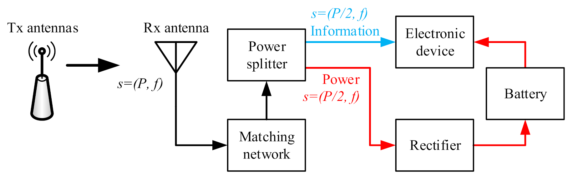
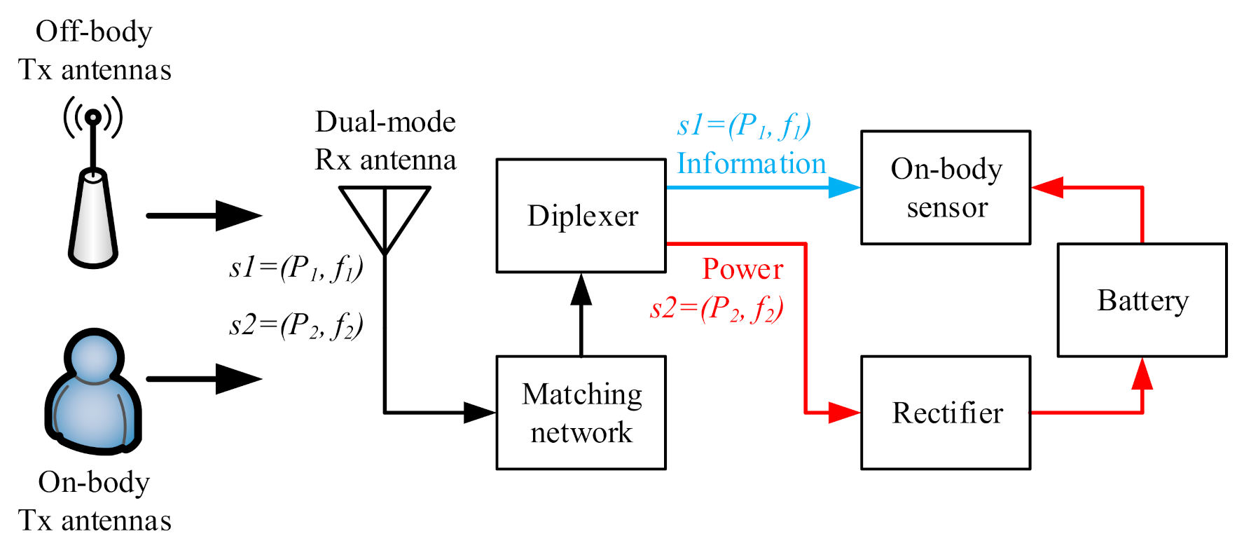
2. System Analysis
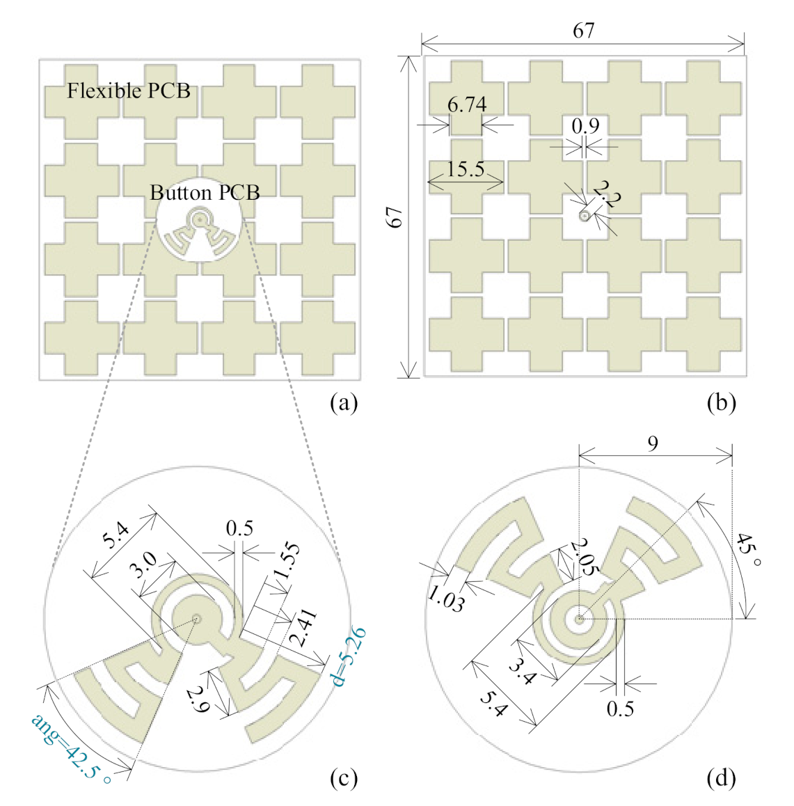
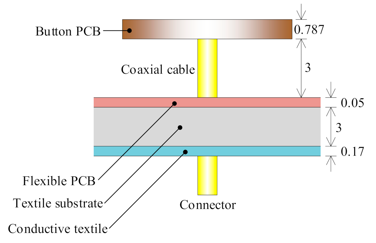
3. A Dual-Mode Wearable Button Antenna Sensor
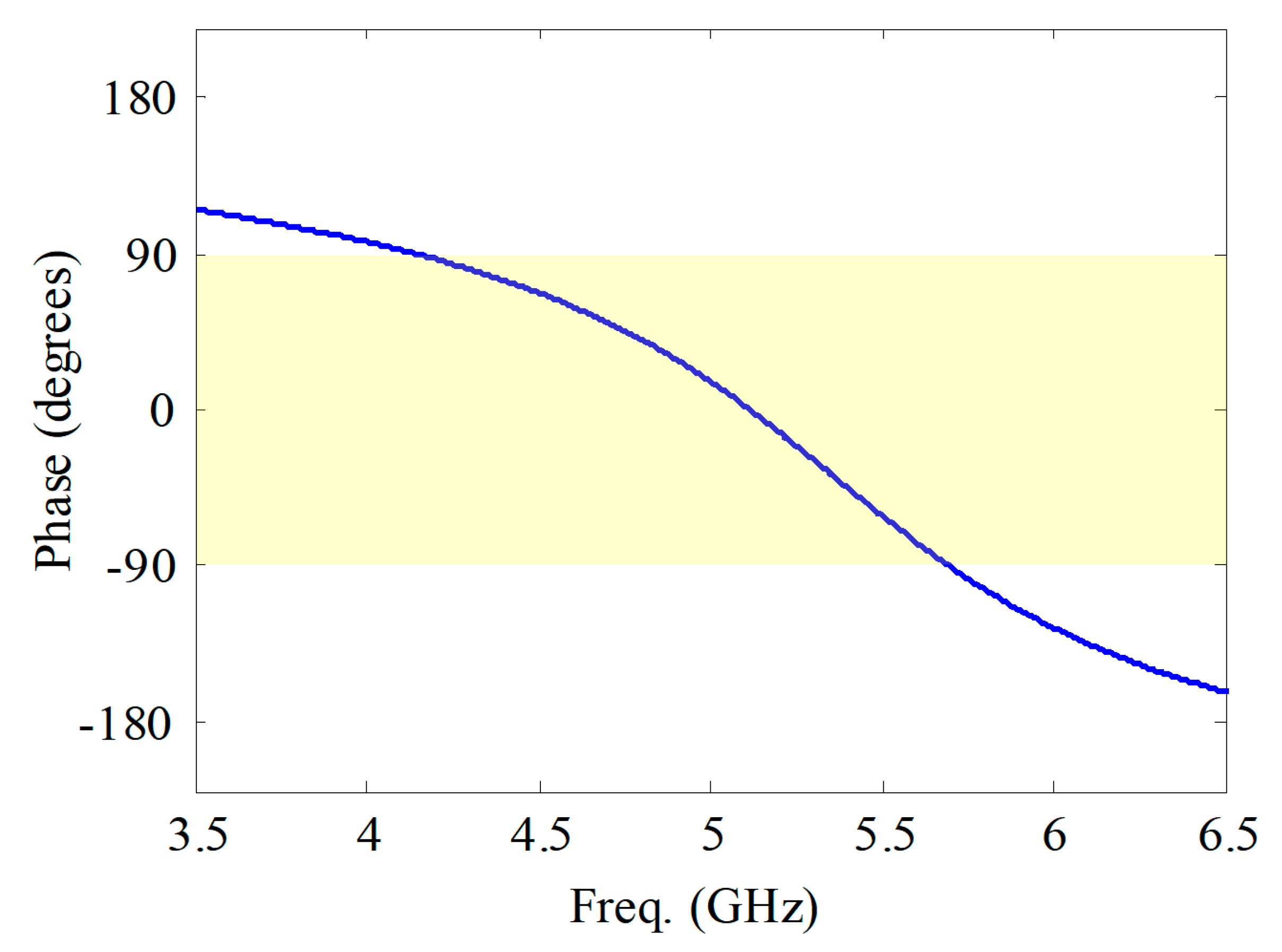
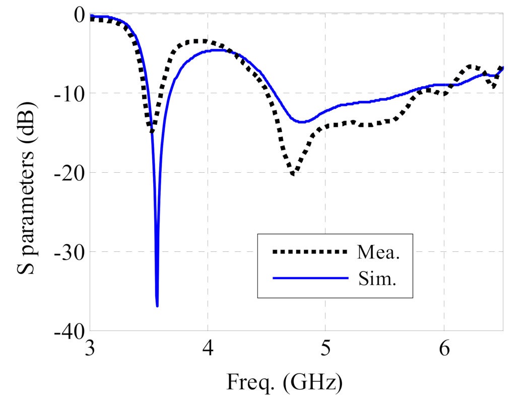
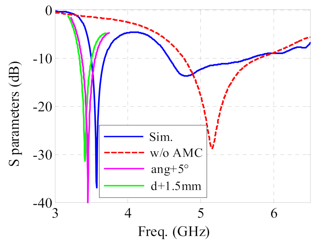
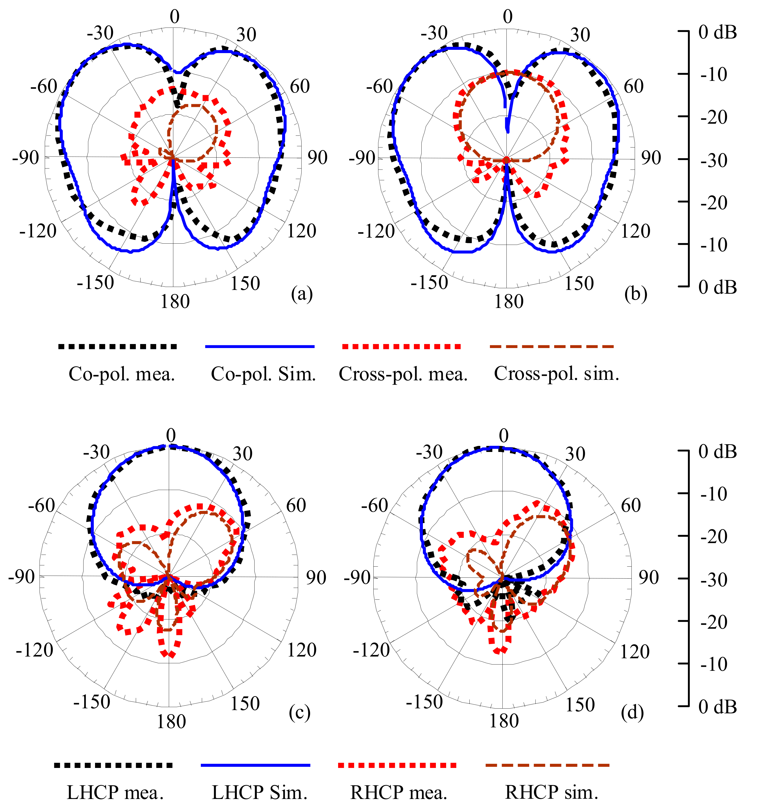
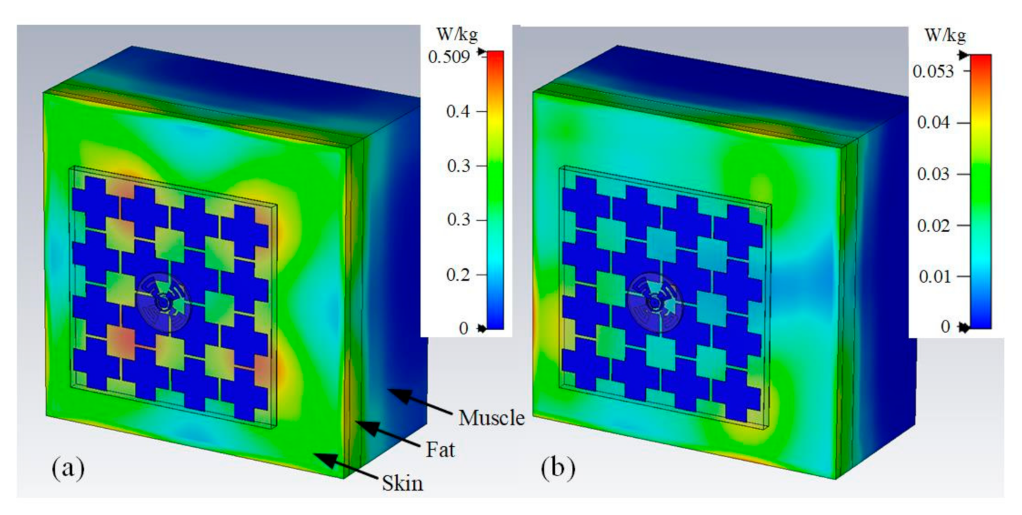
4. Prototype Performance
5. Conclusions
Author Contributions
Funding
Institutional Review Board Statement
Informed Consent Statement
Data Availability Statement
Conflicts of Interest
References
- Ayed, S.; Chaari, L.; Fares, A. A survey on trust management for WBAN: Investigations and future directions. Sensors 2020, 20, 6041. [Google Scholar] [CrossRef] [PubMed]
- Simorangkir, R.B.V.B.; Kiourti, A.; Esselle, K.P. UWB wearable antenna with a full ground plane based on PDMS-embedded conductive fabric. IEEE Antennas Wirel. Propag. Lett. 2018, 17, 493–496. [Google Scholar] [CrossRef]
- Zhang, J.; Yan, S.; Hu, X.; Vandenbosch, G.A.E. Mutual coupling suppression for on-body multi-antenna systems. IEEE Trans. Electromagn. Compat. 2020, 22, 1045–1054. [Google Scholar] [CrossRef]
- Abbasi, Q.H.; Ur-Rehman, M.; Qaraqe, K.; Alomainy, A. Advances in Body-Centric Wireless Communication: Applications and State-of-the-Art; Institution of Engineering and Technology: London, UK, 2016. [Google Scholar]
- Alqadami, A.S.; Bialkowski, K.S.; Mobashsher, A.T.; Abbosh, A.M. Wearable electromagnetic head imaging system using flexible wideband antenna array based on polymer technology for brain stroke diagnosis. IEEE Trans. Biomed. Circuits Syst. 2018, 13, 124–134. [Google Scholar] [CrossRef] [PubMed]
- Memon, A.W.; Paula, I.L.; Malengler, B.; Vasile, S.; Torre, P.V.; Langenhove, L.V. Breathable textile rectangular ring microstrip antenna at 2.45 GHz for wearable applications. Sensors 2021, 21, 1635. [Google Scholar] [CrossRef] [PubMed]
- Elias, B.B.Q.; Soh, P.J.; Al-Hadi, A.A.; Akkaraekthalin, P.; Vandenbosch, G.A.E. Bandwidth optimization of a textile PIFA with DGS using characteristic mode analysis. Sensors 2021, 21, 2516. [Google Scholar] [CrossRef] [PubMed]
- Khan, M.M.; Rahman, M.A.; Talha, M.A.; Mithila, T. Wearable antenna for power efficient on-body and off-body communications. J. Electromagn. Anal. Appl. 2014, 6, 238–243. [Google Scholar] [CrossRef]
- Azaro, R.; Debiasi, L.; Zeni, E.; Benedetti, M.; Rocca, P.; Massa, A. A hybrid prefractal three-band antenna for multistandard mobile wireless applications. IEEE Antennas Wirel. Propag. Lett. 2009, 8, 905–908. [Google Scholar] [CrossRef][Green Version]
- Li, S.; Zhou, X.; Wang, C.-X.; Yuan, D.; Zhang, W. Joint transmit power allocation and splitting for SWIPT aided OFDM-IDMA in wireless sensor networks. Sensors 2017, 17, 1566. [Google Scholar] [CrossRef]
- Chen, H.; Li, Y.; Jiang, Y.; Ma, Y.; Vucetic, B. Distributed power splitting for SWIPT in relay interference channels using game theory. IEEE Trans. Wirel. Commun. 2015, 14, 410–420. [Google Scholar] [CrossRef]
- Shadid, R.; Haerinia, M.; Roy, S.; Noghanian, S. Hybrid inductive power transfer and wireless antenna system for biomedical implanted devices. Prog. Electromagn. Res. C 2018, 88, 77–88. [Google Scholar] [CrossRef]
- Zhang, J.; Yan, S.; Vandenbosch, G.A.E. Realization of dual band pattern diversity with a CRLH-TL inspired reconfigurable metamaterial. IEEE Trans. Antennas Propag. 2018, 66, 5130–5138. [Google Scholar] [CrossRef]
- Hu, X.; Yan, S.; Vandenbosch, G.A.E. Wearable button antenna for dual-band WLAN applications with combined on and off-body radiation patterns. IEEE Trans. Antennas Propag. 2017, 65, 1384–1387. [Google Scholar]
- Adami, S.-E.; Proynov, P.; Hilton, G.S.; Yang, G.; Zhang, C.; Zhu, D.; Li, Y.; Beeby, S.P.; Craddock, I.J.; Stark, B.H. A flexible 2.45-GHz power harvesting wristband with net system output from −24.3 dBm of RF power. IEEE Trans. Microw. Theory Tech. 2018, 66, 380–395. [Google Scholar] [CrossRef]
- Shaw, T.; Samanta, G.; Mitra, D.; Mandal, B.; Augustine, R. Design of metamaterial based efficient wireless power transfer system utilizing antenna topology for werable devices. Sensors 2021, 21, 3448. [Google Scholar] [CrossRef] [PubMed]
- Zhang, J.; Meng, J.; Li, W.; Yan, S.; Vandenbosch, G.A.E. A Metamaterial Inspired Button Antenna for Wireless Power and Data Transfer. In Proceedings of the 2020 IEEE 3rd International Conference on Electronic Information and Communication Technology (ICEICT), Shenzhen, China, 13–15 November 2020; pp. 341–343. [Google Scholar]
- Lui, K.W.; Murphy, O.H.; Toumazou, C. A wearable wideband circularly polarized textile antenna for effective power transmission on a wirelessly-powered sensor platform. IEEE Trans. Antennas Propag. 2013, 61, 3873–3876. [Google Scholar] [CrossRef]
- Zhu, S.; Langley, R. Dual-Band Wearable Textile Antenna on an EBG Substrate. IEEE Trans. Antennas Propag. 2009, 57, 926–935. [Google Scholar] [CrossRef]
- Zhang, X.Y.; Wong, H.; Mo, T.; Cao, Y.F. Dual-band dual-mode button antenna for on-body and off-body communications. IEEE Trans. Biomed. Circuits Syst. 2017, 11, 933–941. [Google Scholar] [CrossRef]
- Sanz-Izquierdo, B.; Huang, F.; Batchelor, J.C. Covert dual-band wearable button antenna. Electron. Lett. 2006, 42, 3–4. [Google Scholar] [CrossRef]
- Lemey, S.; Declercq, F.; Rogier, H. Dual-band substrate integrated waveguide textile antenna with integrated solar harvester. IEEE Antennas Wirel. Propag. Lett. 2014, 13, 269–272. [Google Scholar] [CrossRef]
- Vital, D.; Bhardwaj, S.; Volakis, J.L. Textile-based large area RF-power harvesting system for wearable applications. IEEE Trans. Antennas Propag. 2020, 68, 2323–2331. [Google Scholar] [CrossRef]
- Zhang, W.; Zhuang, Y.; Song, C.; Huang, Y.; Zhou, J. A dual-band quasi-Yagi wearable antenna with high directivity. In Proceedings of the 2018 IEEE MTT-S International Wireless Symposium (IWS), Chengdu, China, 6–10 May 2018. [Google Scholar]
- Agarwal, K.; Nasimuddin; Alphones, A. RIS-based compact circularly polarized microstrip antennas. IEEE Trans. Antennas Propag. 2013, 61, 547–554. [Google Scholar] [CrossRef]
- Yin, X.; Chen, S.J.; Fumeaux, C. Wearable Dual-Band Dual-Polarization Button Antenna for WBAN Applications. IEEE Antennas Wirel. Propag. Lett. 2020, 19, 2240–2244. [Google Scholar] [CrossRef]
- Wen, L.-H.; Gao, S.; Luo, Q.; Mao, C.-X.; Hu, W.; Yin, Y.; Zhou, Y.; Wang, Q. Compact Dual-Polarized Shared-Dipole Antennas for Base Station Applications. IEEE Trans. Antennas Propag. 2018, 66, 6826–6834. [Google Scholar] [CrossRef]
- Tran, H.H.; Park, I.; Nguyen, T.K. Circularly polarized bandwidth-enhanced crossed dipole antenna with a simple single parasitic element. IEEE Antennas Wirel. Propag. Lett. 2017, 16, 1776–1779. [Google Scholar] [CrossRef]
- Pan, N.; Rajabi, M.; Claessens, S.; Schreurs, D.; Pollin, S. Transmission strategy for Simultaneous wireless information and power transfer with a non-linear rectifier model. Electronics 2020, 9, 1082. [Google Scholar] [CrossRef]
- Hu, Y.Y.; Sun, S.; Xu, H.; Sun, H. Grid-array rectenna with wide angle coverage for effectively harvesting RF Energy of low power desity. IEEE Trans. Microw. Theory Tech. 2019, 67, 402–413. [Google Scholar] [CrossRef]
- Chen, C.M.; Volski, V.; Van der Perre, L.; Vandenbosch, G.A.E.; Pollin, S. Finite large antenna arrays for Massive MIMO: Characterization and system impact. IEEE Trans. Antennas Propag. 2017, 65, 6712–6720. [Google Scholar] [CrossRef]
- Utsav, A.; Kumar, A.; Badhai, R.K.; Suraj, P. A dual band on body monopole antenna for WiMAX and X-band applications. In Proceedings of the 2018 International Conference for Convergence in Technology (I2CT), Pune, India, 6–7 April 2018. [Google Scholar]
- Microwave Studio. Computer Simulation Technology (CST). 2016. Available online: http://www.cst.com/Products/CSTMWS/ (accessed on 24 June 2021).
- Yan, S.; Vandenbosch, G.A.E. Radiation pattern-reconfigruable wearable antenna based on metamaterial structure. IEEE Antennas Wirel. Propag. Lett. 2016, 15, 1715–1718. [Google Scholar] [CrossRef]
- Agarwal, K.; Guo, Y.-X.; Salam, B. Wearable AMC backed near-endfire antenna for on-body communications on latex substrate. IEEE Trans. Compon. Packag. Manuf. Technol. 2016, 6, 346–358. [Google Scholar] [CrossRef]
- Raad, H.R.; Abbosh, A.I.; Al-Rizzo, H.M.; Rucker, D.G. Flexible and compact AMC based antenna for telemedicine applications. IEEE Trans. Antennas Propag. 2013, 61, 524–531. [Google Scholar] [CrossRef]
- Vandenbosch, G.A.E.; Mioc, F.; Saporetti, M.; Foged, L. Bridging the simulations—measurements gap: State-of-the-art. IEEE Antennas Propag. Mag. 2016, 58, 12–24. [Google Scholar] [CrossRef]
- IEEE.IEEE C95.1-2019. 2019. Available online: http://standards.ieee.org/standard/C95_1-2019.html (accessed on 24 June 2021).


| Freq. (GHz) | Realized Gain | Radiation Efficiency | ||
|---|---|---|---|---|
| Sim. | Mea. | Sim. | Mea. | |
| 3.55 GHz | 2.7 dBi | 2.9 dBi | 87% | 90% |
| 5.0 GHz | 7.9 dBi | 8.4 dBi | 83% | 90% |
| 5.5 GHz | 7.2 dBi | 7.9 dBi | 81% | 87% |
| Ref. | Freq. Band | Dual-Band | Circularly Polarized | Efficiency (Sim.) in % | Radiator Size in λ2 | Antenna Size in λ2 | Bending Analysis | Tilting Analysis | |
|---|---|---|---|---|---|---|---|---|---|
| in GHz | Mea. | ||||||||
| [15] | 2.45 | N/A | No | No | 70 | 0.36 × 0.41 | 0.44 × 0.49 | Yes | No |
| [18] | 1.94–3.03 | 43.7 | No | Yes | 55 | 0.49 × 0.49 | 0.49 × 0.49 | Yes | No |
| [19] | 2.45/5.40–6.15 | 4/12 | Yes | No | N/A | 0.44 × 0.44 | 0.98 × 0.98 | Yes | No |
| [22] | ca. 2.36–2.72 | 14.2 | No | No | 75 | N/A | 0.73 × 0.98 | Yes | No |
| [23] | ca. 2.43–2.48 | 2.0 | No | No | 89 | 0.44 × 0.30 | 0.55 × 0.57 | No | No |
| [24] | 2.23–2.66/4.62–5.07 | 17.6/9.3 | Yes | No | N/A | 0.34 × 0.36 | 0.36 × 0.41 | Yes | No |
| [25] | 2.47–2.60 | 5.2 | No | Yes | N/A | 0.17 × 0.17 | 0.29 × 0.29 | No | No |
| [26] | 2.39–2.57/4.80–8.18 | 7.3/52.1 | Yes | Yes | N/A | 0.15 × 0.15 | 0.51 × 0.51 | Yes | Yes |
| This work | 3.47–3.61/4.51–5.80 | 4.0/25.0 | Yes | Yes | 90 / 87 | 0.21 × 0.21 | 0.78 × 0.78 | Yes | Yes |
Publisher’s Note: MDPI stays neutral with regard to jurisdictional claims in published maps and institutional affiliations. |
© 2021 by the authors. Licensee MDPI, Basel, Switzerland. This article is an open access article distributed under the terms and conditions of the Creative Commons Attribution (CC BY) license (https://creativecommons.org/licenses/by/4.0/).
Share and Cite
Zhang, J.; Meng, J.; Li, W.; Yan, S.; Vandenbosch, G.A.E. A Wearable Button Antenna Sensor for Dual-Mode Wireless Information and Power Transfer. Sensors 2021, 21, 5678. https://doi.org/10.3390/s21175678
Zhang J, Meng J, Li W, Yan S, Vandenbosch GAE. A Wearable Button Antenna Sensor for Dual-Mode Wireless Information and Power Transfer. Sensors. 2021; 21(17):5678. https://doi.org/10.3390/s21175678
Chicago/Turabian StyleZhang, Jiahao, Jin Meng, Wei Li, Sen Yan, and Guy A. E. Vandenbosch. 2021. "A Wearable Button Antenna Sensor for Dual-Mode Wireless Information and Power Transfer" Sensors 21, no. 17: 5678. https://doi.org/10.3390/s21175678
APA StyleZhang, J., Meng, J., Li, W., Yan, S., & Vandenbosch, G. A. E. (2021). A Wearable Button Antenna Sensor for Dual-Mode Wireless Information and Power Transfer. Sensors, 21(17), 5678. https://doi.org/10.3390/s21175678