
SpecTalk: Conforming IoT Implementations to Sensor Specifications


Abstract
:1. Introduction
2. Taiwan Association of Information and Communication Standards
- Advanced Mobile Communication
- Network Communication
- Device Internetworking
- Audiovisual Services and Communications
- Network and Information Security
- Intelligent Buildings ICT
- Internet of Vehicles (IoV) and Automated Driving
- Hsinchu International AI Smart Park
- Smart Campus of China Medical University in the Shuinan Trade and Economic Park, Taichung
- The Telecommunication Technology Committee (TTC), Japan
- The Telecommunications Industry Association (TIA), USA
- Institute of Electrical and Electronics Engineers (IEEE), USA
- China Communications Standards Association (CCSA), China
- European Telecommunications Standards Institute (ETSI), EU
- The Association of Radio Industries and Businesses (ARIB), Japan
- Telecommunications Standards Development Society (TSDSI), India
- Malaysian Technical Standards Forum Bhd (MTSFB), Malaysia
- Telecommunications Technology Association (TTA), Korea
3. The SpecTalk Architecture and Procedures
3.1. Construction of the SpecTalk Database
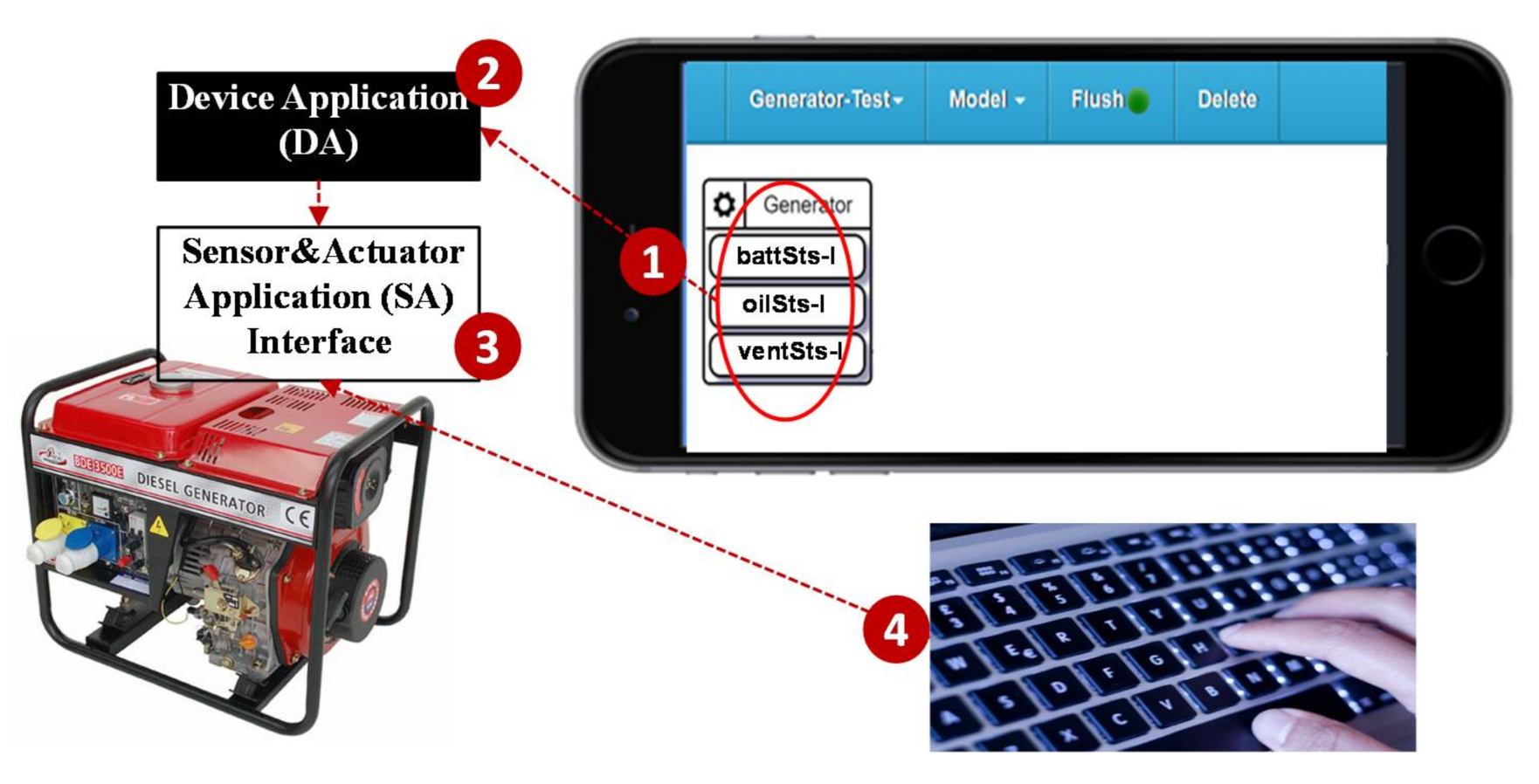
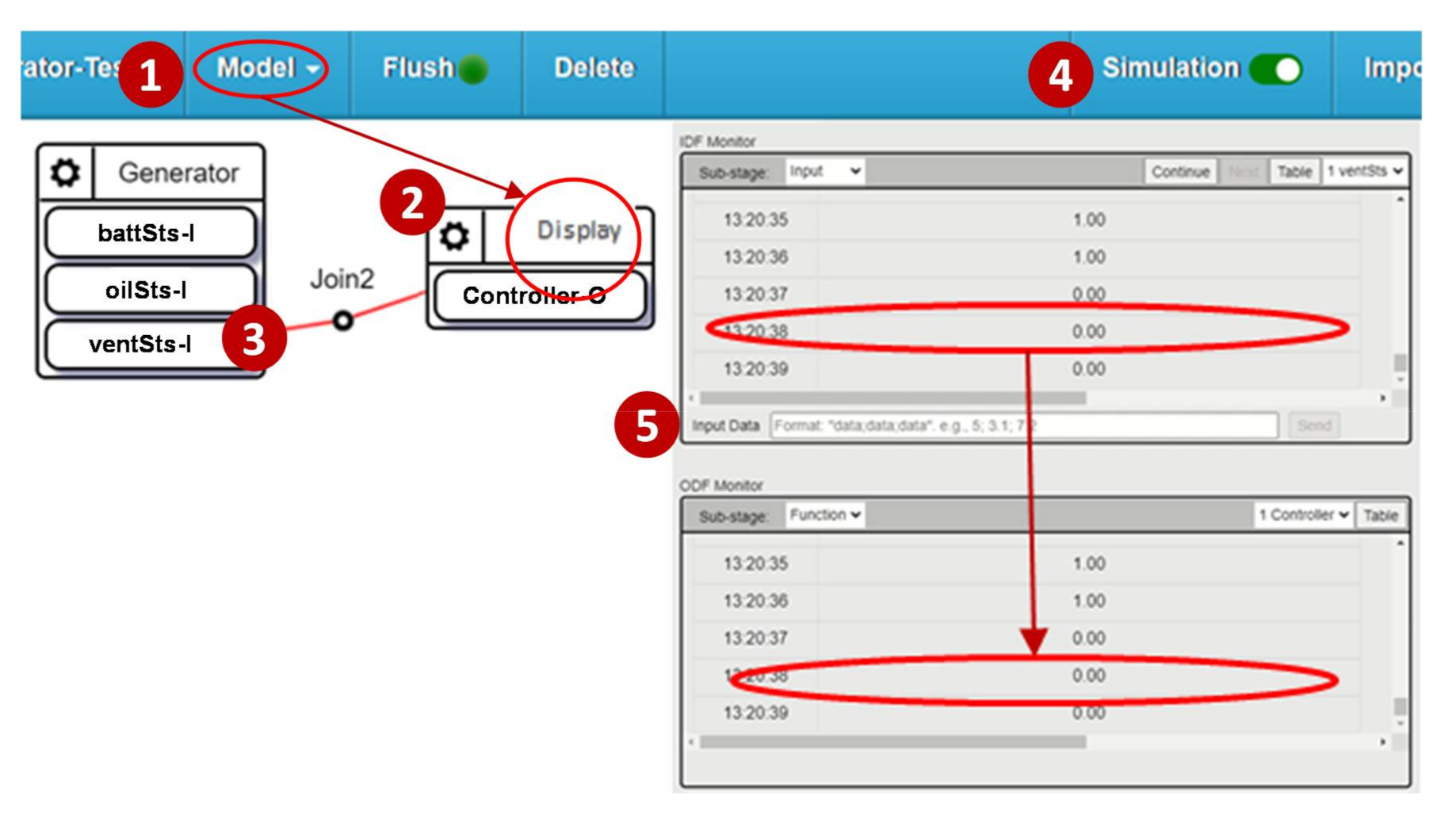
3.2. Generation of the SA Interface
- 01.
- import time, random, requests
- 02.
- import DA
- 03.
- import Your-API
- 04.
- ServerURL = ‘https://DomainName’
- 05.
- Reg_addr = “GEN-0012”
- 06.
- DA.profile[‘dm_name’] = ‘Generator’
- 07.
- DA.profile[‘df_list’] = [‘oilSts-I’, ‘battSts-I’, ‘ventSts-I’,]
- 08.
- DA.profile[‘d_name’] = ‘Your-Device-Name’
- 09.
- DA.register(ServerURL, Reg_addr)
- 10.
- while True:
- 11.
- try:
- 12.
- oilSts _data = Your-oilSts-function
- 13.
- DA.push (‘ oilSts-I ‘, oilSts _data)
- 14.
- battSts _data = Your- battSts -function
- 15.
- DA.push (‘battSts-I’, battSts _data)
- 16.
- ventSts _data = Your- ventSts -function
- 17.
- DA.push (‘ventSts-I’, ventSts _data)
- 18.
- except Exception as e:
- 19.
- print(e)
- 20.
- if str(e).find(‘mac_addr not found:’) ! = −1:
- 21.
- print(‘Reg_addr is not found. Try to re-register.’)
- 22.
- DA.register (ServerURL, Reg_addr)
- 23.
- else:
- 24.
- print(‘Connection fails.’)
- 25.
- time.sleep(1)
- 26.
- time.sleep(0.2)
4. The SpecTalk Acceptance Tests
- Self-test involves the IoT DUT only
- Mutual-test involves two or more IoT DUTs
- Visual-test involves the IoT DUTs and a monitoring camera
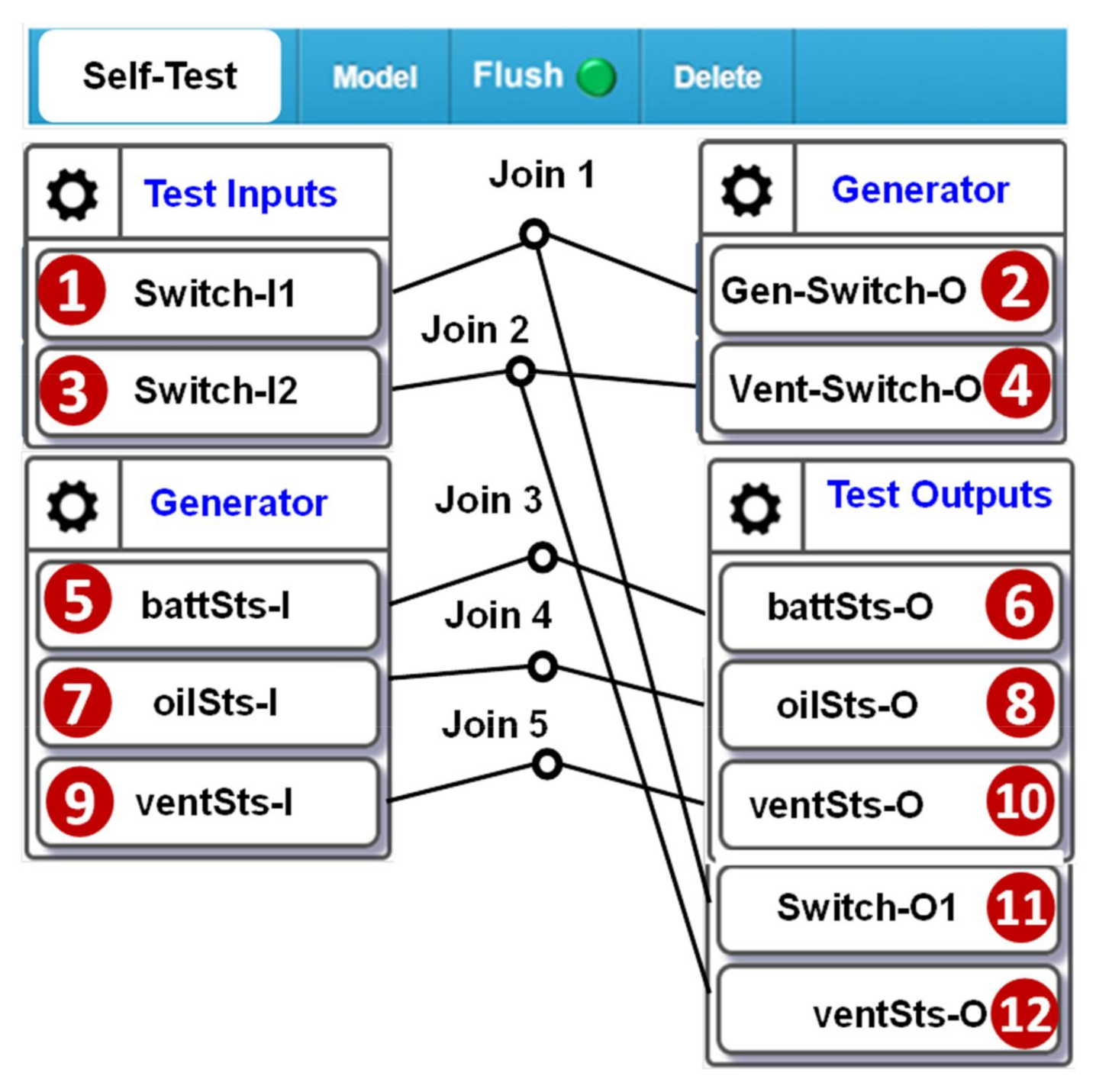
4.1. Self-Test
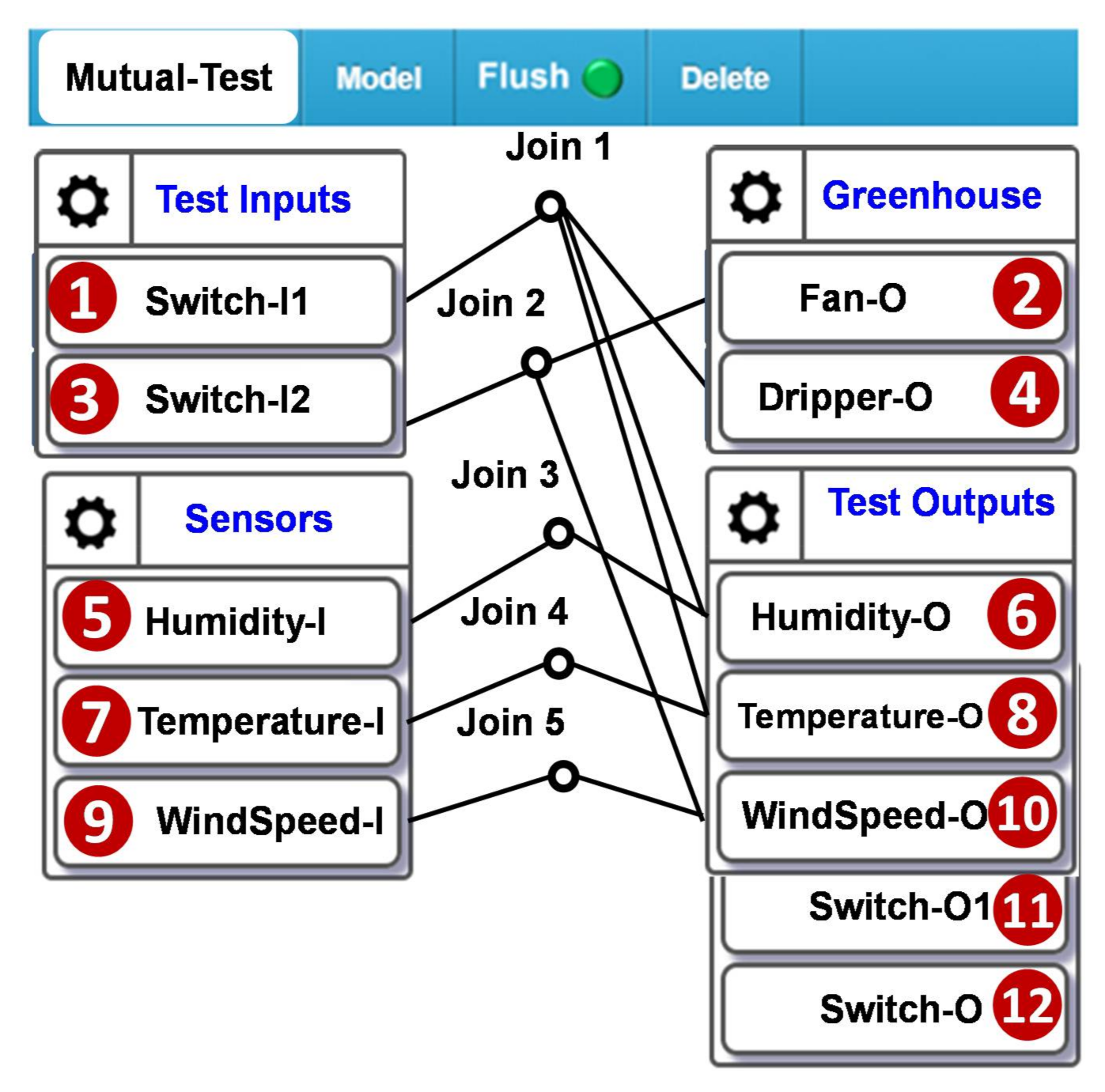
4.2. Mutual-Test
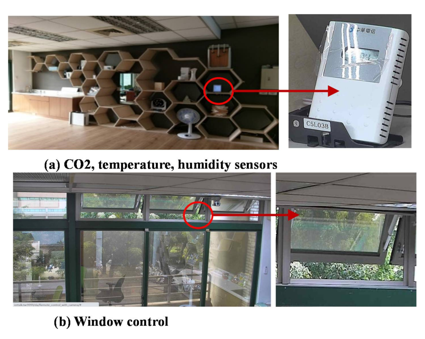
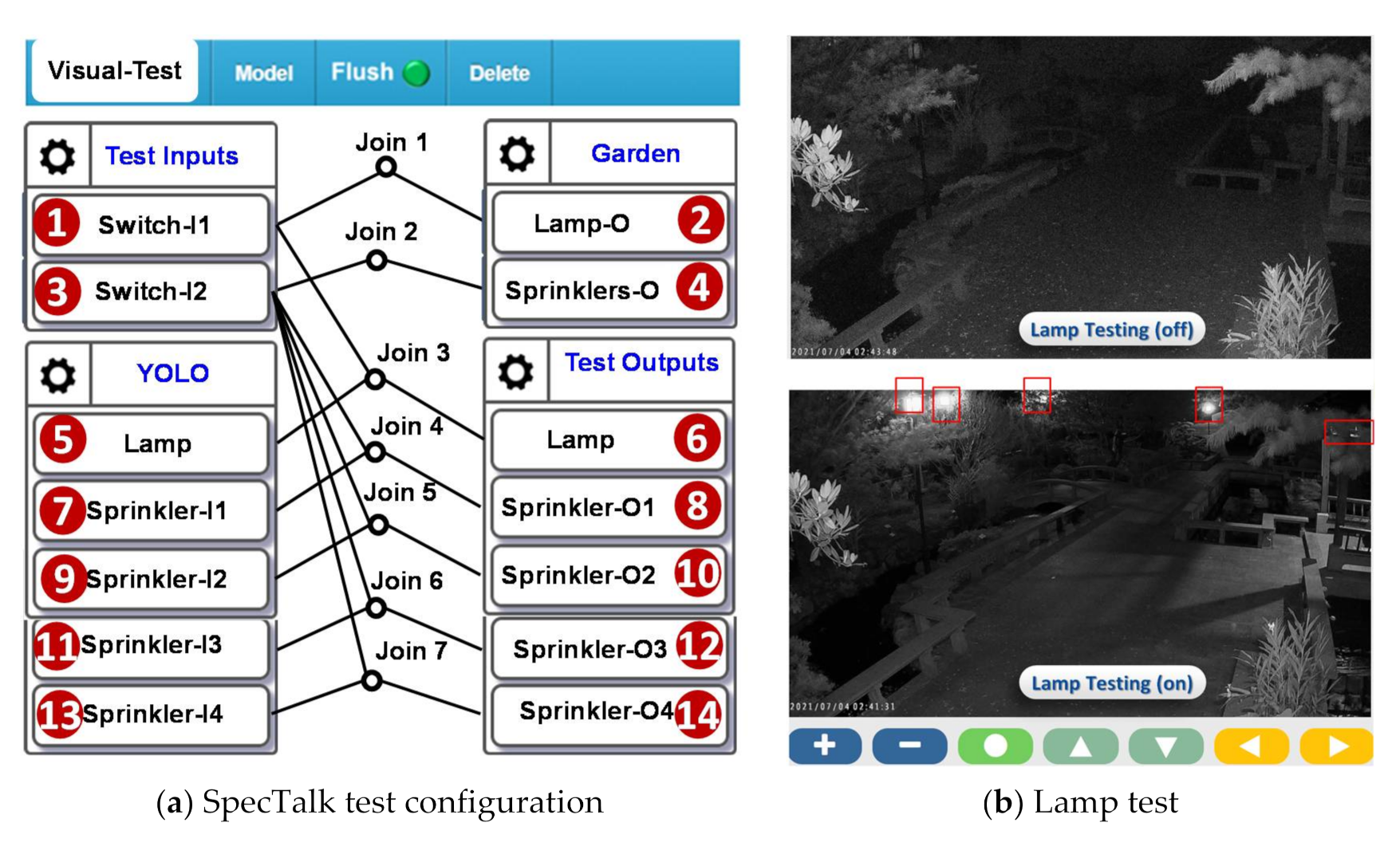
4.3. Visual-Test
5. Selection of the Frequency of the Control Signals in the IoT Device Test
6. Conclusions
Author Contributions
Funding
Conflicts of Interest
References
- oneM2M, Functional Architecture, TS-0001. Available online: http://www.onem2m.org/technical/published-drafts (accessed on 15 July 2021).
- oneM2M, Base Ontology, TS-0012. Available online: http://www.onem2m.org/technical/publisheddrafts (accessed on 15 July 2021).
- Allied Market Research. Smart Building Market. Allied Market Research. Available online: https://www.alliedmarketresearch.com/smart-building-market (accessed on 15 July 2021).
- Williams, V.; Terence, S.; Immaculate, J. Survey on Internet of Things based Smart Home. In Proceedings of the 2019 International Conference on Intelligent Sustainable Systems (ICISS), Palladam, India, 21–22 February 2019. [Google Scholar]
- Almusaylim, Z.A.; Zaman, N. A review on smart home present state and challenges: Linked to context-awareness internet of things (IoT). Wirel. Netw. 2019, 25, 3193–3204. [Google Scholar] [CrossRef]
- ISTQB. Standard Glossary of Terms used in Software Testing, Version 3.2: All Terms; International Software Testing Qualifications Board: Brussels, Belgium, 2020. [Google Scholar]
- Chen, F.; Zhou, G. RRM conformance testing in TD-LTE system based on TTCN-3. In Proceedings of the International Conference on Information and Automation (ICIA), Yinchuan, China, 26–28 August 2013. [Google Scholar]
- Szabados, K.; Kovács, A.; Jenei, G.; Góbor, D. Titanium: Visualization of TTCN-3 system architecture. In Proceedings of the IEEE International Conference on Automation, Quality and Testing, Robotics, AQTR, Cluj-Napoca, Romania, 19–21 May 2016. [Google Scholar]
- Caserta, P.; Zendra, O. Visualization of the Static Aspects of Software: A Survey. IEEE Trans. Vis. Comput. Graph. 2011, 17, 913–933. [Google Scholar] [CrossRef] [PubMed] [Green Version]
- Santos, I.; Filho, J.C.C.; Souza, S.R.S. A survey on the practices of mobile application testing. In Proceedings of the 2020 XLVI Latin American Computing Conference (CLEI), Loja, Ecuador, 19–23 October 2020. [Google Scholar]
- Akpinar, P.; Aktas, M.S.; Keles, A.B.; Balaman, Y.; Guler, Z.O.; Kali, O. Web Application Testing With Model Based Testing Method: Case Study. In Proceedings of the International Conference on Electrical, Communication, and Computer Engineering (ICECCE), Istanbul, Turkey, 12–13 June 2020. [Google Scholar]
- BACnet—A Data Communication Protocol for Building Automation and Control Networks, ASHRAE SSPC 135. Available online: http://www.bacnet.org/ (accessed on 15 July 2021).
- TACIS. Data Format Standard and Test Specification for Intelligent Building Energy Management System v2, TACIS TS-0022; Taiwan Association of Information and Communication Standards (TAICS): Taipei City, Taiwan, 2021. [Google Scholar]
- MODBUS. MODBUS Application Protocol Specification V1.1b3. Available online: http://www.modbus.org/docs/Modbus_Application_Protocol_V1_1b3.pdf (accessed on 15 July 2021).
- IETF. Hypertext Transfer Protocol—HTTP/1.1, IETF RFC 2616, Internet Engineering Task Force. Available online: https://tools.ietf.org/html/rfc2616 (accessed on 15 July 2021).
- W3C. XML Schema Part 2: Datatypes Second Edition, W3C Recommendation 28 October 2004. Available online: https://www.w3.org/TR/xmlschema-2/ (accessed on 15 July 2021).
- ECMA. The JSON Data Interchange Syntax, ECMA-404, European Computer Manufacturers Association. Available online: http://www.ecma-international.org/publications/files/ECMA-ST/ECMA-404.pdf (accessed on 15 July 2021).
- ECMA. Introducing JSON, European Computer Manufacturers Association. Available online: https://www.json.org/index.html (accessed on 15 July 2021).
- Lin, Y.-B.; Lin, Y.-W.; Huang, C.-M.; Chih, C.-Y.; Lin, P. IoTtalk: A Management Platform for Reconfigurable Sensor Devices. IEEE Internet Things J. 2017, 4, 1552–1562. [Google Scholar] [CrossRef]
- Zeng, X.; Garg, S.K.; Strazdins, P.; Jayaraman, P.P.; Georgakopoulos, D.; Ranjan, R. IOTSim: A simulator for analysing IoT applications. J. Syst. Archit. 2017, 72, 93–107. [Google Scholar] [CrossRef]
- Fortino, G.; Russo, W.; Savagliom, C. Agent-Oriented Modeling and Simulation of IoT Networks. In Proceedings of the 2016 Federated Conference on Computer Science and Information Systems (FedCSIS), Gdansk, Poland, 11–14 September 2016. [Google Scholar]
- Lin, Y.-W.; Lin, Y.-B.; Yen, T.-H. SimTalk: Simulation of IoT Applications. Sensors 2020, 20, 2563. [Google Scholar] [CrossRef] [PubMed]
- Lin, Y.-B.; Lin, Y.-W.; Lin, J.-Y.; Hung, H.-N. SensorTalk: An IoT Device Failure Detection and Calibration Mechanism for Smart Farming. Sensors 2019, 19, 4788. [Google Scholar] [CrossRef] [PubMed] [Green Version]
- Usmani, R.S.A.; Saeed, A.; Abdullahi, A.M.; Pillai, T.R.; Jhanjhi, N.Z.; Hashem, I.A.T. Air pollution and its health impacts in Malaysia: A review. Air Qual. Atmos. Health 2020, 13, 1093–1118. [Google Scholar] [CrossRef]
- Long, X.; Deng, K.; Wang, G.; Zhang, Y.; Dang, Q.; Guo, Y.; Shen, H.; Ren, J.; Han, S.; Ding, E.; et al. PP-YOLO: An Effective and Efficient Implementation of Object Detector. arXiv 2020, arXiv:2007.12099. [Google Scholar]
- Lin, Y.-B.; Chlamtac, I. Heterogeneous Personal Communications Services: Integration of PCS Systems. IEEE Commun. Mag. 1996, 3, 106–113. [Google Scholar]
- Lin, Y.-B.; Chuang, Y.-M. Modeling the Sleep Mode for Cellular Digital Packet Data. IEEE Commun. Lett. 1999, 3, 63–65. [Google Scholar]
- Lazowska, E.D.; Zahorjan, J.; Graham, G.S.; Sevcik, K.C. Quantitative System Performance: Computer System Analysis Using Queueing Network Models; Prentice-Hall, Inc.: Englewood Cliffs, NJ, USA, 1984. [Google Scholar]


Publisher’s Note: MDPI stays neutral with regard to jurisdictional claims in published maps and institutional affiliations. |
© 2021 by the authors. Licensee MDPI, Basel, Switzerland. This article is an open access article distributed under the terms and conditions of the Creative Commons Attribution (CC BY) license (https://creativecommons.org/licenses/by/4.0/).
Share and Cite
Lin, Y.-B.; Chou, S.-L. SpecTalk: Conforming IoT Implementations to Sensor Specifications. Sensors 2021, 21, 5260. https://doi.org/10.3390/s21165260
Lin Y-B, Chou S-L. SpecTalk: Conforming IoT Implementations to Sensor Specifications. Sensors. 2021; 21(16):5260. https://doi.org/10.3390/s21165260
Chicago/Turabian StyleLin, Yi-Bing, and Sheng-Lin Chou. 2021. "SpecTalk: Conforming IoT Implementations to Sensor Specifications" Sensors 21, no. 16: 5260. https://doi.org/10.3390/s21165260
APA StyleLin, Y.-B., & Chou, S.-L. (2021). SpecTalk: Conforming IoT Implementations to Sensor Specifications. Sensors, 21(16), 5260. https://doi.org/10.3390/s21165260