
A Model for the Magnetoimpedance Effect in Non-Symmetric Nanostructured Multilayered Films with Ferrogel Coverings


Abstract
:1. Introduction
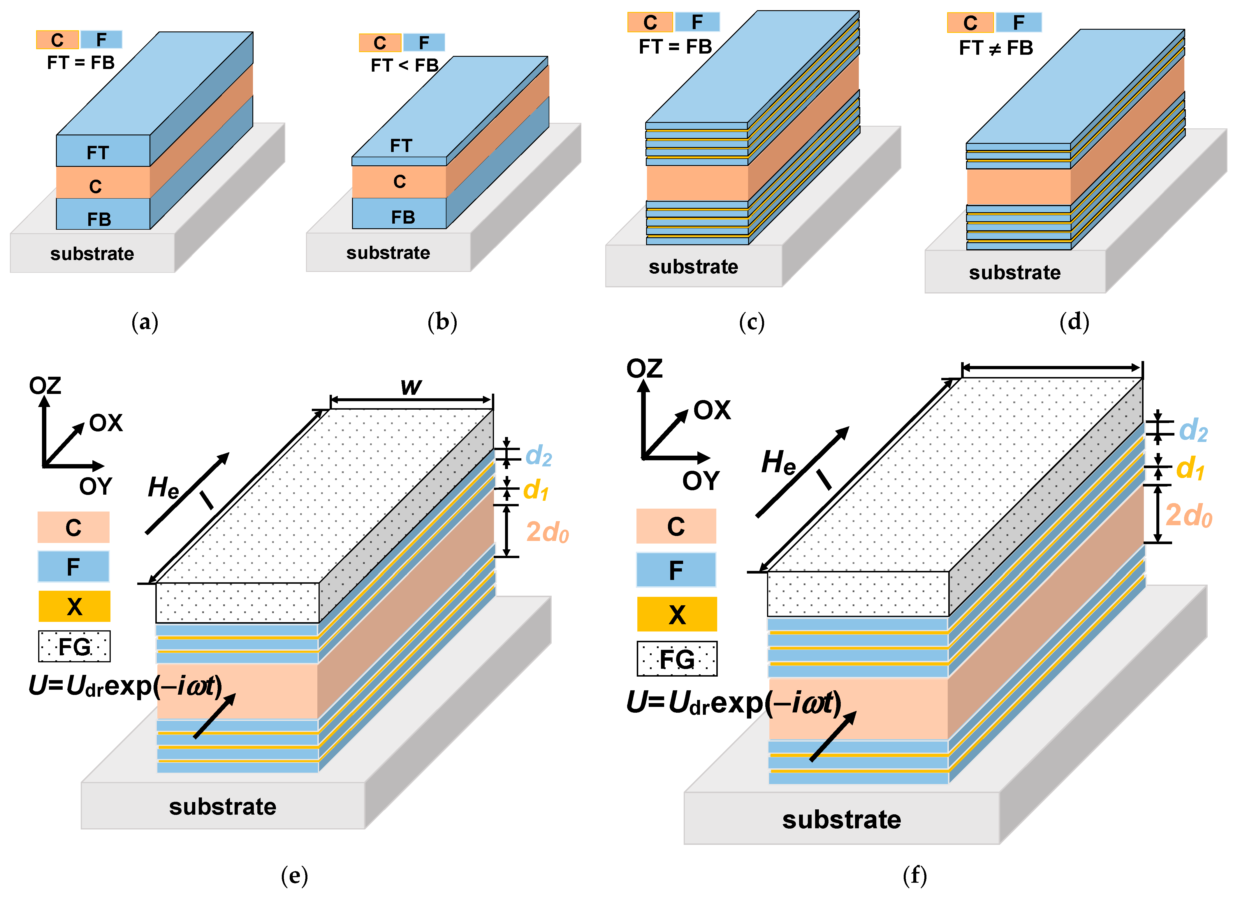
2. Model
2.1. Field Disrtibution and MI in Multilayer–Ferrogel Structure
2.2. Static Magnetization Distribution and Transverese Permeability
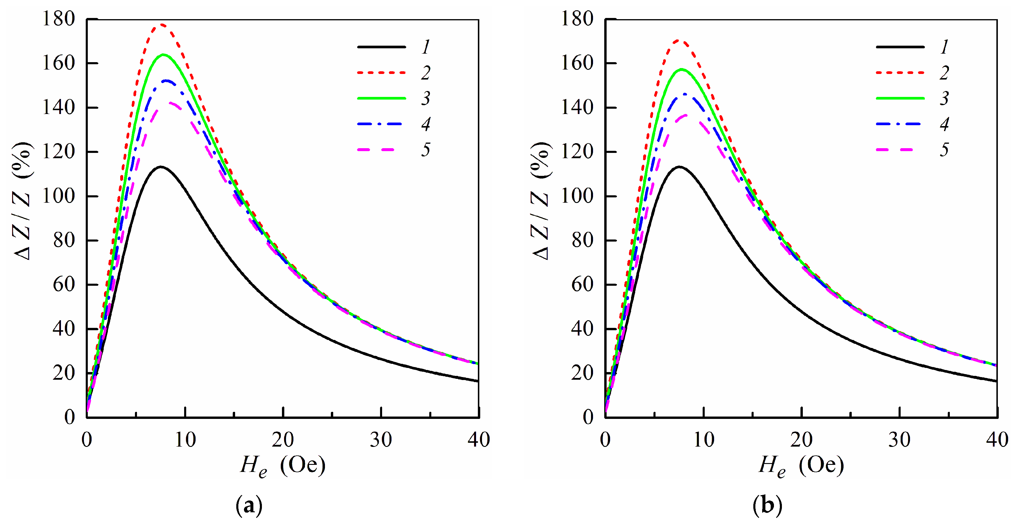
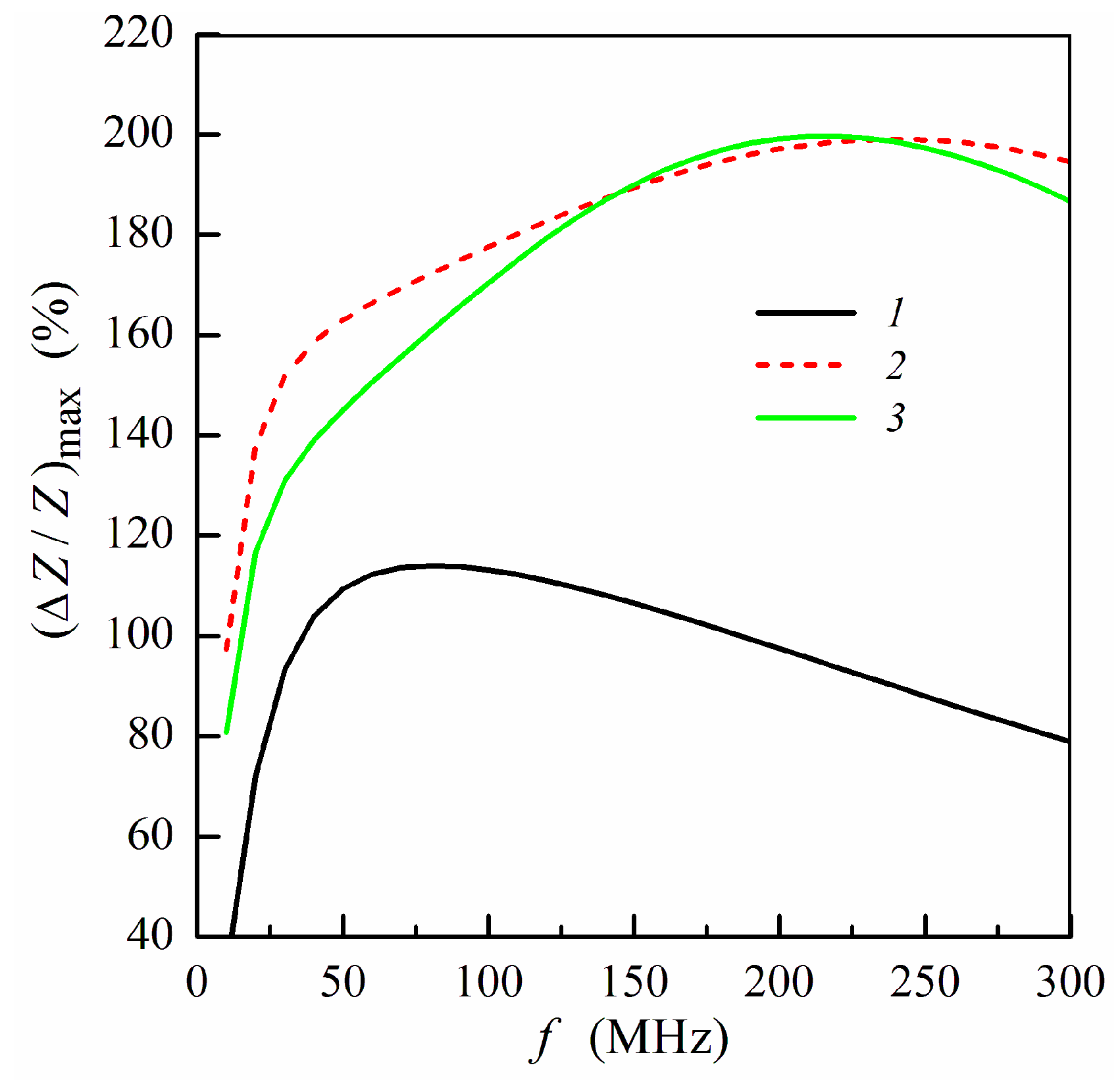
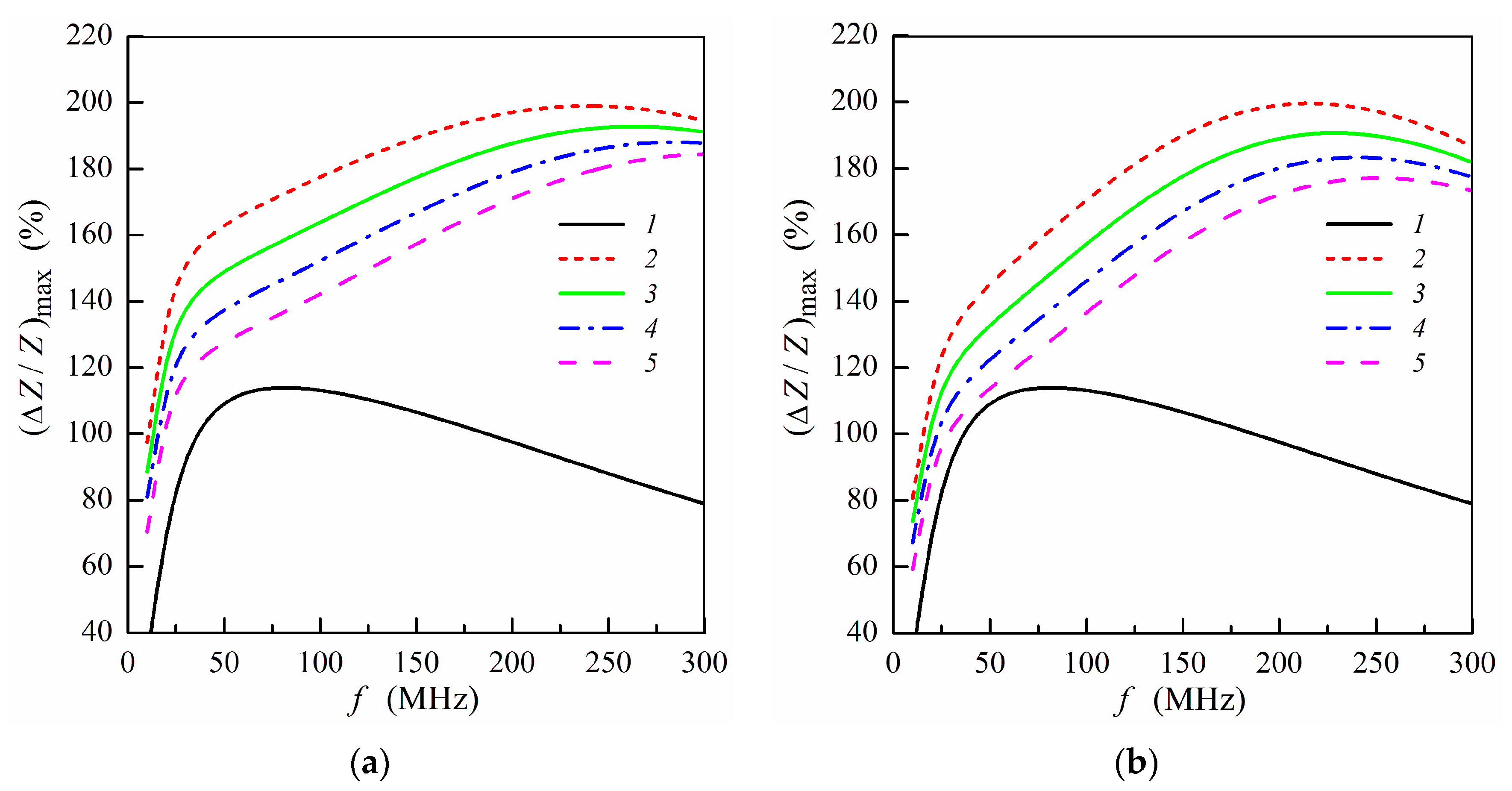
3. Results
4. Discussion
5. Conclusions
Author Contributions
Funding
Institutional Review Board Statement
Informed Consent Statement
Data Availability Statement
Acknowledgments
Conflicts of Interest
References
- Baselt, D.R.; Lee, G.U.; Natesan, M.; Metzger, S.W.; Sheehan, P.E.; Colton, R. A biosensor based on magnetoresistance technology. Biosens. Bioelectron. 1998, 13, 731–739. [Google Scholar] [CrossRef]
- Cardoso, S.; Leitao, D.C.; Dias, T.M.; Valadeiro, J.; Silva, M.D.; Chicharo, A.; Silverio, V.; Gaspar, J.; Freitas, P.P. Challenges and trends in magnetic sensor integration with microfluidics for biomedical applications. J. Phys. D Appl. Phys. 2017, 50, 213001. [Google Scholar] [CrossRef]
- Grimes, C.A.; Mungle, C.S.; Zeng, K.; Jain, M.K.; Dreschel, W.R.; Paulose, M.; Ong, G.K. Wireless magnetoelastic resonance sensors: A critical review. Sensors 2002, 2, 294–313. [Google Scholar] [CrossRef] [Green Version]
- Marín, P.; Marcos, M.; Hernando, A. High magnetomechanical coupling on magnetic microwire for sensors with biological applications. Appl. Phys. Lett. 2010, 96, 262512. [Google Scholar] [CrossRef] [Green Version]
- Kurlyandskaya, G.V.; Portnov, D.S.; Beketov, I.V.; Larrañaga, A.; Safronov, A.P.; Orue, I.; Medvedev, A.I.; Chlenova, A.A.; Sanchez-Ilarduya, M.B.; Martinez-Amesti, A.; et al. Nanostructured materials for magnetic biosensing. Biochim. Biophys. Acta (BBA) Gen. Subj. 2017, 1861, 1494–1506. [Google Scholar] [CrossRef]
- Beato-López, J.J.; Pérez-Landazábal, J.I.; Gómez-Polo, C. Magnetic nanoparticle detection method employing non-linear magnetoimpedance effects. J. Appl. Phys. 2017, 121, 163901. [Google Scholar] [CrossRef]
- Schmalz, J.; Kittmann, A.; Durdaut, P.; Spetzler, B.; Faupel, F.; Hoft, M.; Quandt, E.; Gerken, M. Multi-mode love-wave SAW magnetic-field sensors. Sensors 2020, 20, 3421. [Google Scholar] [CrossRef] [PubMed]
- Li, M.; Matyushov, A.; Dong, C.; Chen, H.; Lin, H.; Nan, T.; Qian, Z.; Rinaldi, M.; Lin, Y.; Sun, N.X. Ultra-sensitive NEMS magnetoelectric sensor for picotesla DC magnetic field detection. Appl. Phys. Lett. 2017, 110, 143510. [Google Scholar] [CrossRef]
- Kurlyandskaya, G.V.; Levit, V.I. Advanced materials for drug delivery and biosensors based on magnetic label detection. Mater. Sci. Eng. C 2007, 27, 495–503. [Google Scholar] [CrossRef]
- Wang, T.; Guo, L.; Lei, C.; Zhou, Y. Ultrasensitive determination of carcinoembryonic antigens using a magnetoimpedance immunosensor. RSC Adv. 2015, 5, 51330–51336. [Google Scholar] [CrossRef]
- Yang, Z.; Wang, H.H.; Dong, X.W.; Yan, H.L.; Lei, C.; Luo, Y.S. Giant magnetoimpedance based immunoassay for cardiac biomarker myoglobin. Anal. Methods 2017, 9, 3636–3642. [Google Scholar] [CrossRef]
- Chiriac, H.; Herea, D.D.; Corodeanu, S. Microwire array for giant magnetoimpedance detection of magnetic particles for biosensor prototype. J. Magn. Magn. Mater. 2007, 311, 425–428. [Google Scholar] [CrossRef]
- Kumar, A.; Mohapatra, S.; Fal-Miyar, V.; Cerdeira, A.; Garcia, J.A.; Srikanth, H.; Gass, J.; Kurlyandskaya, G.V. Magnetoimpedance biosensor for Fe3O4 nanoparticle intracellular uptake evaluation. Appl. Phys. Lett. 2007, 91, 143902. [Google Scholar] [CrossRef] [Green Version]
- Devkota, J.; Howell, P.; Mukherjee, P.; Srikanth, H.; Mohapatra, S.; Phan, M.H. Magneto-reactance based detection of MnO nanoparticle-embedded Lewis lung carcinoma cells. J. Appl. Phys. 2015, 117, 17D123. [Google Scholar] [CrossRef]
- Blanc-Béguin, F.; Nabily, S.; Gieraltowski, J.; Turzo, A.; Querellou, S.; Salaun, P.Y. Cytotoxicity and GMI bio-sensor detection of maghemite nanoparticles internalized into cells. J. Magn. Magn. Mater. 2009, 321, 192–197. [Google Scholar] [CrossRef]
- García-Arribas, A.; Martínez, F.; Fernández, E.; Ozaeta, I.; Kurlyandskaya, G.V.; Svalov, A.V.; Berganzo, J.; Barandiaran, J.M. GMI detection of magnetic-particle concentration in continuous flow. Sens. Actuators A 2011, 172, 103–108. [Google Scholar] [CrossRef]
- Kurlyandskaya, G.V.; Fernandez, E.; Safronov, A.P.; Svalov, A.V.; Beketov, I.V.; Burgoa Beitia, A.; Garcıa-Arribas, A.; Blyakhman, F.A. Giant magnetoimpedance biosensor for ferrogel detection: Model system to evaluate properties of natural tissue. Appl. Phys. Lett. 2015, 106, 193702. [Google Scholar] [CrossRef]
- Safronov, A.P.; Mikhnevich, E.A.; Lotfollahi, Z.; Blyakhman, F.A.; Sklyar, T.F.; Larrañaga Varga, A.; Medvedev, A.I.; Fernández Armas, S.; Kurlyandskaya, G.V. Polyacrylamide ferrogels with magnetite or strontium hexaferrite: Next step in the development of soft biomimetic matter for biosensor applications. Sensors 2018, 18, 257. [Google Scholar] [CrossRef] [PubMed] [Green Version]
- Uchiyama, T.; Mohri, K.; Honkura, Y.; Panina, L.V. Recent advances of pico-Tesla resolution magnetoimpedance sensor based on amorphous wire CMOS IC MI Sensor. IEEE Trans. Magn. 2012, 48, 3833–3839. [Google Scholar] [CrossRef]
- Sandhu, A.; Southern, P.; de Freitas, S.C.; Knudde, S.; Cardoso, F.A.; Freitas, P.P.; Kurlyandskaya, G.V. Sensing Magnetic Nanoparticles 172–227 in Magnetic Nanoparticles in Biosensing and Medicine Ed; Nicholas, J.D., Adrian, I., Justin, L., Eds.; Cambridge University Press: Cambridge, UK, 2019. [Google Scholar]
- Gloag, L.; Mehdipour, M.; Chen, D.; Tilley, R.D.; Gooding, J.J. Advances in the Application of Magnetic Nanoparticles for Sensing. Adv. Mater. 2019, 31, 1904385. [Google Scholar] [CrossRef]
- Fujiwara, K.; Oogane, M.; Kanno, A.; Imada, M.; Jono, J.; Terauchi, T.; Okuno, T.; Aritomi, Y.; Morikawa, M.; Tsuchida, M. Magnetocardiography and magnetoencephalography measurements at room temperature using tunnel magneto-resistance sensors. Appl. Phys. Express 2018, 11, 023001. [Google Scholar] [CrossRef]
- Dolabdjian, C.; Ménard, D. Giant magneto-impedance (GMI) magnetometers. In High Sensitivity Magnetometers; Grosz, A., Haji-Sheikh, M.J., Mukhopadhyay, S.C., Eds.; Springer: Berlin/Heidelberg, Germany, 2017; pp. 103–126. [Google Scholar]
- Wang, T.; Zhou, Y.; Lei, C.; Luo, J.; Xie, S.; Pu, H. Magnetic impedance biosensor: A review. Biosens. Bioelectron. 2017, 90, 418–435. [Google Scholar] [CrossRef] [PubMed]
- Knobel, M.; Vázquez, M.; Kraus, L. Giant magnetoimpedance. In Handbook of Magnetic Materials; Buschow, K.H.J., Ed.; Elsevier: Amsterdam, The Netherlands, 2003; Volume 15, pp. 497–563. [Google Scholar]
- Kurlyandskaya, G.V.; Chlenova, A.A.; Fernández, E.; Lodewijk, K.J. FeNi-based flat magnetoimpedance nanostructures with open magnetic flux: New topological approaches. J. Magn. Magn. Mater. 2015, 383, 220–225. [Google Scholar] [CrossRef]
- Morikawa, T.; Nishibe, Y.; Yamadera, H.; Nonomura, Y.; Takeuchi, M.; Taga, Y. Giant magneto-impedance effect in layered thin films. IEEE Trans. Magn. 1997, 33, 4367–4372. [Google Scholar] [CrossRef]
- Panina, L.V.; Mohri, K. Magneto-impedance in multilayer films. Sens. Actuators A 2000, 81, 71–77. [Google Scholar] [CrossRef]
- Buznikov, N.A.; Kurlyandskaya, G.V. Magnetoimpedance in symmetric and non-symmetric nanostructured multilayers: A theoretical study. Sensors 2019, 19, 1761. [Google Scholar] [CrossRef] [PubMed] [Green Version]
- Sugita, Y.; Fujiwara, H.; Sato, T. Critical thickness and perpendicular anisotropy of evaporated permalloy films with stripe domains. Appl. Phys. Lett. 1967, 10, 229–231. [Google Scholar] [CrossRef]
- Kurlyandskaya, G.V.; Elbaile, L.; Alves, F.; Ahamada, B.; Barrué, R.; Svalov, A.V.; Vas’kovskiy, V.O. Domain structure and magnetization process of a giant magnetoimpedance geometry FeNi/Cu/FeNi(Cu)FeNi/Cu/FeNi sensitive element. J. Phys. Condens. Matter 2004, 16, 6561–6568. [Google Scholar] [CrossRef]
- Correa, M.A.; Viegas, A.D.C.; da Silva, R.B.; de Andrade, A.M.H.; Sommer, R.L. GMI in FeCuNbSiB\Cu multilayers. Phys. B 2006, 384, 162–164. [Google Scholar] [CrossRef]
- Kennedy, S.; Roco, C.; Délérisa, A.; Spoerria, P.; Cezara, C.; Weavera, J.; Vandenburghd, H.; Mooney, D. Improved magnetic regulation of delivery profiles from ferrogels. Biomaterials 2018, 161, 179–189. [Google Scholar] [CrossRef]
- Buznikov, N.A.; Safronov, A.P.; Golubeva, E.V.; Lepalovskij, V.N.; Orue, I.; Svalov, A.V.; Chlenova, A.A.; Kurlyandskaya, G.V. Modelling of magnetoimpedance response of thin film sensitive element in the presence of ferrogel: Next step toward development of biosensor for in-tissue embedded magnetic nanoparticles detection. Biosens. Bioelectron. 2018, 117, 366–372. [Google Scholar] [CrossRef]
- Blyakhman, F.A.; Buznikov, N.A.; Sklyar, T.F.; Safronov, A.P.; Golubeva, E.V.; Svalov, A.V.; Sokolov, S.Y.; Melnikov, G.Y.; Orue, I.; Kurlyandskaya, G.V. Mechanical, electrical and magnetic properties of ferrogels with embedded iron oxide nanoparticles obtained by laser target evaporation: Focus on multifunctional biosensor applications. Sensors 2018, 18, 872. [Google Scholar] [CrossRef] [Green Version]
- Sukstanskii, A.; Korenivski, V.; Gromov, A. Impedance of a ferromagnetic sandwich strip. J. Appl. Phys. 2001, 89, 775–782. [Google Scholar] [CrossRef]
- Gromov, A.; Korenivski, V.; Haviland, D.; van Dover, R.B. Analysis of current distribution in magnetic film inductors. J. Appl. Phys. 1999, 85, 5202–5204. [Google Scholar] [CrossRef]
- Kurlyandskaya, G.V.; Fernández, E.; Svalov, A.; BurgoaBeitia, A.; García-Arribas, A.; Larrañaga, A. Flexible thin film magnetoimpedance sensors. J. Magn. Magn. Mater. 2016, 415, 91–96. [Google Scholar] [CrossRef]
- Llandro, J.; Palfreyman, J.J.; Ionescu, A.; Barnes, C.H.W. Magnetic biosensor technologies for medical applications: A review. Med. Biol. Eng. Comput. 2010, 48, 977–998. [Google Scholar] [CrossRef]
- Roychoudhury, A. Magnetic-based sensing. In Nanotechnology in Cancer Management: Precise Diagnostics toward Personalized Health Care; Khondakar, K.R., Kaushik, A.K., Eds.; Elsevier: Amsterdam, The Netherlands, 2021; Volume 15, pp. 149–184. [Google Scholar]
- Melnikov, G.Y.; Lepalovskij, V.N.; Svalov, A.V.; Safronov, A.P.; Kurlyandskaya, G.V. Thin film sensor for detecting of stray fields of magnetic particles in blood vessel. Sensors 2021, 21, 3621. [Google Scholar] [CrossRef]
- Tishin, A.M.; Shtil, A.A.; Pyatakov, A.P.; Zverev, V.I. Developing antitumor magnetic hyperthermia: Principles, materials and devices. Recent Pat. Anti Cancer Drug Discov. 2016, 11, 360–375. [Google Scholar] [CrossRef]
- Kurlyandskaya, G.V.; Blyakhman, F.A.; Makarova, E.B.; Buznikov, N.A.; Safronov, A.P.; Fadeyev, F.A.; Shcherbinin, S.V.; Chlenova, A.A. Functional magnetic ferrogels: From biosensors to regenerative medicine. AIP Adv. 2020, 10, 125128. [Google Scholar] [CrossRef]
- Regmi, R.; Bhattarai, S.R.; Sudakar, C.; Wani, A.S.; Cunningham, R.; Prem, P.; Vaishnava, P.P.; Naik, R.; Oupicky, D.; Lawes, G. Hyperthermia controlled rapid drug release from thermosensitive magnetic microgels. J. Mater. Chem. 2010, 20, 6158–6163. [Google Scholar] [CrossRef]
- Kozlov, N.V.; Chlenova, A.A.; Volchkov, S.O.; Kurlyandskaya, G.V. The study of magnetic permeability and magnetoimpedance: Effect of ferromagnetic alloy characteristics. AIP Conf. Proc. 2020, 2313, 030050. [Google Scholar]
- Kurlyandskaya, G.V.; Svalov, A.V.; Fernandez, E.; Garcia-Arribas, A.; Barandiaran, J.M. FeNi-based magnetic layered nanostructures: Magnetic properties and giant magnetoimpedance. J. Appl. Phys. 2010, 107, 09C502. [Google Scholar] [CrossRef]
- Fodil, K.; Denoual, M.; Dolabdijan, C.; Treizebre, A.; Senez, V. In-flow detection of ultra-small magnetic particles by an integrated giant magnetic impedance sensor. Appl. Phys. Lett. 2016, 108, 173701. [Google Scholar] [CrossRef]
- Beato, J.; Pérez-Landazábal, J.; Gómez-Polo, C. Enhanced magnetic nanoparticle detection sensitivity in non-linear magnetoimpedance-based sensor. IEEE Sens. J. 2018, 18, 8701–8708. [Google Scholar] [CrossRef]
- Garcia-Arribas, A. The performance of the magneto-impedance effect for the detection of superparamagnetic particles. Sensors 2020, 20, 1961. [Google Scholar] [CrossRef] [PubMed] [Green Version]

Publisher’s Note: MDPI stays neutral with regard to jurisdictional claims in published maps and institutional affiliations. |
© 2021 by the authors. Licensee MDPI, Basel, Switzerland. This article is an open access article distributed under the terms and conditions of the Creative Commons Attribution (CC BY) license (https://creativecommons.org/licenses/by/4.0/).
Share and Cite
Buznikov, N.A.; Kurlyandskaya, G.V. A Model for the Magnetoimpedance Effect in Non-Symmetric Nanostructured Multilayered Films with Ferrogel Coverings. Sensors 2021, 21, 5151. https://doi.org/10.3390/s21155151
Buznikov NA, Kurlyandskaya GV. A Model for the Magnetoimpedance Effect in Non-Symmetric Nanostructured Multilayered Films with Ferrogel Coverings. Sensors. 2021; 21(15):5151. https://doi.org/10.3390/s21155151
Chicago/Turabian StyleBuznikov, Nikita A., and Galina V. Kurlyandskaya. 2021. "A Model for the Magnetoimpedance Effect in Non-Symmetric Nanostructured Multilayered Films with Ferrogel Coverings" Sensors 21, no. 15: 5151. https://doi.org/10.3390/s21155151
APA StyleBuznikov, N. A., & Kurlyandskaya, G. V. (2021). A Model for the Magnetoimpedance Effect in Non-Symmetric Nanostructured Multilayered Films with Ferrogel Coverings. Sensors, 21(15), 5151. https://doi.org/10.3390/s21155151