Communication

Ammonia Gas Sensor Based on Graphene Oxide-Coated Mach-Zehnder Interferometer with Hybrid Fiber Structure

Guangdong Provincial Key Laboratory of Nanophotonic Functional Materials and Devices, School of Information and Optoelectronic Science and Engineering, South China Normal University, Guangzhou 510006, China
*
Author to whom correspondence should be addressed.
Sensors 2021, 21(11), 3886; https://doi.org/10.3390/s21113886
Submission received: 15 April 2021 / Revised: 31 May 2021 / Accepted: 1 June 2021 / Published: 4 June 2021
(This article belongs to the Section Optical Sensors)

Abstract

:
A graphene oxide-coated in-fiber Mach-Zehnder interferometer (MZI) formed with a multimode fiber-thin core fiber-multimode fiber (MMF-TCF-MMF) is proposed and experimentally demonstrated for ammonia gas (NH3) sensing. The MZI structure is composed of two segments of MMF of length 2 mm, with a flame-tapered TCF between them as the sensing arm. The MMFs act as mode couplers to split and recombine light owing to the core diameter mismatch with the other fibers. A tapered TCF is formed by the flame melting taper method, resulting in evanescent wave leakage. A layer of graphene oxide (GO) is applied to the tapered region of the TCF to achieve gas adsorption. The sensor operates on the principle of changing the effective refractive index of the cladding mode of a fiber through changing the conductivity of the GO coating by adsorbed NH3 molecules, which gives rise to a phase shift and shows as the resonant dip shifts in the transmission spectrum. So the concentration of the ammonia gas can be obtained by measuring the dip shift. A wavelength-shift sensitivity of 4.97 pm/ppm with a linear fit coefficient of 98.9% is achieved for ammonia gas concentrations in the range of 0 to 151 ppm. In addition, we performed a repetitive dynamic response test on the sensor by charging/releasing NH3 at concentration of 200 ppm and a relative humidity test in a relative humidity range of 35% to 70%, which demonstrates the reusability and stability of the sensor.

1. Introduction

Toxic, flammable and explosive gases are often found in people’s daily lives and production activities, which have major safety accidents. Volatile and toxic ammonia gas is an important component in industrial production [1]. Once a leak occurs, ammonia gas can cause environmental pollution and pose a serious health risk, such as concentrations over 100 ppm rapidly induce irritations of eyes and respiratory tracts and create functional troubles. Therefore, the detection and early warning of ammonia gas is necessary. Since ammonia gas applications are usually in a harsh environment such as corrosive, traditional electrochemical sensors are widely used due to their high measurement accuracy [2,3,4,5], but have many shortcomings such as short life, easy contamination and poor repeatability. A sensor capable of overcoming the above disadvantages and capable of performing timely, effective and stable ammonia gas detection is undoubtedly a research hotspot. Since the advent of fiber-optic sensors, they have attracted much attention. Compared with traditional sensing technologies, fiber-optic sensing technologies have characteristics of simple structure, high sensing sensitivity, small size, anti-electromagnetic interference and distributed online monitoring. As a result, more and more fiber-optic-based ammonia gas sensor have appeared in recent years. According to the principle of sensing, there are sensors based on fiber evanescent fields [6], surface plasmon resonance [7] and Bragg grating [8,9]. Various special types of fibers are also used to make related sensors, such as porous plastic fiber [10], thin core fiber [11], photonic crystal fiber [12] and side-polished fiber [13]. It is also the focus of gas sensors to improve the adsorption and selectivity of the detection gas based on different sensitizing substances. Some of the sensitive materials used for ammonia gas detection are silver nanoparticles/PVP/PVA hybrid [14], Ag/SnO2 thin films [15], silver nanoparticles doped silica nanocomposites [16], silica-gel [17], graphene/polyaniline [13], three-dimensional zinc oxide nanoflowers [18] and PANI@SnO2 nanocomposite [19]. In recent years, in view of the high sensitivity and response speed of evanescent field caused by microfiber to environmental changes, more and more researchers are paying attention to the microfiber sensor for ammonia gas sensing [20,21,22,23]. However, we have to notice that the difficulty in manufacturing, handling and packaging may limit the application of microfiber sensor. The Mach-Zehnder interferometer (MZI) is widely studied and used to measure many parameters such as humidity [24,25], temperature [26], refractive index [26,27] and gas concentration [11,20,28] due to its characteristics of compact and flexible structure, easy fabrication, high sensitivity, good stability and distributed measurement.
As a new type of two-dimensional nanomaterial, graphene has many unique and excellent properties [29,30,31,32] and has been widely used in the field of sensing [8,13,20,21,28]. Graphene oxide (GO) is an important graphene derivative, which inherits the properties of graphene, such as large specific surface area [29], and has excellent properties such as dispersibility, hydrophilicity and biocompatibility [32,33,34]. It should be noted that GO has a more attractive cost-effective and potential for large-scale production of graphene-based materials compared to graphene [35]. In addition, the surface of GO contains oxygen functional groups such as a hydroxyl group, an epoxy group, a carboxyl group and a carbonyl group [32,36], so that it can adsorbs gas molecules, and thus many studies have been proposed for gas sensing [22,23]. The absorption-related properties of graphene and graphene oxide on ammonia gas molecules have been studied [37,38], in which the results indicate that the GO showed highly distinguished selectivity towards NH3 in comparison with H2 and CH4 gases. The sensing mechanism of graphene materials is mainly due to its two-dimensional structure at the micro-nano level and its large surface area, which is very beneficial to the atomic or molecular level. In full contact, these contacts are essentially charge exchanges between molecules or atoms, which will change the local carrier concentration in the graphene material. Thus, a series of photoelectric properties of graphene such as electrical conductivity, optical frequency, effective dielectric constant and effective refractive index will change [21,39]. If the graphene material is combined with the optical waveguide, the two of them will form a hybrid waveguide, and once the graphene is affected by the external environment, the photoelectric properties of it will change, which will also profoundly affect the propagation field of the optical waveguide [20,40,41].
In this paper, we present a Mach-Zehnder fiber interferometer (MZI) coated with GO for measuring ammonia gas concentration. Based on the Mach-Zehnder interferometer structure, which mainly forms stable and clear interference, we introduce a tapered region to enhance the evanescent field, which is used to improve the perception of the external environment changes in the sensing arm region. The MZI structure is composed of two segments of multimode fibers (MMFs) with a segment of tapered-thin core fiber (TCF) spliced between them. The MMFs act as mode couplers to split and recombine light where the mode fields are mismatched. The tapered-TCF is used as a sensing arm to respond to changes in the ambient conditions. A GO layer is coated onto the surface to improve the sensitivity. The charge exchanges will occur when the GO film absorbs ammonia gas, and thus cause the change of the refractive index of GO. As a result, the effective refractive index of the cladding mode will change. The resonant wavelength of the MZI will shift because the phase difference between the core mode and the cladding mode changes. So, the concentration of the ammonia gas can be obtained by measuring the shift. This paper is organized as follows: the structure and principle of the sensor are introduced in Section 2. The fabrication of the sensing head is presented in Section 3. Section 4 contains the experimental results and discussions. Finally, the paper is ended with some conclusion in Section 5.

2. Sensor Structure and Principle

Figure 1a shows the structure of an optical fiber MZI sensor, in which a tapered-TCF is spliced between two MMFs (MMF1 and MMF2) to act as the sensing arm; the MMFs are spliced to the single-mode fiber (SMF1 and SMF2) which play the role as the mode couplers. When light from SMF1 is launched through MMF1, due to the mismatch of the mode field diameter, some is coupled into the cladding of TCF and excites different cladding modes while the remaining light enters the core of the TCF and continues to transmit. In the tapered region of TCF, part of the light in the core and cladding will leak to the external environment in the form of evanescent waves due to the reduction of the fiber diameter. This will cause the tapered area to be very sensitive to the changes of external environment. At the TCF-MMF2 splice point, the cladding modes of the TCF are coupled into the MMF2 core and interfere with each other as well as with the core mode. Subsequently, most of the light are coupled into the core of SMF2. Figure 1b shows the simulated result with the software of COMSOL Multiphysics. It can be found that the beam splitting and coupling occur at the regions of MMFs.
In this paper, we use the MMFs to adjust the number and intensity of excitation modes and the intensity ratio between core mode and cladding modes. However, the MMFs will also cause additional phase differences between the core mode and the cladding modes because the transmission path of them is not exactly same. Thus, the length of the two MMFs should be suitably selected so that the phase difference between their guided modes can be negligible and the cladding modes can be excited sufficiently. The interference is mainly formed by two modes (the core mode and the dominant cladding mode) in the sensor, so the structure of sensor still can be considered as a Mach-Zehnder interferometer. The output intensity and phase difference can be expressed as follows:
I = I c o + I c l + 2 I c o I c l c o s φ
where:
φ = 2 π ( n c o n c l ) λ L = 2 π Δ n e f f λ L
Ico and Icl represent the light intensity of the core and cladding mode, respectively, and φ is the phase difference of them. The incident wavelength is λ and L is the length of the tapered-TCF. The effective refractive indexes of the TCF core and cladding mode are nco and ncl, respectively, while Δ n e f f   is the difference between them. When the phase difference φ = (2m + 1) π in (1) and m is an integer, the intensity of interference reaches a minimum value and the wavelength of the interference valley in the transmission spectrum is:
λ d i p = 2 2 m + 1 Δ n e f f L
From (3), one can see that the wavelength of the interference valley λ d i p will vary with a change in Δ n e f f or L. In this paper, a GO film is coated on the surface of the tapered TCF. When the GO absorbs the ammonia gas, the refractive index of it will vary due to the conductivity changing. As a result, the ncl and Δ n e f f will change and the λ d i p will shift. So, the concentration of ammonia gas can be measured by the shift of λ d i p .

3. Sensing Head Fabrication

3.1. Fusion and Tapering of the Sensor

As shown in Figure 1, the fibers are spliced in turn with a fusion splicer (FITEL S178, Furukawa Electric, Tokyo, Japan). The arc power and duration time are 140 bit and 3000 ms, respectively. The diameters of the core/cladding of the SMF, MMF and TCF were 9/125 µm, 105/125 µm and 6.4/125 µm, respectively. It should be noted that the MMFs act as mode couplers, and their length affects the excitation and coupling efficiency of the cladding modes. A short MMF cannot excite the cladding mode sufficiently and the coupling efficiency is low. Through repeated attempts and experiments, the length of the two MMFs of 2 mm was selected to obtain a good interference pattern. As the sensing arm, the length of the TCF will affect the free spectral range (FSR) of the interference spectrum. In general, the longer the length of the TCF, the narrower the FSR that can be achieved. Figure 2a shows the transmission spectra for the TCF lengths of 30 and 50 mm, in which the FSR is seen to decrease as the length increases. The inhomogeneous interference fringes also show that several cladding modes have been excited, as shown in Figure 2b. Figure 2b is the Fourier transform from Figure 2a, which can show the spatial frequency characteristics [42,43,44]. We believe that the interference is from the TCF and the spectrum will be affected by the ambient conditions of the TCF. In this paper, the L = 30 mm is used for the taper and ammonia gas response experiment.
In order to create better coupling into the cladding mode, the TCF is stretched to introduce a taper. The sensing head is fixed on the three-dimensional adjustment frame and the TCF is heated by a torch (PT-220, IRODA, Taiwan) and stretched to obtain a tapered-TCF. Figure 3a shows an SEM image of the TCF after tapering. One can see that the cladding diameter of the tapered TCF has decreased from 125 µm to about 80 µm. The transmission spectrum of the sensor with and without tapering is shown in Figure 3b. After tapered, the contrast ratio increases because the intensity ratio between the core mode and cladding mode varies, meanwhile the dip wavelengths are almost unchanged.

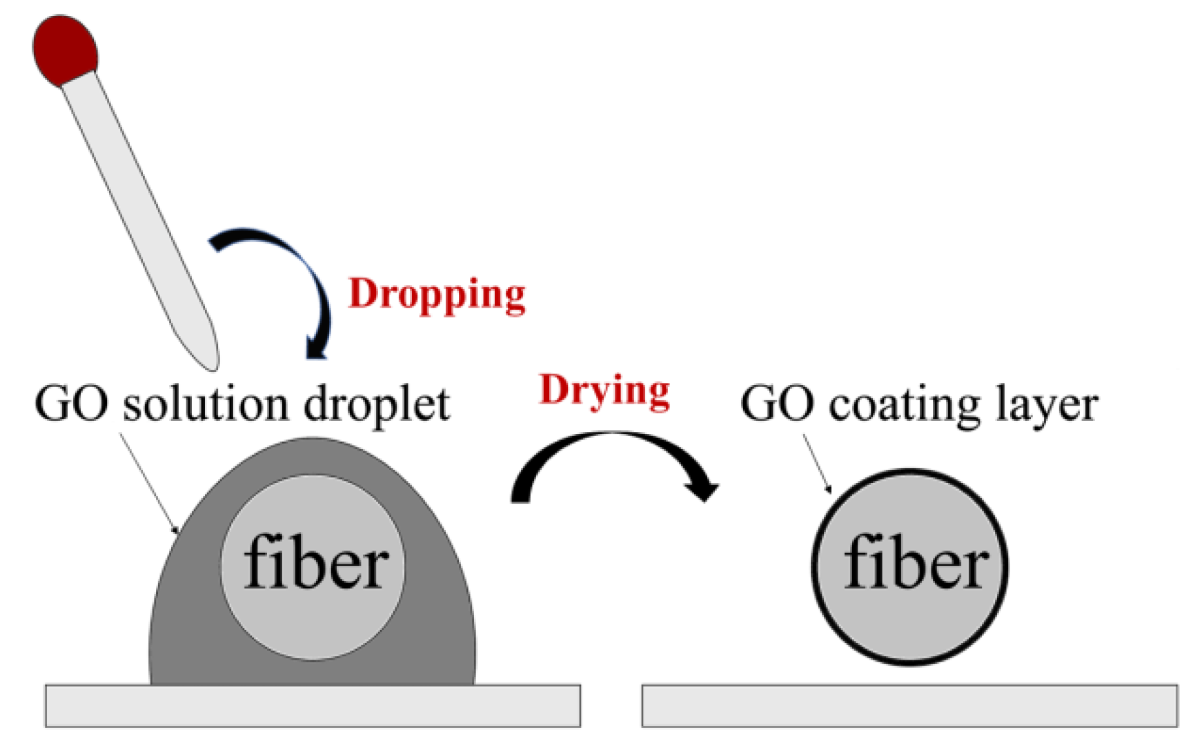
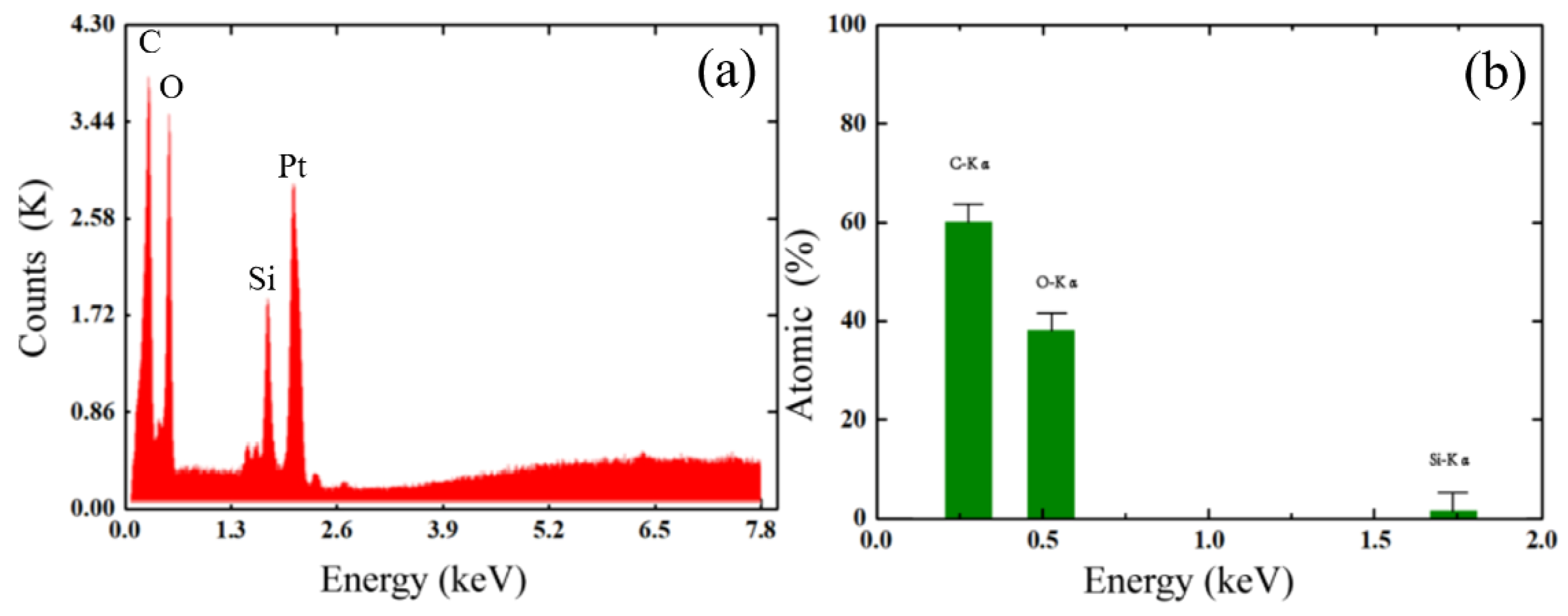
3.2. Preparation and Coating of Graphene Oxide

The process of coating GO onto the tapered-TCF is shown in Figure 4. First, a 0.08 mg/mL GO dispersion (XF020, Nanjing XFNANO Materials Tech. Co., Ltd., Nanjing, China) was centrifuged at 10,000 RPM for 15 min to create GO sheets with a size larger than 500 nm. Second, the fiber was cleaned with alcohol several times, and the sensing area was immersed in a sufficient-sized droplet of GO dispersion and was naturally evaporated for 24 h at temperature of 25 °C. As a result, GO adhered to the surface of the fiber, seen in the SEM image (Figure 5). We observe that the GO layer is uniformly attached to the surface of the tapered-TCF and a large number of undulating folds are formed simultaneously. The undulating folds increase the effective surface area of the GO exposed to the gas, which is advantageous for absorption. It should be noted that the thickness of the GO film can be adjusted by controlling the concentration of the GO solution and the immersion time. For comparison, we measured the transmission spectra of the sensor with and without GO (Figure 6). There are no obvious changes except for the contrast, and the GO coating has not affected the interference properties of the sensor.
To further determine the elemental composition of the GO coating material on the fiber, we performed an energy dispersive spectroscopy (EDS) analysis, as shown in Figure 7a. The coating material mainly contains the elements C, O, Si and Pt; Si is a component of the optical fiber, and Pt was sprayed on to obtain the EDS image. Figure 7b shows the atomic composition of each major element of the coating material; the specific gravity of the three elements C, O and Si are 59.92, 38.17 and 1.92%, respectively, and the GO coating is without significant impurities. It should be noted that the functional group in the GO contains hydrogen, which does not appear in this EDS elemental analysis.

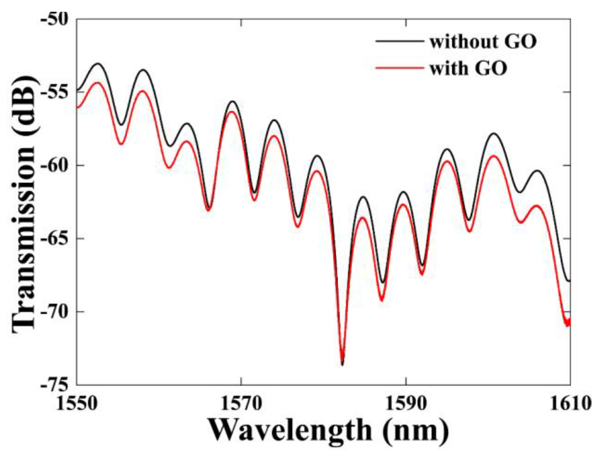
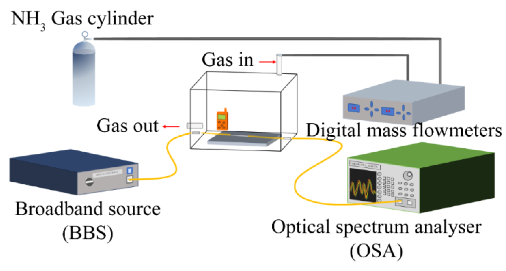
4. Experimental Results and Discussion

The performance of this sensor was investigated using the experimental setup shown in Figure 8. The sensor was placed in a sealed gas chamber. A broadband light source (BBS) (ASE-C+L module, HOYATEK, Shenzhen, China) was used to illuminate the interferometer. The output spectrum was acquired by an optical spectrum analyzer (OSA) (AQ6370B, YOKOGAWA, Tokyo, Japan). The gas chamber was constructed of pure silica and kept sealed; the inlet and outlet ports were gas-tight switched valves. Before injecting ammonia gas, the air chamber was connected with the ventilation unit for one hour to discharge as much water vapor and other impurities as possible from the air chamber and the pipeline. The outlet valve was then closed to ensure that the air in the gas chamber was no longer disturbed by external ambient air. At this time, there was only air in the gas chamber, and the output spectrum was recorded as an initial reference for the NH3 concentration 0 ppm. Subsequently, the mixture of NH3 and N2 in a volume ratio of 5:95 was gradually injected into the gas chamber to mix with the air to get different NH3 concentrations. The main component of air retained in the air chamber is nitrogen gas, and only nitrogen gas follows a trace amount of ammonia gas into the gas chamber. Further, the molar amount of the injected gas is also small due to the low NH3 concentration. So, it can be considered that the change of the transmission spectrum in the experiments is caused by the concentration adjustment of the ammonia gas.
In the experiments, the ammonia gas concentration increased from 0 to 151 ppm. Figure 9 shows the transmission spectra for different concentrations of NH3. The ammonia gas mass flow rate into the chamber was precisely controlled by a digital mass flow meter and the gas concentration was monitored in real time using a chemical ammonia gas sensor placed in the chamber to achieve different ammonia gas concentrations. In order to obtain good observation results, we selected the resonant dip near 1587 nm in Figure 6 as the observation point, and recorded the output spectrum for different ammonia gas concentrations. After the end of the experiment, the gas was discharged from the gas chamber. All experiments were carried out at a temperature of 25 °C and the pressure inside the gas chamber was the same as the atmospheric pressure.
From Figure 9, we can see that the wavelength of the resonant dip shifts to shorter wavelengths as the concentration of NH3 increases through the range 0–151 ppm. There are many polar functional groups in GO, such as hydroxyl and carboxyl groups, and epoxy functional groups, which can promote the adsorption of NH3 on the GO. GO absorbs NH3 and interacts with NH3, and the charge transfer from NH3 to GO is very significant due to the formation of surface hydrogen bonds [37,39]. The above process will result in a decrease in the dielectric constant and conductivity of GO, so the refractive index of GO will increase because it is inverse proportion to the dielectric constant and conductivity, as shown in Figure 10, and then the effective refractive index of the cladding mode will increase due to the effect by the refractive index change of the GO. As a result, the wavelength of the resonant dip will shift to short wavelength because the effective refractive index difference between the core mode and the cladding mode decreases. In the experiment, the absorption effect will increase when the ammonia gas concentration increases. The phase difference between the core mode and the cladding mode will decrease further, so the wavelength of the resonant dip will continually shift to short wavelength. On the contrary, the wavelength of the resonant dip will shift to near the original position when NH3 is desorbed from the GO.
The relationship between wavelength shift and ammonia gas concentration is shown in Figure 11. The linear fitting results indicate a sensitivity of 4.97 pm/ppm with linear fit coefficient of 98.9% can be achieved in the range of 0–151 ppm ammonia gas concentration.
In order to investigate the reproducibility and reversibility of the proposed sensor, we repeatedly injected and extracted the ammonia gas with a concentration of 200 ppm into the gas chamber at a temperature of 25 °C. The transmission spectrum was recorded at intervals of 50 s to determine the dynamic behavior of the gas sensor. After the transmission spectrum reached a stable state, indicated when the wavelength of the interferometer minimum was no longer shifting, the next fill or discharge of ammonia gas took place. We recorded the wavelength shift of the resonant dip during two periods of ammonia gas fill and discharge, as shown in Figure 12. The results indicate that the dynamic response rising time (tr) and falling time (tf) of the sensor are about 5 and 7.5 min for the two periods, respectively. These repeated cycles of exposure to 0 and 200 ppm of NH3 gas demonstrate that the rising and falling time are not very fast, but the sensor exhibits good reversibility. The response and recovery time of the sensor are determined by the thickness of the GO layer, the diameter of the tapered fiber and the rate of ammonia gas mixing in the chamber on injection or expulsion.
Humidity is a common environmental variable which can also cause transmission spectrum changes, so we have tested the humidity response characteristics of the sensor. The sensor was put into a constant temperature and humidity chamber (J-TOPH-22-B, Jiexin Testing Equipment Co., Ltd., Dongguan, China) with a relative humidity range from 35% to 70%, which basically covers the range of common relative humidity changes. The output transmission spectrum at different relative humidity with the ammonia gas concentration of 0 ppm is shown in Figure 13a. We can see that the wavelength and intensity of the resonant dip will vary when the relative humidity increases from 35% to 70%. GO films are highly hygroscopic due to the presence of oxygen-containing groups on the surface and edges of GO [18,34]. When the relative humidity of the environment increases, the GO film absorbs more water molecules. The water molecules will adhere to the surface of the GO or fill the GO layer, which causes the GO film to swell [25]. Thus, the refractive index of the GO film will decrease as the water molecules increase, and the refractive index difference between the GO film and the fiber cladding will be smaller. When light in the fiber passes through the cladding and reaches the interface between the cladding and the GO film, part of the light is reflected at the interface, and evanescent wave leakage is suppressed and reduced. As a result, the contrast ratio of the transmission spectrum decreases as the relative humidity increases.
We select the Dip A and B to observe the wavelength variation, shown as in Figure 13b. The wavelength fluctuation of 0.23 and 0.14 nm for Dip A and B is not obvious. Furthermore, the relative humidity in the gas response experiments varies hardly. So, we think that the response of the sensor for ammonia gas is obvious.
The performances of the fiber sensors for ammonia gas measurement is listed in Table 1. It can be seen that that the proposed sensor has a high sensitivity in a wide range of RH.

5. Conclusions

This paper proposes a GO-coated Mach-Zehnder fiber interferometer for measurement of ammonia gas concentration. When the GO film absorbs ammonia gas, the change in the refractive index of the film affects the effective refractive index of the cladding mode and the phase of light in the fiber. As a result, the wavelength of the dip in the interferometer response is shifted. The results show that a sensitivity of 4.97 pm/ppm with the linear fit coefficient (R2) of 98.9% can be achieved in the ammonia gas concentration range of 0–151 ppm. The rising time and falling time of the sensor are about 5 and 7.5 min, respectively. The sensitivity can be improved with a thick GO film, but the response time will also increase simultaneously. It has good linear response and stable room temperature recovery. The proposed sensor has the advantages of simple manufacture, small volume, passive design and can be used for on-line monitoring of ammonia gas in a room temperature atmosphere.

Author Contributions

Conceptualization, X.F.; methodology, S.D.; software, X.F.; validation, F.W. and C.T.; formal analysis, X.F.; investigation, X.F.; resources, H.M.; data curation, F.W.; writing-original draft preparation, X.F.; writing-review and editing, F.W. and H.M.; visualization, C.T. and Z.W.; supervision, H.M.; funding acquisition, Z.W. and H.M. All authors have read and agreed to the published version of the manuscript.

Funding

This work was supported by the National Natural Science Foundation of China (Grant Nos. 11674109 and 61774062), the Natural Science Foundation of Guangdong Province of China (Grant No. 2016A030313443) and the Science and Technology Planning Project of Guangdong Province of China (Grant No. 2017A020219007).

Institutional Review Board Statement

Not applicable.

Informed Consent Statement

Not applicable.

Data Availability Statement

The data that supports the findings of this study are available from the authors on reasonable request, see author contributions for specific data sets.

Conflicts of Interest

The authors declare no conflict of interest.

References

  1. Timmer, B.H.; Olthuis, W.; Albert, V.D.B. Ammonia sensors and their applications—A review. Sens. Actuator B Chem. 2015, 107, 666–677. [Google Scholar] [CrossRef]
  2. Liu, A.; Lv, S.Y.; Jiang, L.; Liu, F.M.; Zhao, L.J.; Wang, J.; Hu, X.L.; Yang, Z.J.; He, J.M.; Wang, C.G.; et al. The gas sensor utilizing polyaniline/MoS2 nanosheets/SnO2 nanotubes for the room temperature detection of ammonia. Sens. Actuator B Chem. 2021, 332, 129444. [Google Scholar] [CrossRef]
  3. Li, Z.; Yi, J.X. Drastically enhanced ammonia sensing of Pt/ZnO ordered porous ultra-thin films. Sens. Actuator B Chem. 2020, 317, 128217. [Google Scholar] [CrossRef]
  4. Alexander, F.S.; Liu, X.M.; Trevor, L.W.; Fu, T.D.; Todd, E.; Juan, M.J.; Derek, R.L.; Yao, J. Bioelectronic protein nanowire sensors for ammonia detection. Nano Res. 2020, 13, 1479–1484. [Google Scholar] [CrossRef]
  5. Wu, T.Y.; Lv, D.W.; Shen, W.F.; Song, W.J.; Tan, R.Q. Trace-level ammonia detection at room temperature based on porous flexible polyaniline/polyvinylidene fluoride sensing film with carbon nanotube additives. Sens. Actuator B Chem. 2020, 316, 128198. [Google Scholar] [CrossRef]
  6. Cao, W.Q.; Duan, Y.X. Optical fiber-based evanescent ammonia sensor. Sens. Actuator B Chem. 2005, 110, 252–259. [Google Scholar] [CrossRef]
  7. Mishra, S.K.; Kumari, D.; Gupta, B.D. Surface plasmon resonance based fiber optic ammonia gas sensor using ITO and polyaniline. Sens. Actuator B Chem. 2005, 171, 976–983. [Google Scholar] [CrossRef]
  8. Zhang, A.Q.; Wu, Y.; Yao, B.C.; Gong, Y. Optimization study on graphene-coated microfiber Bragg grating structures for ammonia gas sensing. Photonic. Sens. 2015, 5, 84–90. [Google Scholar] [CrossRef] [Green Version]
  9. Fu, H.W.; Zhang, J.L.; Ding, J.J.; Wang, Q.Q.; Li, H.D.; Shao, M.Y.; Liu, G.Q.; Liu, P.; Zhang, M.; Zhu, Y.; et al. Ultra sensitive NH3 gas detection using microfiber Bragg grating. Opt. Commun. 2018, 427, 331–334. [Google Scholar] [CrossRef]
  10. Zhou, Q.; Kritz, D.; Bonnell, L.; Sigel, G.H.J. Porous plastic optical fiber sensor for ammonia measurement. Appl. Opt. 1989, 28, 2022–2025. [Google Scholar] [CrossRef]
  11. Huang, X.Y.; Li, X.M.; Yang, J.C.; Tao, C.Y.; Guo, X.G.; Bao, H.B.Y.; Yin, J.; Chen, H.F.; Zhu, Y.H. An in-line Mach-Zehnder interferometer using thin-core fiber for ammonia gas sensing with high sensitivity. Sci. Rep. 2017, 7, 44994. [Google Scholar] [CrossRef] [Green Version]
  12. Zheng, S.J.; Ghandehari, M.; Ou, J.P. Photonic crystal fiber long-period grating absorption gas sensor based on a tunable erbium-doped fiber ring laser. Sens. Actuator B Chem. 2016, 223, 324–332. [Google Scholar] [CrossRef]
  13. Khalaf, A.L.; Mohamad, F.S.; Rahman, N.A.; Lim, H.N.; Paiman, S.; Yusof, N.A.; Mahdi, M.A.; Yaacob, M.H. Room temperature ammonia sensor using side-polished optical fiber coated with graphene/polyaniline nanocomposite. Opt. Mater. Express 2017, 7, 1858–1870. [Google Scholar] [CrossRef]
  14. Raj, D.R.; Prasanth, S.T.; Vineeshkumar, V.; Sudarsanakumar, C. Ammonia sensing properties of tapered plastic optical fiber coated with silver nanoparticles/PVP/PVA hybrid. Opt. Commun. 2015, 340, 86–92. [Google Scholar] [CrossRef]
  15. Pathak, A.; Mishra, S.K.; Gupta, B.D. Fiber-optic ammonia sensor using Ag/SnO2 thin films: Optimization of thickness of SnO2 film using electric field distribution and reaction factor. Appl. Optics 2017, 54, 8712–8721. [Google Scholar] [CrossRef]
  16. Guo, H.Q.; Tao, S.Q. Silver nanoparticles doped silica nanocomposites coated on an optical fiber for ammonia sensing. Sens. Actuator B Chem. 2007, 123, 578–582. [Google Scholar] [CrossRef]
  17. Sun, L.; Semenova, Y.; Wu, Q.D.; Liu, J.; Yuan, J.H.; Ma, T.; Sang, X.Z.; Yan, B.B.; Wang, K.R.; Yu, C.X.; et al. High sensitivity ammonia gas sensor based on a silica-gel-coated microfiber coupler. J. Lightwave Technol. 2017, 35, 2864–2870. [Google Scholar] [CrossRef] [Green Version]
  18. Zhu, Y.; Fu, H.W.; Ding, J.J.; Li, H.D.; Zhang, M.; Zhang, J.L.; Liu, Y.G. Fabrication of three-dimensional zinc oxide nanoflowers for high-sensitivity fiber-optic ammonia gas sensors. Appl. Opt. 2018, 57, 7924–7930. [Google Scholar] [CrossRef]
  19. Shrivastav, A.M.; Sharma, G.; Rathore, A.S.; Jha, R. Hypersensitive and selective interferometric nose for ultratrace ammonia detection with fast response utilizing PANI@SnO2 Nanocomposite. ACS Photonics 2018, 5, 4402–4412. [Google Scholar] [CrossRef]
  20. Yao, B.; Wu, Y.; Cheng, Y.; Zhang, A.; Gong, Y.; Rao, Y.J.; Wang, Z.; Chen, Y. All-optical Mach-Zehnder interferometric NH3 gas sensor based on graphene/microfiber hybrid waveguide. Sens. Actuator B Chem. 2014, 194, 142–148. [Google Scholar] [CrossRef]
  21. Wu, Y.; Yao, B.C.; Zhang, A.Q.; Rao, Y.J.; Wang, Z.G.; Cheng, Y.; Gong, Y.; Zhang, W.L.; Chen, Y.F.; Chiang, K.S. Graphene-coated microfiber Bragg grating for high-sensitivity gas sensing. Opt. Lett. 2014, 39, 1235–1237. [Google Scholar] [CrossRef]
  22. Yu, C.B.; Wu, Y.; Liu, X.L.; Fu, F.; Gong, Y.; Rao, Y.J.; Chen, Y.F. Miniature fiber-optic NH3 gas sensor based on Pt nanoparticle-incorporated graphene oxide. Sens. Actuator B Chem. 2017, 244, 107–113. [Google Scholar] [CrossRef]
  23. Fu, H.W.; Jiang, Y.H.; Ding, J.J.; Zhang, J.L.; Zhang, M.; Zhu, Y.; Li, H.D. Zinc oxide nanoparticle incorporated graphene oxide as sensing coating for interferometric optical microfiber for ammonia gas detection. Sens. Actuator B Chem. 2018, 254, 239–247. [Google Scholar] [CrossRef]
  24. Deng, S.Y.; Meng, H.Y.; Wang, X.J.; Fan, X.F.; Wang, Q.Z.; Zhou, M.Q.; Guo, X.; Wei, Z.C.; Wang, F.Q.; Tan, C.H.; et al. Graphene oxide-film-coated splitting ratio-adjustable Mach-Zehnder interferometer for relative humidity sensing. Opt. Express 2019, 27, 9232–9240. [Google Scholar] [CrossRef]
  25. Wang, Y.Q.; Shen, C.Y.; Lou, W.M.; Shentu, F.Y. Polarization-dependent humidity sensor based on an in-fiber Mach-Zehnder interferometer coated with graphene oxide. Sens. Actuator B Chem. 2016, 234, 503–509. [Google Scholar] [CrossRef]
  26. Lu, P.; Men, L.Q.; Sooley, K.; Chen, Q.Y. Tapered fiber Mach-Zehnder interferometer for simultaneous measurement of refractive index and temperature. Appl. Phys. Lett. 2009, 94, 131110. [Google Scholar] [CrossRef] [Green Version]
  27. Tian, Z.B.; Yam, S.S.H.; Barnes, J.; Bock, W.; Greig, P.; Fraser, J.M.; Loock, H.P.; Oleschuk, R.D. Refractive index sensing with Mach-Zehnder interferometer based on concatenating two single-mode fiber tapers. IEEE Photonic. Tech. Lett. 2008, 20, 626–628. [Google Scholar] [CrossRef]
  28. Hao, T.; Chiang, K.S. Graphene-based ammonia-gas sensor using in-fiber Mach-Zehnder interferometer. IEEE Photonic. Tech. Lett. 2017, 29, 2035–2038. [Google Scholar] [CrossRef]
  29. Geim, A.K.; Novoselov, K.S. The rise of graphene. Nat. Mater. 2007, 6, 183–191. [Google Scholar] [CrossRef]
  30. Bolotin, K.I.; Sikes, K.J.; Jiang, Z.; Klima, M.; Fudenberg, G.; Hone, J.; Kim, P.; Stormer, H.L. Ultrahigh electron mobility in suspended graphene. Solid State Commun. 2008, 146, 351–355. [Google Scholar] [CrossRef] [Green Version]
  31. Leenaerts, O.; Partoens, B.; Peeters, F.M. Adsorption of H2O, NH3, CO, NO2, and NO on graphene: A first principles study. Phys. Rev. B 2008, 77, 125416. [Google Scholar] [CrossRef] [Green Version]
  32. Zhu, Y.W.; Murali, S.; Cai, W.W.; Li, X.S.; Suk, J.W.; Potts, J.R.; Ruoff, S.R. Graphene and graphene oxide: Synthesis, properties, and applications. Adv. Mater. 2010, 22, 3906–3924. [Google Scholar] [CrossRef]
  33. Cerveny, S.; Barroso, B.F.; Alegria, A.; Colmenero, J. Dynamics of water intercalated in graphite oxide. J. Phys. Chem. C 2010, 114, 2604–2612. [Google Scholar] [CrossRef]
  34. Morales-Narvaez, E.; Merkoci, A. Graphene oxide as an optical biosensing platform. Adv. Mater. 2012, 24, 3298–3308. [Google Scholar] [CrossRef]
  35. Stankovich, S.; Dikin, D.A.; Dommett, G.H.B.; Kohlhaas, K.M.; Zimney, E.J.; Stach, E.A.; Piner, R.D.; Nguyen, S.T.; Ruoff, R.S. Graphene-based composite materials. Nature 2006, 442, 282–286. [Google Scholar] [CrossRef] [PubMed]
  36. Dreyer, D.R.; Park, S.; Bielawski, C.W.; Ruoff, R.S. The chemistry of graphene oxide. Chem. Soc. Rev. 2010, 39, 228–240. [Google Scholar] [CrossRef]
  37. Peng, Y.; Li, J.H. Ammonia adsorption on graphene and graphene oxide: A first-principles study. Front. Environ. Sci. Eng. 2013, 7, 403–411. [Google Scholar] [CrossRef]
  38. Girei, S.H.; Alkhabet, M.M.; Kamil, Y.M.; Lim, H.N.; Mahdi, M.A.; Yaacob, M.H. Wavelength dependent graphene oxide-based optical microfiber sensor for ammonia gas. Sensors 2021, 21, 556. [Google Scholar] [CrossRef]
  39. Tang, S.; Cao, Z. Adsorption and dissociation of ammonia on graphene oxides: A first-principles study. J. Phys. Chem. C 2012, 116, 8778–8791. [Google Scholar] [CrossRef]
  40. Schedin, F.; Geim, A.K.; Morozov, S.V.; Hill, E.W.; Blake, P.; Katsnelson, M.I.; Novoselov, K.S. Detection of individual gas molecules adsorbed on graphene. Nat. Mater. 2007, 6, 652–655. [Google Scholar] [CrossRef]
  41. Wu, Y.; Yao, B.C.; Cheng, Y.; Rao, Y.J.; Gong, Y.; Zhang, W.L.; Wang, Z.G.; Chen, Y.F. Hybrid graphene-microfiber waveguide for chemical gas sensing. IEEE J. Sel. Top. Quantum Electron. 2013, 20, 49–54. [Google Scholar] [CrossRef]
  42. Wang, H.H.; Meng, H.Y.; Xiong, R.; Wang, Q.H.; Huang, B.; Zhang, X.; Yu, W.; Tan, C.H.; Huang, X.G. Simultaneous measurement of refractive index and temperature based on asymmetric structures modal interference. Opt. Commun. 2016, 364, 191–194. [Google Scholar] [CrossRef]
  43. Nguyen, L.V.; Hwang, D.; Moon, S.; Moon, D.S.; Chung, Y.J. High temperature fiber sensor with high sensitivity based on core diameter mismatch. Opt. Express 2008, 16, 11369–11375. [Google Scholar] [CrossRef] [PubMed]
  44. Choi, H.Y.; Kim, M.J.; Lee, B.H. All-fiber Mach-Zehnder type interferometers formed in photonic crystal fiber. Opt. Express 2007, 15, 5711–5720. [Google Scholar] [CrossRef] [PubMed]
Figure 1. (a) Schematic of the proposed MZI with a multimode-fiber-thin core-fiber-multimode-fiber (MMF-TCF-MMF) structure. (b) Simulated result of the mode field distribution.
Sensors 21 03886 g001
Figure 2. (a) Transmission spectrum of the sensor with different TCF lengths (L = 30 mm, L = 50 mm). (b) Spatial frequency of fiber fusion based MZI sensor with different lengths.
Sensors 21 03886 g002
Figure 3. (a) SEM image of the tapered-TCF. (b) Transmission spectrum of the MZI sensor with and without tapering.
Sensors 21 03886 g003
Figure 4. Schematic of coating graphene oxide onto the fiber.
Sensors 21 03886 g004
Figure 5. SEM image of the tapered-TCF after coating with GO. Resolution: (a) 50 μm, (b) 5 μm.
Sensors 21 03886 g005
Figure 6. Transmission spectrum before and after coating with graphene oxide.
Sensors 21 03886 g006
Figure 7. (a) EDS of GO coated on the surface of the tapered-TCF. (b) Atomic percentage of each major element.
Sensors 21 03886 g007
Figure 8. Schematic of gas sensing measurement system.
Sensors 21 03886 g008
Figure 9. Transmission spectrum of the sensor for ammonia gas concentration from 0 to 151 ppm at temperature of 25 °C.
Sensors 21 03886 g009
Figure 10. Schematic diagram of NH3 sensing mechanism ammonia of the sensor coated GO.
Sensors 21 03886 g010
Figure 11. The wavelength shift as a function of ammonia gas concentration from 0 to 151 ppm.
Sensors 21 03886 g011
Figure 12. Dynamic responses of the sensor at the ammonia gas concentration of 200 ppm.
Sensors 21 03886 g012
Figure 13. (a) Transmission spectrum of the sensor at the relative humidity from 35% to 70%. (b) Wavelength fluctuation of dip A and B at the relative humidity from 35% to 70%.
Sensors 21 03886 g013
Table 1. Performances of optical fiber humidity sensors proposed in different literatures.
Fiber StructureMaterialSensitivityResponse TimeRecovery TimeRangeReference
microfiber hybrid waveguidegraphene~6 pm/ppm~0.5 snone40–360 ppm[20]
microfiber Bragg gratinggraphene4 pm/ppm~10 min~15 min0–100 ppm[21]
MZI with a long-period fiber gratingsgraphene~3 pm/ppm270 snone10–180 ppm[28]
MZIzinc oxide nanoflowers5.75 pm/(μg/L)~50 s~80 s0–5500 μg/L[18]
MZI based PCFPANI@SnO2none7 s2 s0–8 ppb[19]
MZIGO4.97 pm/ppm5 min7.5 min0–151 ppmThis paper
Publisher’s Note: MDPI stays neutral with regard to jurisdictional claims in published maps and institutional affiliations.

