An UWB/Vision Fusion Scheme for Determining Pedestrians’ Indoor Location


Abstract
1. Introduction
2. Methodology
2.1. The UWB Positioning Algorithm
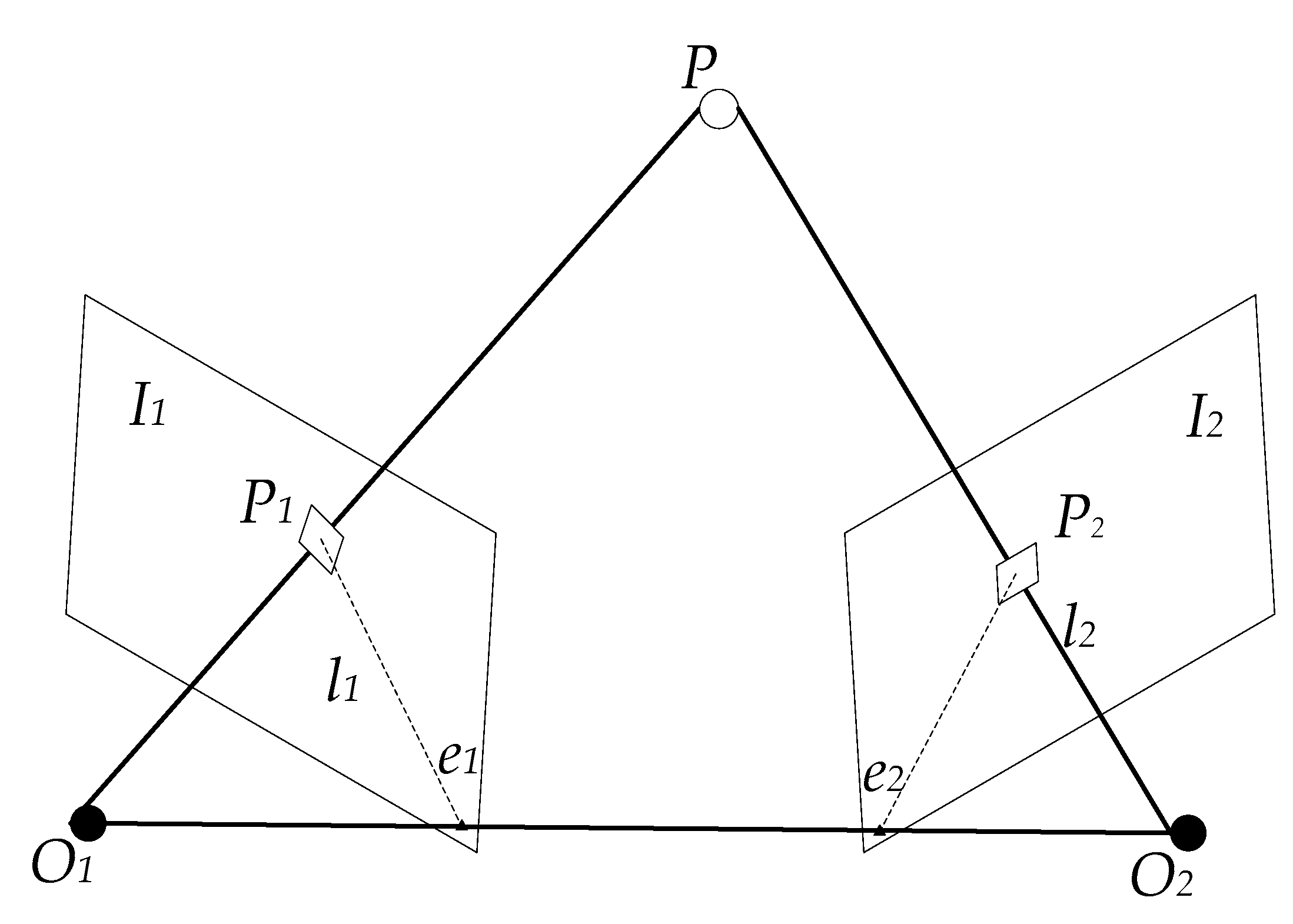
2.2. The Visual Positioning Algorithm
2.3. The Fusion Positioning Algorithm
3. Experimental Verification
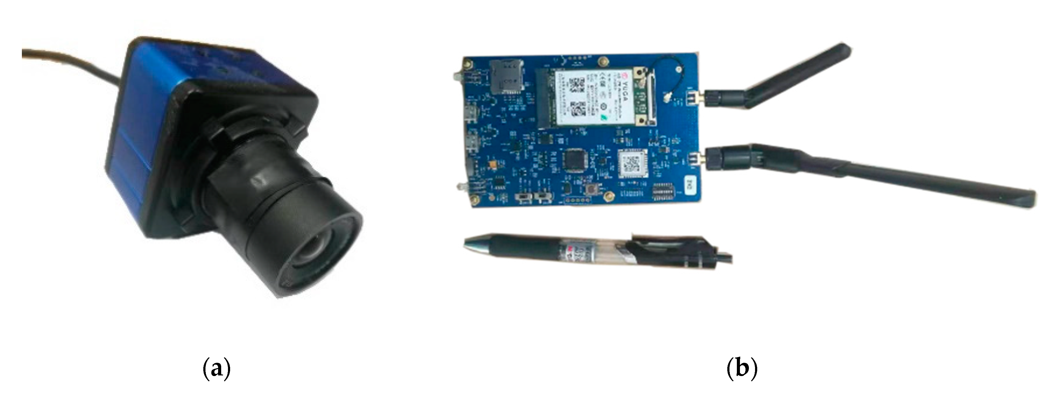
3.1. Introduction of the Experimental Device
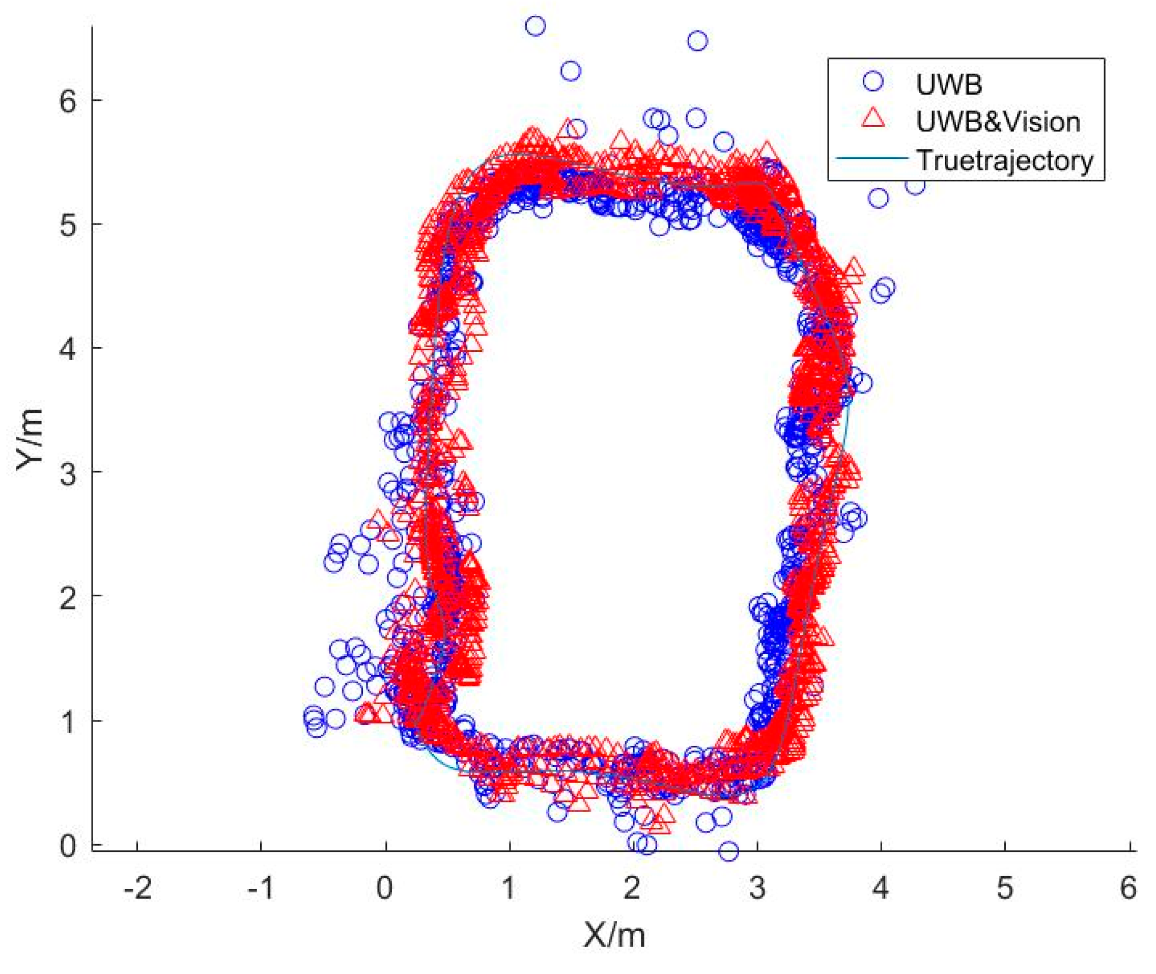
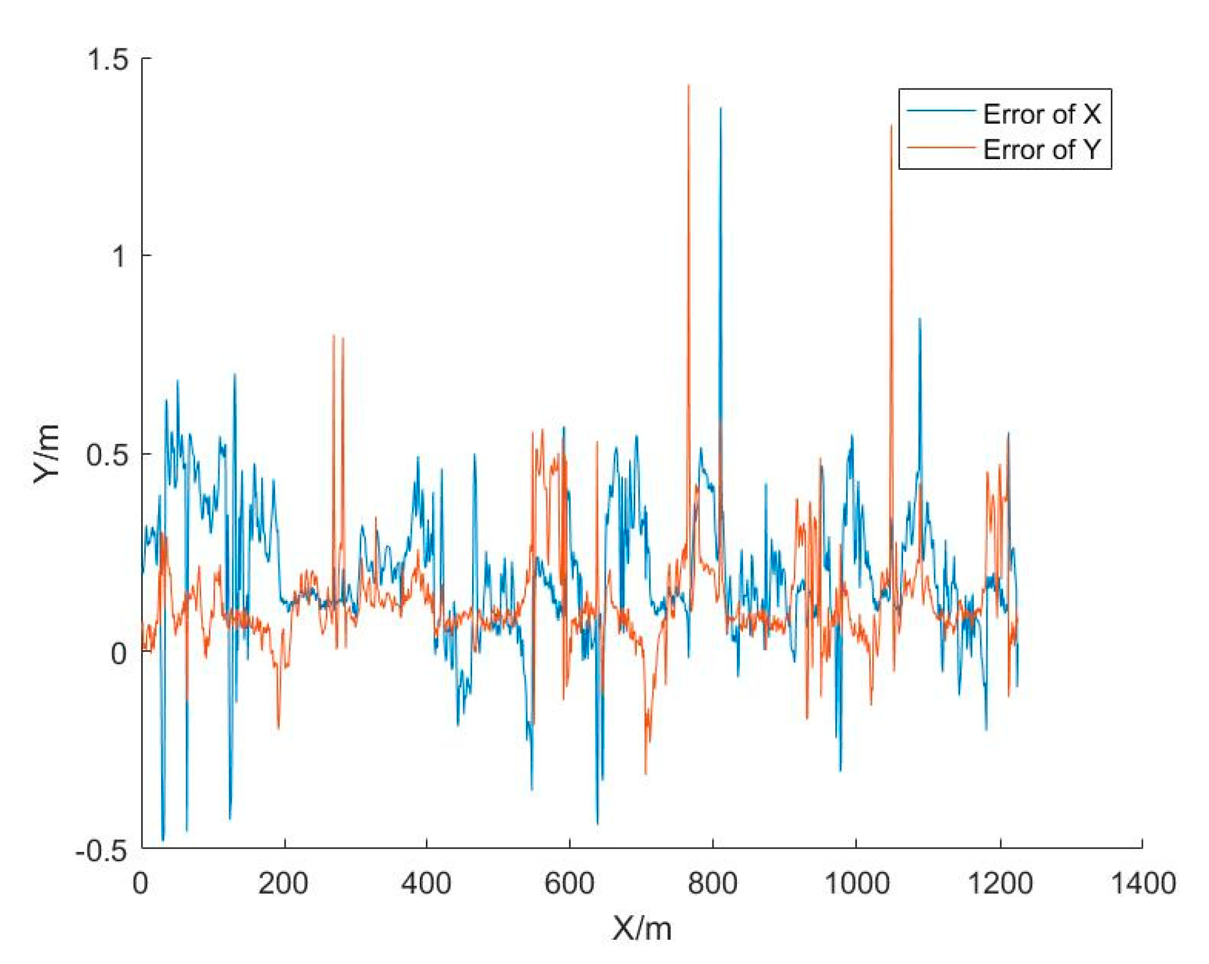
3.2. Experiment 1
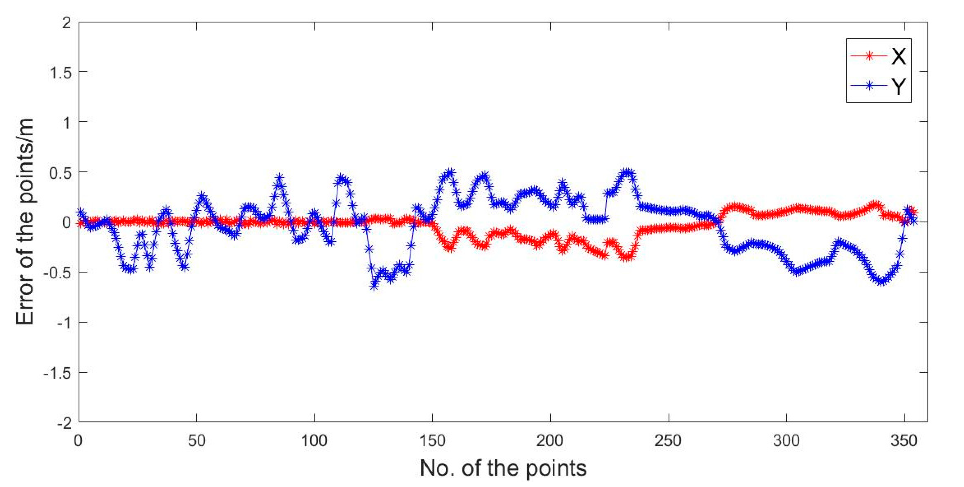
3.3. Experiment 2
4. Conclusions
- (1)
- High relative positioning accuracy can be obtained by using monocular SLAM for indoor positioning, but there is a problem of spatial scale uncertainty and location failures due to factors such as light changes and texture sparsity.
- (2)
- In view of the complex indoor environment, when using pure UWB technology for positioning, there are higher requirements in terms of the number and location of UWB base stations, and it is necessary to measure the coordinates of the base stations in advance.
- (3)
- With the combination of UWB and vision, the scale ambiguity of monocular Slam can be solved. For sparse texture, light brightness variations, and other environmental properties, the vision position method can be repaired using UWB when it fails to locate. The local positioning results of vison are more accurate, which can be used to improve the accuracy of UWB.
- (4)
- For an integrated environment of an indoor corridor and a room, the number of UWB base stations can be reduced. For example, base stations can be set up in corridors for initial positioning or initialization work after positioning failure. This solves the problem of positioning in the room via vision.
- (5)
- There are also challenges in the combination of UWB and Vison, for example, the high time cost and higher frequencies of the initial problem. As the algorithms are coupled in a loose way, the UWB observations cannot be used to directly assist image matching, etc. Therefore, it is necessary to research a tightly coupled algorithm for UWB and vision positioning in the future.
Author Contributions
Funding
Conflicts of Interest
References
- Möller, A.; Kranz, M.; Huitl, R.; Diewald, S.; Roalter, L. A Mobile Indoor Navigation System Interface Adapted to Vision-Based Localization. In Proceedings of the 11th International Conference on Mobile and Ubiquitous Multimedia, Ulm, Germany, 4–6 December 2012. [Google Scholar]
- Sadeghi, H.; Valaee, S.; Shirani, S. A Weighted KNN Epipolar Geometry-Based Approach for Vision-Based Indoor Localization Using Smartphone Cameras. In Proceedings of the 2014 IEEE 8th Sensor Array and Multichannel Signal Processing Workshop (SAM), A Coruna, Spain, 22–25 June 2014. [Google Scholar]
- Scaramuzza, D.; Fraundorfer, F. Visual odometry part I: The first 30 years and fundamentals. IEEE Rob. Autom. Mag. 2011, 18, 80–92. [Google Scholar] [CrossRef]
- Treuillet, S.; Royer, E. Outdoor/indoor vision-based localization for blind pedestrian navigation assistance. Int. J. Image Graph. 2010, 10, 481–496. [Google Scholar] [CrossRef]
- Elloumi, W.; Latoui, A.; Canals, R.; Chetouani, A.; Treuillet, S. Indoor pedestrian localization with a smartphone: A comparison of inertial and vision-based methods. IEEE Sens. J. 2016, 16, 5376–5388. [Google Scholar] [CrossRef]
- Vedadi, F.; Valaee, S. Automatic visual fingerprinting for indoor image-based localization applications. IEEE Trans. Syst. Man Cybern. Syst. 2017, 1–13. [Google Scholar] [CrossRef]
- Liang, J.Z.; Corso, N.; Turner, E.; Zakhor, A. Image Based Localization in Indoor Environments. In Proceedings of the 2013 Fourth International Conference on Computing for Geospatial Research and Application, San Jose, CA, USA, 22–24 July 2013. [Google Scholar]
- Fraundorfer, F.; Scaramuzza, D. Visual odometry part ii: Matching, robustness, optimization, and applications. IEEE Rob. Autom. Mag. 2012, 19, 78–90. [Google Scholar] [CrossRef]
- Mautz, R.; Tilch, S. Survey of Optical Indoor Positioning Systems. In Proceedings of the 2011 International Conference on Indoor Positioning and Indoor Navigation, Guimaraes, Portugal, 21–23 September 2011. [Google Scholar]
- Do, T.; Carrillo-Arce, L.C.; Roumeliotis, S.I. High-speed autonomous quadrotor navigation through visual and inertial paths. Int. J. Rob. Res. 2019, 38, 486–504. [Google Scholar] [CrossRef]
- Zhu, C.; He, M.; Yang, S.; Wu, C.; Liu, B. Survey of monocular visual odometry. Comput. Eng. Appl. 2018, 54, 20–28. [Google Scholar]
- Nützi, G.; Weiss, S.; Scaramuzza, D.; Siegwart, R. Fusion of IMU and vision for absolute scale estimation in monocular SLAM. J. Intell. Rob. Syst. 2011, 61, 287–299. [Google Scholar] [CrossRef]
- Jung, S.-H.; Taylor, C.J. Camera Trajectory Estimation using Inertial Sensor Measurements and Structure from Motion Results. In Proceedings of the 2001 IEEE Computer Society Conference on Computer Vision and Pattern Recognition, Kauai, HI, USA, 8–14 December 2001. [Google Scholar]
- Klein, G.; Murray, D. Parallel Tracking and Mapping for Small AR Workspaces. In Proceedings of the 2007 6th IEEE and ACM International Symposium on Mixed and Augmented Reality, Nara, Japan, 13–16 November 2007. [Google Scholar]
- Yang, L.; Giannakis, G.B. Ultra-wideband communications: An idea whose time has come. IEEE Signal Process Mag. 2004, 21, 26–54. [Google Scholar] [CrossRef]
- Liu, F.; Wang, J.; Zhang, J.; Han, H. An indoor localization method for pedestrians base on combined UWB/PDR/Floor map. Sensors 2019, 19, 2578. [Google Scholar] [CrossRef] [PubMed]
- Liu, F.; Li, X.; Wang, J.; Zhang, J. An adaptive UWB/MEMS-IMU complementary kalman filter for indoor location in NLOS environment. Remote Sens. 2019, 11, 2628. [Google Scholar] [CrossRef]
- Qiao, Z.; Xu, A.; Sui, X.; Hao, Y. An integrated indoor positioning method using ORB-SLAM/UWB. J. Navig. Position. 2018, 6, 29–34. [Google Scholar]
- Tiemann, J.; Ramsey, A.; Wietfeld, C. Enhanced UAV Indoor Navigation through SLAM-Augmented UWB Localization. In Proceedings of the 2018 IEEE International Conference on Communications Workshops, Kansas City, MO, USA, 20–24 May 2018. [Google Scholar]
- Ramirez, B.; Chung, H.; Derhamy, H.; Eliasson, J.; Barca, J.C. Relative Localization with Computer Vision and UWB Range for Flying Robot Formation Control. In Proceedings of the International Conference on Control, Automation, Robotics and Vision, Phuket, Thailand, 13–15 November 2016. [Google Scholar]
- Benini, A.; Mancini, A.; Longhi, S. An IMU/UWB/vision-based extended kalman filter for mini-UAV localization in indoor environment using 802.15.4a wireless sensor network. J. Intell. Rob. Syst. 2013, 70, 461–476. [Google Scholar] [CrossRef]
- Nyqvist, H.E.; Skoglund, M.A.; Hendeby, G.; Gustafsson, F. Pose Estimation Using Monocular Vision and Inertial Sensors Aided with Ultra Wide Band. In Proceedings of the 2015 International Conference on Indoor Positioning and Indoor Navigation (IPIN), Banff, AB, Canada, 13–16 October 2015. [Google Scholar]
- Mur-Artal, R.; Tardos, J.D. ORB-SLAM2: An Open-Source SLAM System for Monocular, Stereo, and RGB-D Cameras. IEEE Tran. Rob. 2017, 1–8. [Google Scholar] [CrossRef]
- Mur-Artal, R.; Montiel, J.M.M.; Tardos, J.D. ORB-SLAM: A versatile and accurate monocular SLAM system. IEEE Tran. Rob. 2015, 31, 1147–1163. [Google Scholar] [CrossRef]
- Zhang, Z. A flexible new technique for camera calibration. IEEE Trans. Pattern Anal. Mach. Intell. 2000, 22, 1330–1334. [Google Scholar] [CrossRef]
- Gao, X.; Zhang, T.; Liu, Y.; Yan, Q. Visual Slam 14 Lectures from Theory to Practice; Publishing House of Electronics Industry: Beijing, China, 2017. [Google Scholar]
- Shin, D.H.; Sung, T.K. Comparisons of error characteristics between TOA and TDOA positioning. IEEE Trans. Aerosp. Electron. Syst. 2002, 38, 307–311. [Google Scholar] [CrossRef]
- Grewal, M.S.; Andrews, A.P. Kalman Filtering: Theory and Practice Using MATLAB; John Wiley & Sons: Hoboken, NY, USA, 2008. [Google Scholar]
- Yuanxi, Y. Kinematic and static filtering for multi-sensor navigation systems. Geomatics Inf. Sci. Wuhan Univ. 2003, 28, 386–388. [Google Scholar]
- Gonzalez, F.T. Visual Inertial Odometry for Mobile Robotics. Available online: http://digital.csic.es/bitstream/10261/155347/1/odometrobot.pdf (accessed on 20 June 2019).
- Hartley, R.; Zisserman, A. Multiple View Geometry in Computer Vision, 2nd ed.; Cambridge University Press: Cambridge, UK, 2000. [Google Scholar]
- Rublee, E.; Rabaud, V.; Konolige, K.; Bradski, G.R. ORB: An Efficient Alternative to SIFT or SURF. In Proceedings of the 2011 International Conference on Computer Vision, Barcelona, Spain, 6–13 November 2011. [Google Scholar]
- Muja, M.; Lowe, D.G. Fast Approximate Nearest Neighbors with Automatic Algorithm Configuration. In Proceedings of the International Conference on Computer Vision Theory and Application, Kyoto, Japan, September 27–October 4 2009. [Google Scholar]
- Lepetit, V.; Moreno-Noguer, F.; Fua, P. EPnP: An accurateo(n) solution to the PnP problem. Int. J. Comput. Vision 2009, 81, 155–166. [Google Scholar] [CrossRef]
- Brown, R.G.; Hwang, P.Y.C. Introduction to Random Signals and Applied Kalman Filtering: With MATLAB Exercises and Solutions, 4th ed.; John Wiley & Sons, Inc.: Hoboken, NY, USA, 2002. [Google Scholar]
- Han, H.; Wang, J.; Liu, F.; Zhang, J.; Yang, D.; Li, B. An emergency seamless positioning technique based on ad hoc UWB networking using robust EKF. Sensors 2019, 19, 3135. [Google Scholar] [CrossRef] [PubMed]


| Performance | Parameter |
|---|---|
| Frame rate (FPS) | 10 |
| Fx (pixels) | 3637.74 |
| Fy (pixels) | 3658.25 |
| Resolution (pixels) | 1920 × 1080 |
| Brightness mode | Auto |
| Performance | Parameter |
|---|---|
| Size | 9 × 12.5 × 0.7 cm |
| Operating voltage | 3–5 V |
| Receiving sensitivity | −118 dBm |
| Ranging accuracy | ≤ 10 cm |
| Line-of-sight ranging distance | Max 880 m |
| Positioning accuracy | ≤ 30 cm |
| Positioning sampling rate | 1–5 Hz |
| Sensor | UWB | UWB/Vision |
|---|---|---|
| RMSE[m] | 0.32 | 0.18 |
| Sensor | UWB | UWB/Vision |
|---|---|---|
| RMSE[m] | 0.30 | 0.17 |
© 2020 by the authors. Licensee MDPI, Basel, Switzerland. This article is an open access article distributed under the terms and conditions of the Creative Commons Attribution (CC BY) license (http://creativecommons.org/licenses/by/4.0/).
Share and Cite
Liu, F.; Zhang, J.; Wang, J.; Han, H.; Yang, D. An UWB/Vision Fusion Scheme for Determining Pedestrians’ Indoor Location. Sensors 2020, 20, 1139. https://doi.org/10.3390/s20041139
Liu F, Zhang J, Wang J, Han H, Yang D. An UWB/Vision Fusion Scheme for Determining Pedestrians’ Indoor Location. Sensors. 2020; 20(4):1139. https://doi.org/10.3390/s20041139
Chicago/Turabian StyleLiu, Fei, Jixian Zhang, Jian Wang, Houzeng Han, and Deng Yang. 2020. "An UWB/Vision Fusion Scheme for Determining Pedestrians’ Indoor Location" Sensors 20, no. 4: 1139. https://doi.org/10.3390/s20041139
APA StyleLiu, F., Zhang, J., Wang, J., Han, H., & Yang, D. (2020). An UWB/Vision Fusion Scheme for Determining Pedestrians’ Indoor Location. Sensors, 20(4), 1139. https://doi.org/10.3390/s20041139