A Dielectric Resonator Antenna with Enhanced Gain and Bandwidth for 5G Applications


Abstract
1. Introduction
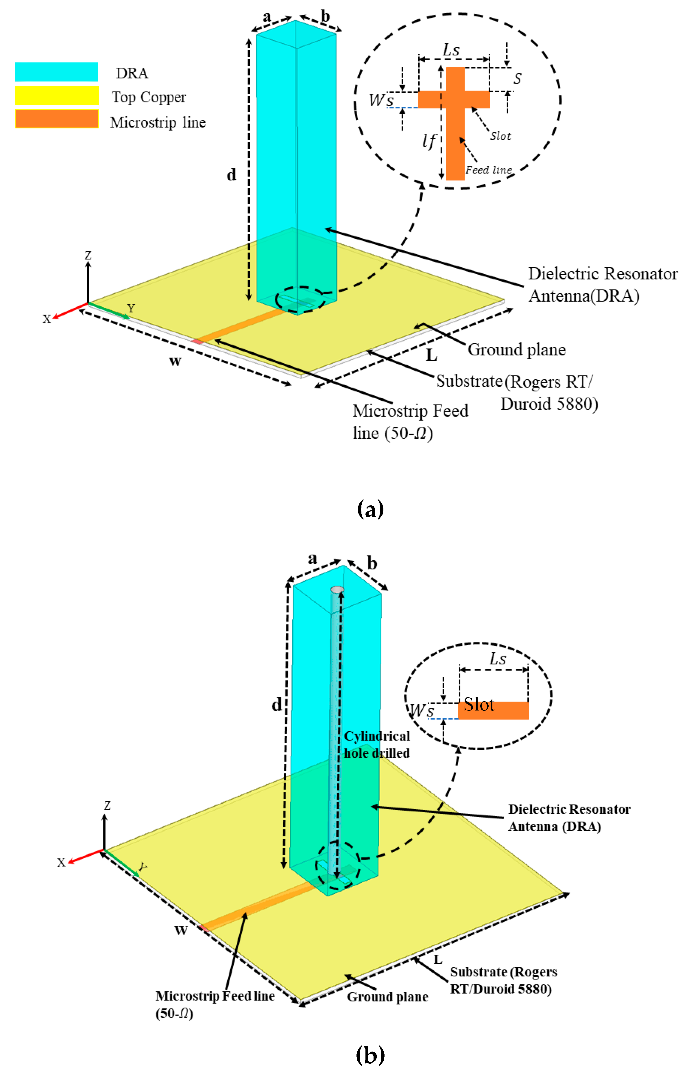
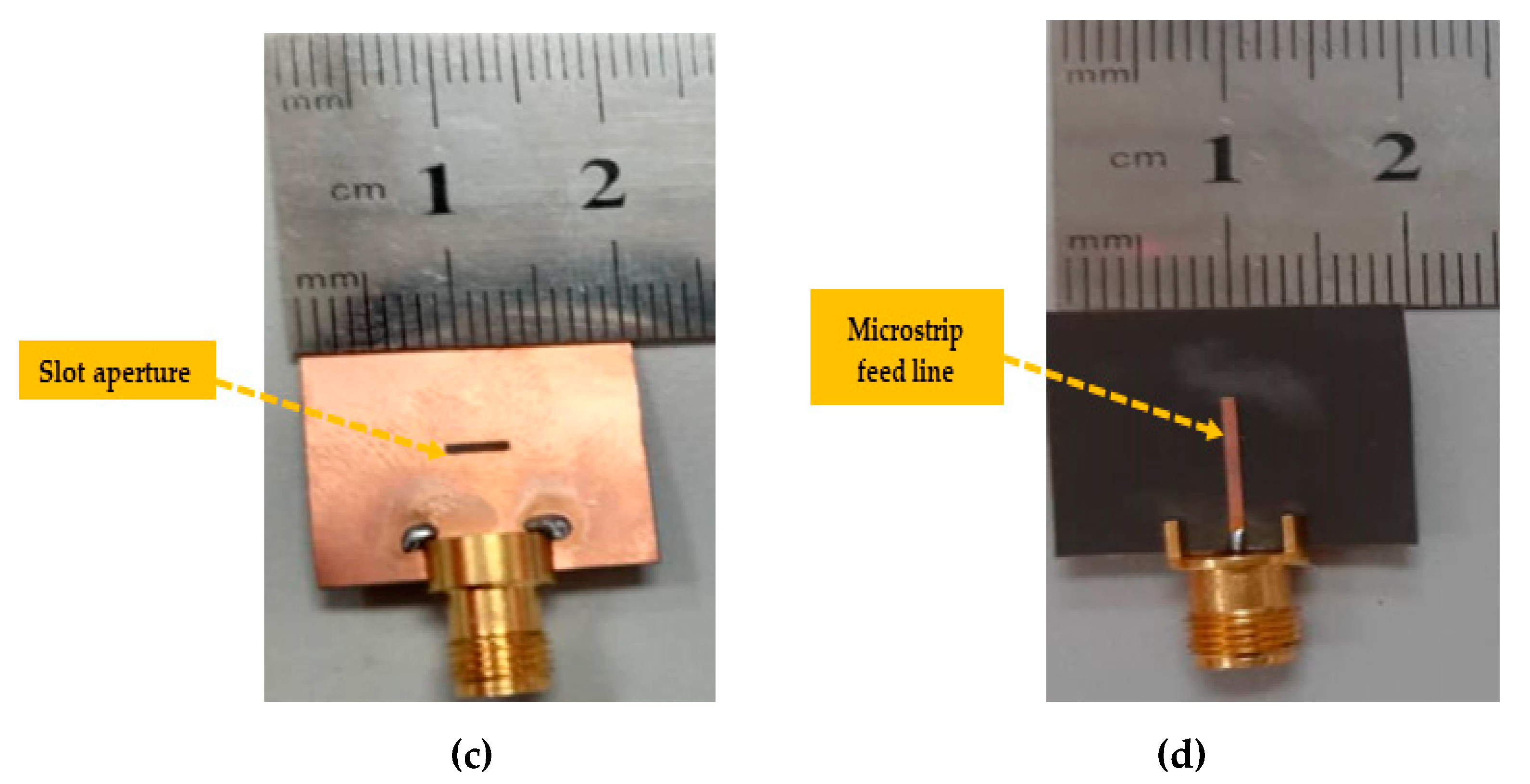
2. Antenna Design and Analysis
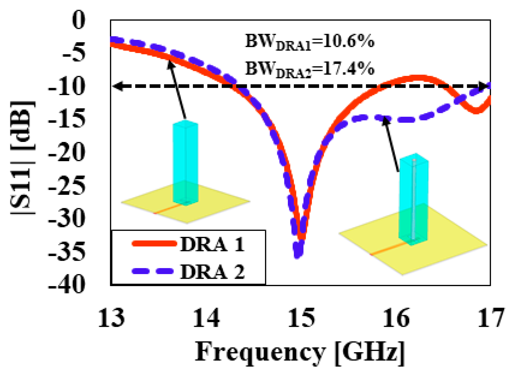
3. Measurement Results and Discussion
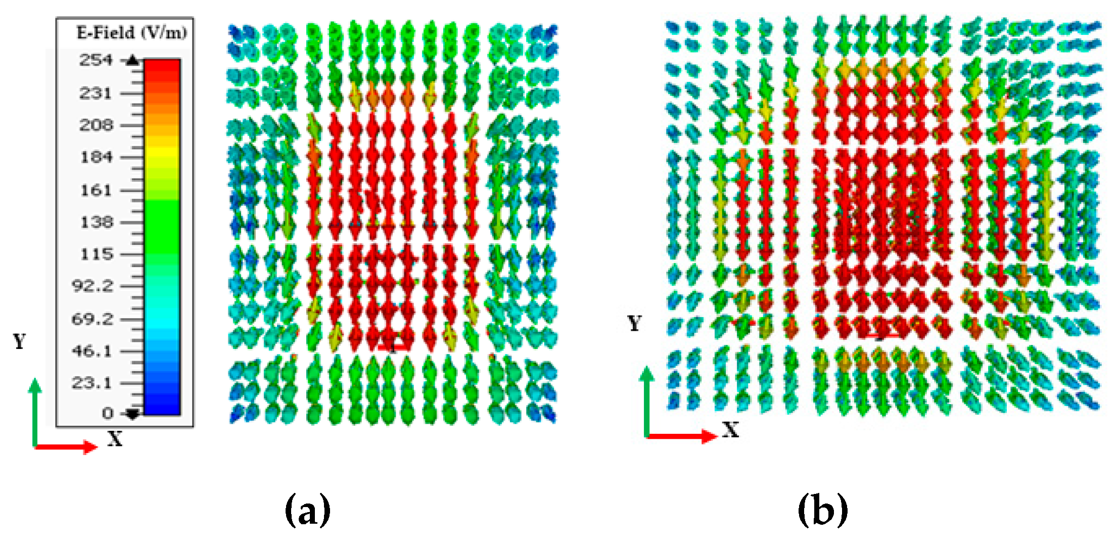
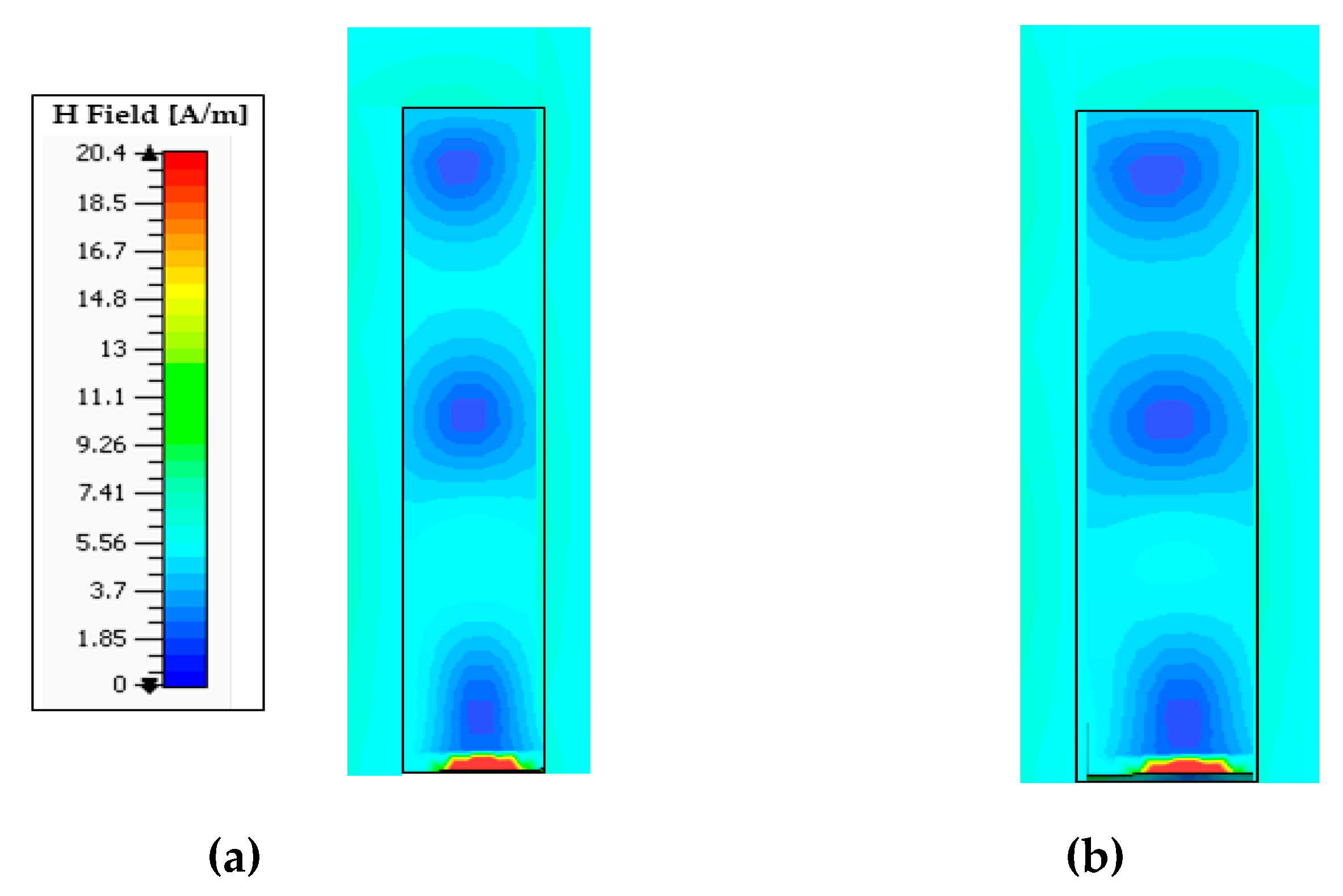
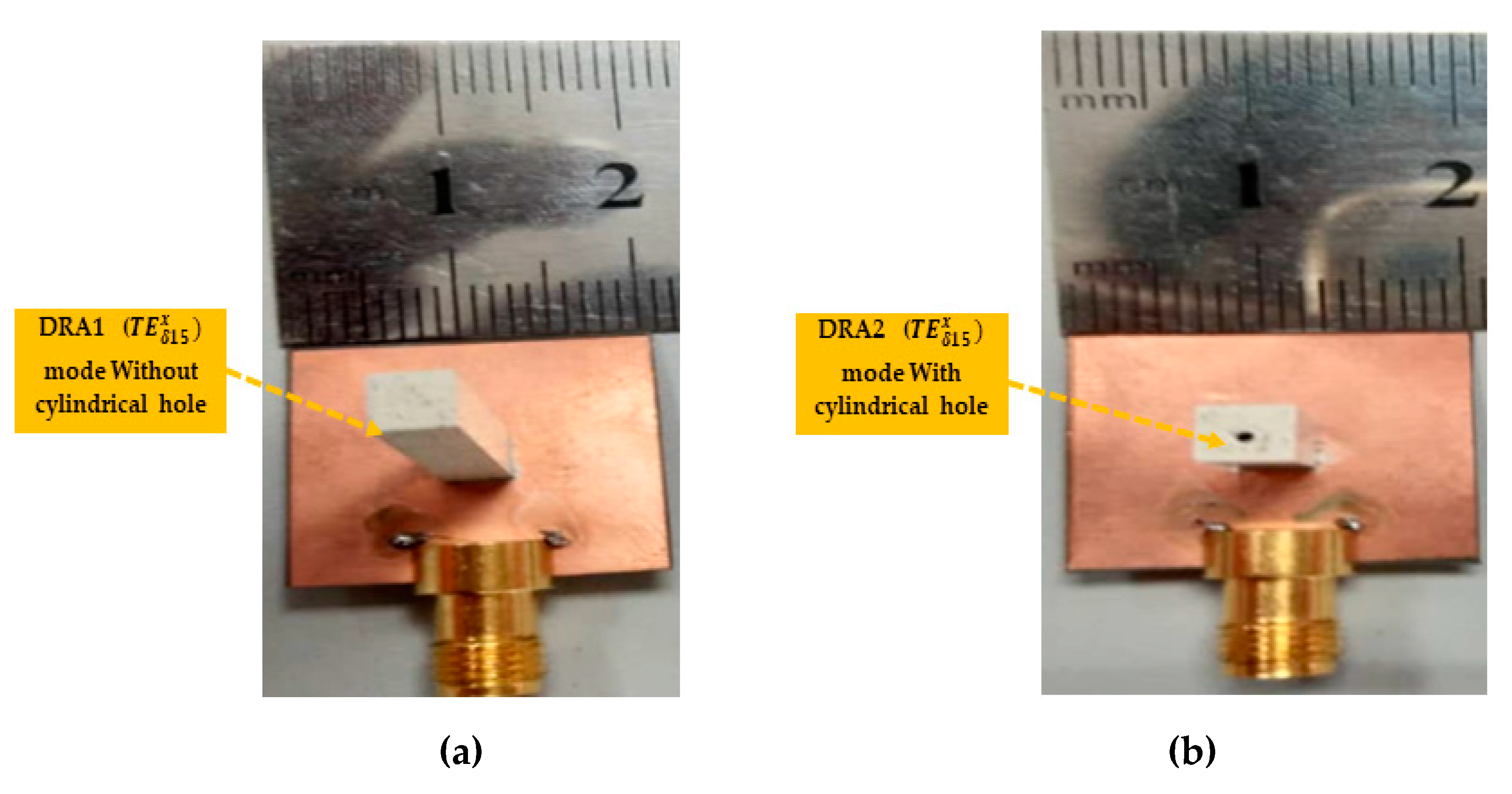
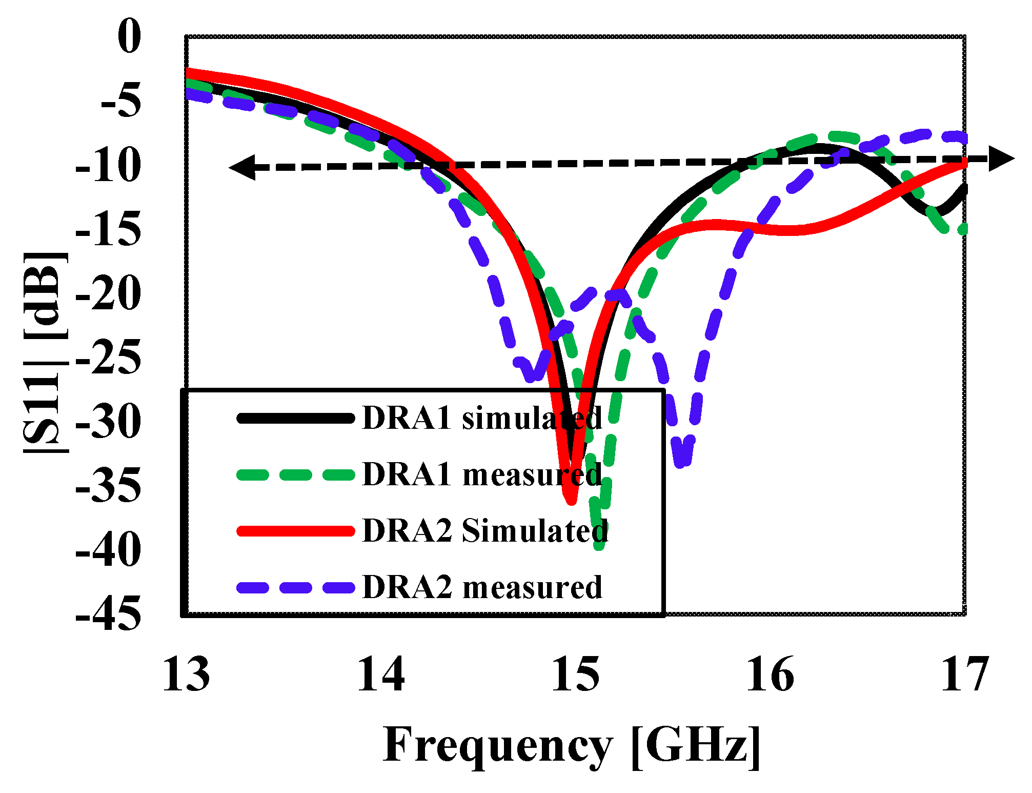
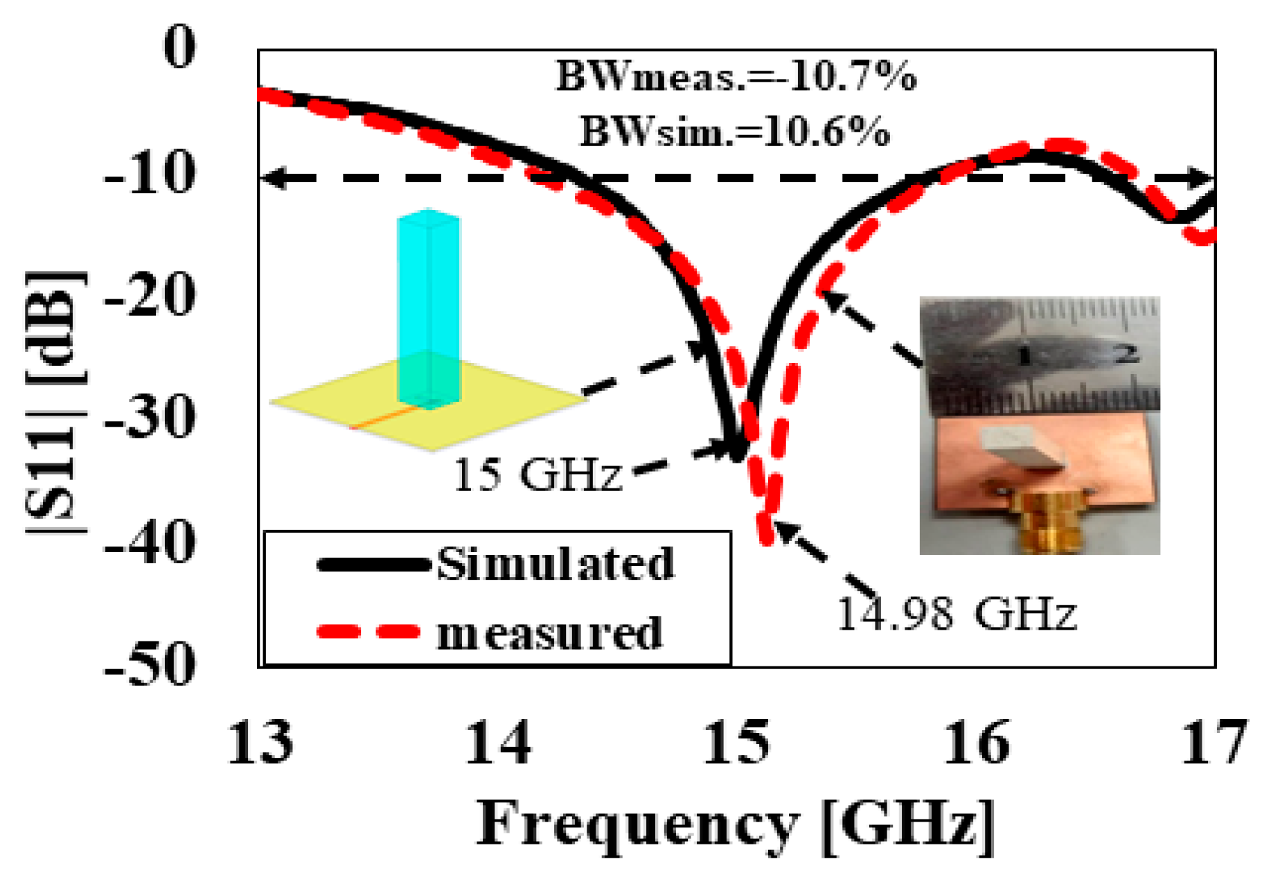
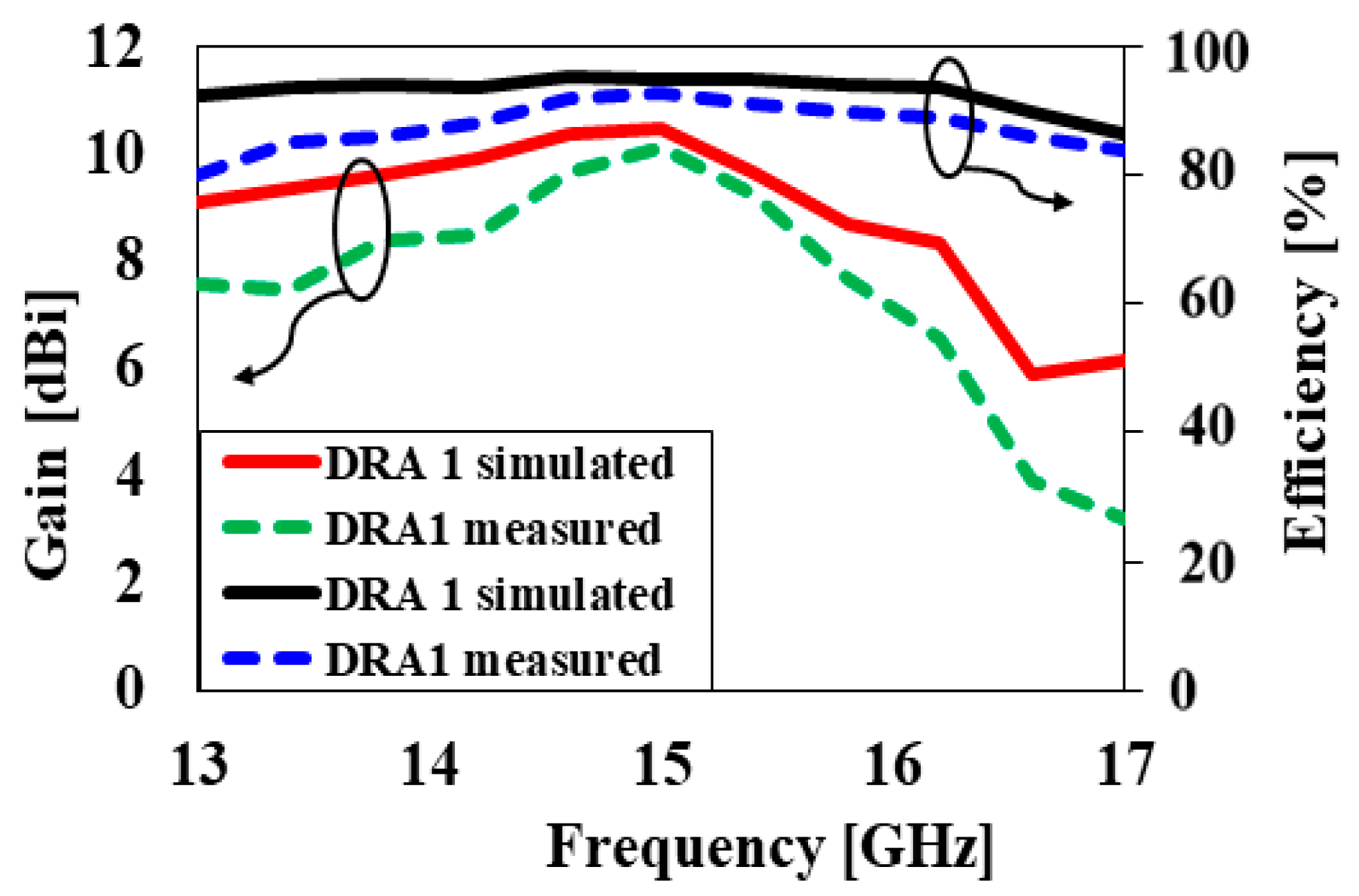
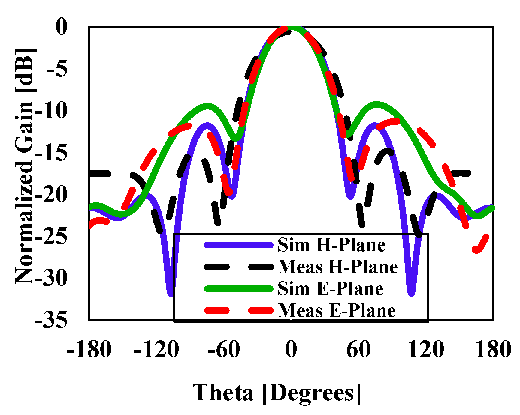
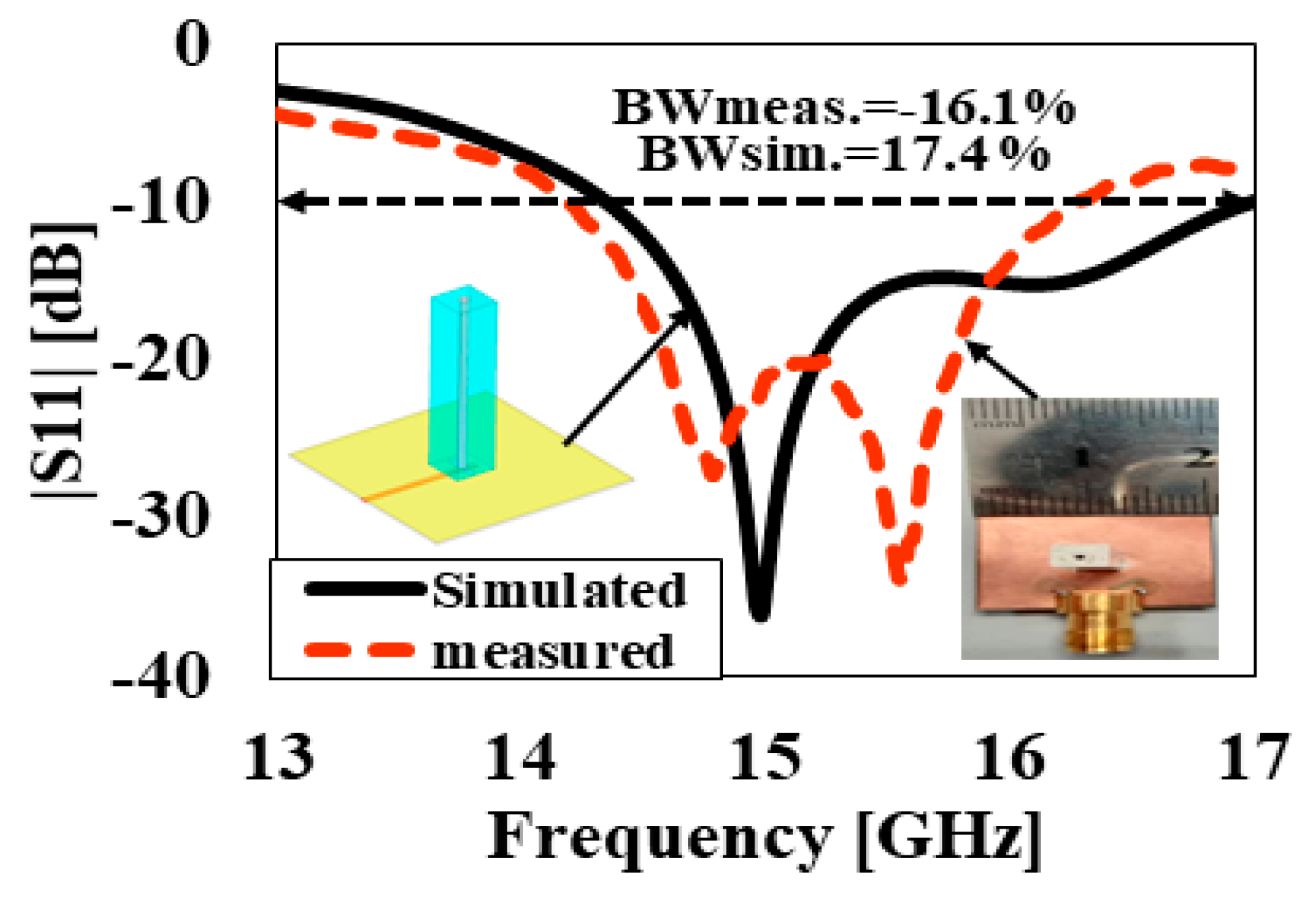
3.1. without Cylindrical Hole (DRA1)
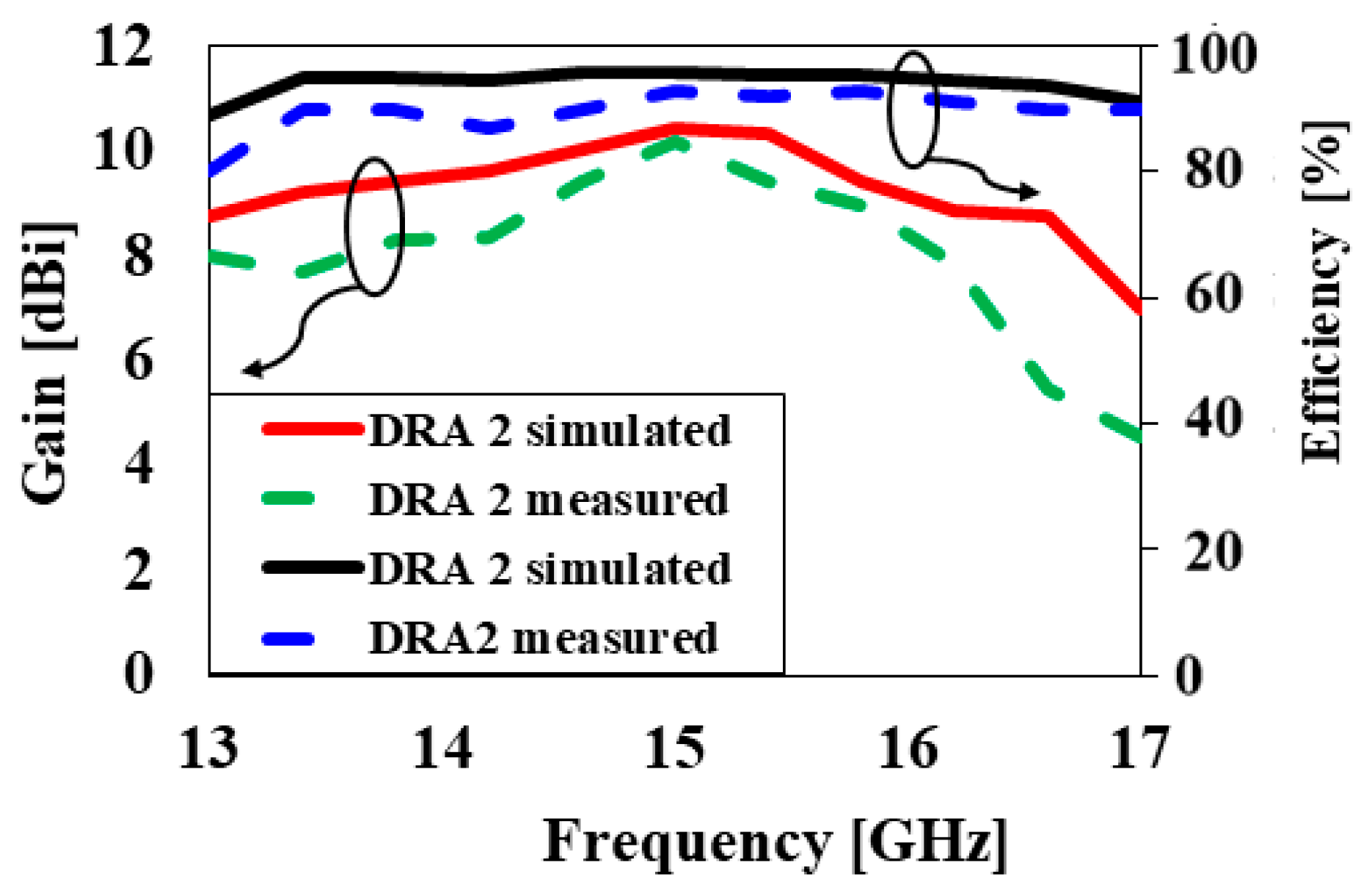
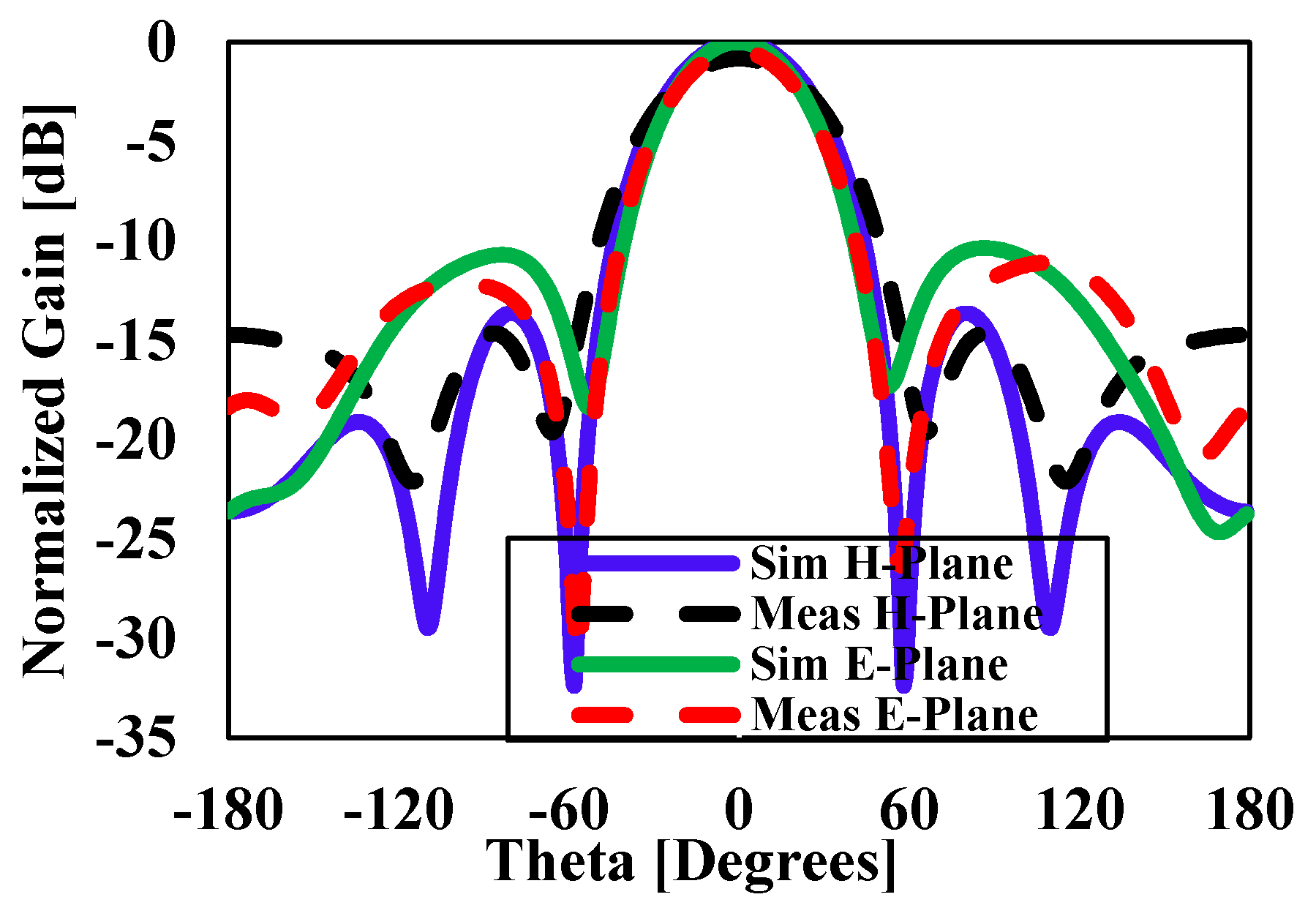
3.2. with Cylindrical Hole (DRA2)
4. Conclusions
Author Contributions
Funding
Acknowledgments
Conflicts of Interest
References
- Ramos, A.; Varum, T.; Matos, J.N. Compact Multilayer Yagi-Uda Based Antenna for IoT/5G Sensors. Sensors 2018, 18, 2914. [Google Scholar] [CrossRef] [PubMed]
- Bengtsson, E.L.; Rusek, F.; Malkowsky, S.; Tufvesson, F.; Karlsson, P.C.; Edfors, O. A Simulation Framework for Multiple-Antenna Terminals in 5G Massive MIMO Systems. IEEE Access 2017, 5, 26819–26831. [Google Scholar] [CrossRef]
- Rahman, M.M.; Islam, M.S.; Wong, H.Y.; Alam, T.; Islam, M.T. Performance Analysis of a Defected Ground-Structured Antenna Loaded with Stub-Slot for 5G Communication. Sensors 2019, 19, 2634. [Google Scholar] [CrossRef] [PubMed]
- Rappaport, T.S.; Xing, Y.; MacCartney, G.R.; Molisch, A.F.; Mellios, E.; Zhang, J. Overview of Millimeter Wave Communications for Fifth-Generation (5G) Wireless Networks-With a Focus on Propagation Models. IEEE Trans. Antennas Propag. 2017, 65, 6213–6230. [Google Scholar] [CrossRef]
- Feng, W.; Li, Y.; Jin, D.; Su, L.; Chen, S. Millimetre-wave backhaul for 5G networks: Challenges and solutions. Sensors 2016, 16, 892. [Google Scholar] [CrossRef]
- Ali, I.; Jamaluddin, M.H.; Kamarudin, M.R.; Gaya, A.; Dahri, M.H. Gain enhancement of dielectric resonator antenna for millimeter wave applications. TELKOMNIKA Telecommun. Comput. Electron. Control 2019, 17, 1670–1673. [Google Scholar] [CrossRef]
- Perron, A.; Denidni, T.A.; Sebak, A.R. High-Gain Hybrid Dielectric Resonator Antenna for Millimeter-Wave Applications: Design and Implementation. IEEE Trans. Antennas Propag. 2009, 57, 2882–2892. [Google Scholar] [CrossRef]
- Garg, R.; Bhartia, P.; Ittipiboon, A. Microstrip Antenna Design Handbook; Arteck House: Boston, MA, USA, 2001. [Google Scholar]
- James, J.R.; Hajj, P.S. Handbook of Microstrip Antennas; peter peregrinus Ltd. London United Kingdom: Oxford, UK, 1989. [Google Scholar]
- Itoh, T. Overview of Quasi-Planar Transmission Lines. IEEE Trans. Microwave Theory Tech. 1989, 37, 275–280. [Google Scholar] [CrossRef]
- Denldni, T.A.; Rao, Q.; Sebak, A.R. Two-ring slot-fed dielectric resonator antenna for dual-frequency operation. Microwave Opt. Technol. Lett. 2005, 44, 448–451. [Google Scholar] [CrossRef]
- Nasir, J.; Jamaluddin, M.H.; Ahmad, K.A.; Kamarudin, M.; Chee, Y.B.; Owais, O. Throughput measurement of a dual-band MIMO rectangular dielectric resonator antenna for LTE applications. Sensors 2017, 17, 148. [Google Scholar] [CrossRef]
- Long, S.A.; McAllister, M.W.; Shen, L.C. The Resonant Cylindrical Dielectric Cavity Antenna. IEEE Trans. Antennas Propag. 1983, 31, 406–412. [Google Scholar] [CrossRef]
- Petosa, A. Dielectric Resonator Antenna Handbook; Artech House Publishers: London, UK, 2007. [Google Scholar]
- Shahadan, N.H.; Jamaluddin, M.H. Steerable Higher Order Mode Dielectric Resonator Antenna With Parasitic Elements for 5G Applications. IEEE Access 2017, 5, 22234–22243. [Google Scholar] [CrossRef]
- Luk, K.M.; Leung, K.W. Dielectric Resonator Antennas; Research Studies Press: Hertfordshire, UK, 2003. [Google Scholar]
- Altaf, A.; Munkyo, S. Triple-Band Dual-Sense Circularly Polarized Hybrid Dielectric Resonator Antenna. Sensors 2018, 18, 3899. [Google Scholar] [CrossRef] [PubMed]
- Denidni, T.A.; Weng, Z. Rectangular dielectric resonator antenna for ultrawideband applications. IEEE Trans. Antennas Propag. 2010, 58, 4059–4062. [Google Scholar] [CrossRef]
- Leung, K.W.; Wong, W.C.; Ng, H.K. Circularly polarized slot-coupled dielectric resonator antenna with a parasitic patch. IEEE Antennas Wirel. Propag. Lett. 2002, 1, 57–59. [Google Scholar] [CrossRef]
- Ryu, K.S.; Kishk, A.A. UWB dielectric resonator antenna having consistent omnidirectional pattern and low cross-polarization characteristics. IEEE Trans. Antennas Propag. 2011, 59, 1403–1408. [Google Scholar] [CrossRef]
- Chair, R.; Kishk, A.A.; Lee, K.F. Wideband stair-shaped dielectric resonator antennas. IET Microwaves Antennas Propag. 2007, 1, 299–305. [Google Scholar] [CrossRef]
- Kishk, A.A. Directive Yagi-Uda dielectric resonator antennas. Microwave Opt. Technol. Lett. 2005, 44, 451–453. [Google Scholar] [CrossRef]
- Hwang, Y.; Zhang, Y.P.; Luk, K.M.; Yung, E.K.N. Gain-enhanced miniaturised rectangular dielectric resonator antenna. Electron. Lett. 1997, 33, 350–352. [Google Scholar] [CrossRef]
- Cicchetti, R.; Faraone, A.; Miozzi, E.; Ravanelli, R.; Testa, O. A High-Gain Mushroom-Shaped Dielectric Resonator Antenna for Wideband Wireless Applications. IEEE Trans. Antennas Propag. 2016, 64, 2848–2861. [Google Scholar] [CrossRef]
- Esselle, N.K.P. Antennas with dielectric resonators and surface mounted short horns for high gain and large bandwidth. IET Microwave Antennas Propag. 2007, 1, 723–728. [Google Scholar]
- Fakhte, S.; Oraizi, H.; Matekovits, L. Gain Improvement of Rectangular Dielectric Resonator Antenna by Engraving Grooves on Its Side Walls. IEEE Antennas Wirel. Propag. Lett. 2017, 16, 2167–2170. [Google Scholar] [CrossRef]
- Guha, D.; Banerjee, A.; Kumar, C.; Antar, Y.M.M. New technique to excite higher-order radiating mode in a cylindrical dielectric resonator antenna. IEEE Antennas Wirel. Propag. Lett. 2014, 13, 15–18. [Google Scholar] [CrossRef]
- Guha, D.; Banerjee, A.; Kumar, C.; Antar, Y.M.M. Higher order mode excitation for high-gain broadside radiation from cylindrical dielectric resonator antennas. IEEE Trans. Antennas Propag. 2012, 60, 71–77. [Google Scholar] [CrossRef]
- Mongia, R.K.; Ittipiboon, A. Theoretical and experimental investigations on rectangular dielectric resonator antennas. IEEE Trans. Antennas Propag. 1997, 45, 1348–1356. [Google Scholar] [CrossRef]
- Mongia, R.K.; Bhartia, P. Dielectric resonator antennas—A Review and General Design Relation for Resonant Frequency and Bandwidth. Int. J. Microwave Millim. Wave Comput. Eng. 1994, 4, 230–247. [Google Scholar] [CrossRef]
- Pan, Y.M.; Leung, K.W.; Luk, K.M. Design of the millimeter-wave rectangular dielectric resonator antenna using a higher-order mode. IEEE Trans. Antennas Propag. 2011, 59, 2780–2788. [Google Scholar] [CrossRef]
- Li, C.H.; Chiu, T.Y. 340-GHz Low-Cost and High-Gain On-Chip Higher Order Mode Dielectric Resonator Antenna for THz Applications. IEEE Trans. Terahertz Sci.Technol. 2017, 7, 284–294. [Google Scholar] [CrossRef]
- Hou, D.; Hong, W.; Goh, W.L.; Chen, J.; Xiong, Y.Z.; Hu, S. D-band on-chip higher-order-mode dielectric-resonator antennas fed by half-mode cavity in CMOS technology. IEEE Antennas Propag. Mag. 2014, 56, 80–89. [Google Scholar] [CrossRef]


| Resonant Modes | a | b | d | Cyl. Hole | |||
|---|---|---|---|---|---|---|---|
| DRA1 without Cyl. hole | 3.84 | 3.84 | 19.22 | 0.34 | 3.2 | 1.65 | |
| DRA2 with Cyl. hole | 3.84 | 3.84 | 19.22 | 0.35 | 3.3 | 1.4 | 0.8 |
| Resonant Modes | BW (Simulated) | BW (Measured) | |
|---|---|---|---|
| DRA1 without hole | 15 | 10.6% (14.3–15.9 GHz) | 10.7% (14.3–15.9 GHz) |
| DRA2 with cyl. hole | 15 | 17.4%(14.3–16.9 GHz) | 16.1%(14.1–16.5 GHz) |
| Parameter | Mode | BW (%) | Gain (dBi) | Efficiency (%) | |
|---|---|---|---|---|---|
| DRA1 () | 10.6% | 10.5 | 97 | ||
| Simulated | 15 | ||||
| DRA2 () with cyl. hole | 17.4% | 10.5 | 98 | ||
| DRA1 () | 10.6% | 10.4 | 95 | ||
| Measured | 15 | ||||
| DRA2 () with cyl. hole | 16.1% | 10.4 | 96 |
| Resonant Mode | |||
|---|---|---|---|
| DRA1 () | ------- | 0.87 | |
| DRA2 () with cyl. hole | 0.8 | 0.67 |
| Ref | Shape | Mode | BW (%) | Gain (dBi) | Eff. (%) | ) | |||
|---|---|---|---|---|---|---|---|---|---|
| [31] | 10 | Rect. | 5.75 | 5.8 | NM | 0.5 | |||
| 24 | 1.6 | ||||||||
| 3.4 | 6.3 | NM | 0.9 | ||||||
| [32] | 11.9 | Rect. | 341 | 7.3 | 7.9 | 74 | 0.5 | ||
| [33] | 10 | Rect. | 7 | 6.2 | 46 | 0.6 | |||
| 135 | |||||||||
| 7 | 7.5 | 42 | |||||||
| PS | 10 | Rect. | 10.7 | 10.4 | 95 | ||||
| 15 | 0.9 | ||||||||
| With cyl. hole | 16.1 | 10.4 | 96 |
© 2020 by the authors. Licensee MDPI, Basel, Switzerland. This article is an open access article distributed under the terms and conditions of the Creative Commons Attribution (CC BY) license (http://creativecommons.org/licenses/by/4.0/).
Share and Cite
Ali, I.; Jamaluddin, M.H.; Gaya, A.; Rahim, H.A. A Dielectric Resonator Antenna with Enhanced Gain and Bandwidth for 5G Applications. Sensors 2020, 20, 675. https://doi.org/10.3390/s20030675
Ali I, Jamaluddin MH, Gaya A, Rahim HA. A Dielectric Resonator Antenna with Enhanced Gain and Bandwidth for 5G Applications. Sensors. 2020; 20(3):675. https://doi.org/10.3390/s20030675
Chicago/Turabian StyleAli, Irfan, Mohd Haizal Jamaluddin, Abinash Gaya, and Hasliza A. Rahim. 2020. "A Dielectric Resonator Antenna with Enhanced Gain and Bandwidth for 5G Applications" Sensors 20, no. 3: 675. https://doi.org/10.3390/s20030675
APA StyleAli, I., Jamaluddin, M. H., Gaya, A., & Rahim, H. A. (2020). A Dielectric Resonator Antenna with Enhanced Gain and Bandwidth for 5G Applications. Sensors, 20(3), 675. https://doi.org/10.3390/s20030675