Article

Design and Analysis of a Novel Piezoceramic Stack-based Smart Aggregate

1
Key Laboratory for Metallurgical Equipment and Control of Ministry of Education, Wuhan University of Science and Technology, Wuhan 430081, China
2
Hubei Key Laboratory of Mechanical Transmission and Manufacturing Engineering, Wuhan University of Science and Technology, Wuhan 430081, China
*
Author to whom correspondence should be addressed.
Sensors 2020, 20(22), 6438; https://doi.org/10.3390/s20226438
Submission received: 12 October 2020 / Revised: 6 November 2020 / Accepted: 9 November 2020 / Published: 11 November 2020
(This article belongs to the Section Electronic Sensors)

Abstract

:
A novel piezoceramic stack-based smart aggregate (PiSSA) with piezoceramic wafers in series or parallel connection is developed to increase the efficiency and output performance over the conventional smart aggregate with only one piezoelectric patch. Due to the improvement, PiSSA is suitable for situations where the stress waves easily attenuate. In PiSSA, the piezoelectric wafers are electrically connected in series or parallel, and three types of piezoelectric wafers with different electrode patterns are designed for easy connection. Based on the theory of piezo-elasticity, a simplified one-dimensional model is derived to study the electromechanical, transmitting and sensing performance of PiSSAs with the wafers in series and parallel connection, and the model was verified by experiments. The theoretical results reveal that the first resonance frequency of PiSSAs in series and parallel decreases as the number or thickness of the PZT wafers increases, and the first electromechanical coupling factor increases firstly and then decrease gradually as the number or thickness increases. The results also show that both the first resonance frequency and the first electromechanical coupling factor of PiSSA in series and parallel change no more than 0.87% as the Young’s modulus of the epoxy increases from 0.5 to 1.5 times 3.2 GPa, which is helpful for the fabrication of PiSSAs. In addition, the displacement output of PiSSAs in parallel is about 2.18–22.49 times that in series at 1–50 kHz, while the voltage output of PiSSAs in parallel is much less than that in parallel, which indicates that PiSSA in parallel is much more suitable for working as an actuator to excite stress waves and PiSSA in series is suitable for working as a sensor to detect the waves. All the results demonstrate that the connecting type, number and thickness of the PZT wafers should be carefully selected to increase the efficiency and output of PiSSA actuators and sensors. This study contributes to providing a method to investigate the characteristics and optimize the structural parameters of the proposed PiSSAs.

1. Introduction

Nowadays, more and more civil infrastructure is undergoing condition deterioration due to age-related degradation [1], fatigue [2,3,4], impact load [5], corrosion [6,7], environmental conditions, etc. The challenges of deteriorating civil infrastructure call for developing reliable and cost-effective solutions to structural health monitoring (SHM) of civil infrastructure. In SHM of civil infrastructure, notable research based on advanced algorithms, such as damage index-based damage assessment [8,9], image-based damage locating [10] and artificial intelligence algorithms [11], have been reported to provide solutions to real-time monitoring and early warning of civil infrastructure [12,13] by using various sensors, such as strain gauges [14,15], piezoelectric transduces [16,17], optical fiber sensors [18,19], etc. With advantages of low cost, wide bandwidth [20] and quick time response [21,22], apart from in SHM of civil infrastructure, piezoelectric transducers have also been widely used in other fields, including aerospace [23,24,25,26], transportation [27,28] and energy [29,30], and they have displayed good applicability in both passive and active situations [31,32], such as vibration sensing [33], acoustic emission [34], active sensing and electromechanical impedance-based damage detection [35,36,37].
With a tailored protective shell [38], the piezoceramic-based smart aggregate (SA) extends its survival life and it has been widely used in SHM of concrete structures. SAs are usually embedded in concrete structures during the casting process and usually serve as either a transmitter or a sensor to actively transmit stress wave or detect the wave [39,40,41,42]. After the detected signal is processed, the health state of the structure is evaluated, and early warnings are alerted if the structure is in danger. Recently, cracks under seismic and quasi-static load [43,44,45], concrete strength and water percentage in early age [46,47,48], impact and blast load [49,50], debonding or bond slip [51,52], leakage [53] and corrosion of the reinforced bar [54] in various types of concrete structures, including pipes [55], columns [56,57], beams [58,59] and piles [60] of concrete or reinforced concrete (RC), are detected or monitored with the help of SAs.
A typical SA consists of a single piezoelectric wafer, a waterproof and insulated coating, a protective shell and connecting wires. Since SA was first introduced [61,62], the structure of SA is being continuously improved to satisfy the concerns of SHM in concrete structures. In the first generation of SAs, the piezoelectric wafer was protected by a concrete casted block, and this SA only generated a stress wave in a certain direction [63,64]. In the second generation of SA, the concrete protective shell was replaced by two marble pieces to avoid structural destruction and extend the survival time [65,66]. Moreover, to increase the signal to noise ratio of the detected signal, the piezoelectric wafer was surrounded by a copper shield before it was assembled in the marble shell. To excite stress wave in a two-dimensional space omni-directionally, the piezoelectric wafer in the first and second generation SAs was replaced with a piezoelectric tubular cylinder, and this tubular SA has been used to successfully locate damage in two-dimensional concrete slabs [67,68,69]. A spherical SA is developed by Kong et al. [70,71] to generate or receive stress wave omni-directionally in a three-dimensional space. In this spherical SA, the traditional single piezoelectric wafer is substituted by a piezoelectric spherical shell, and both the simulation and experimental results verify that the spherical SA has an excellent actuating and sensing performance. Unlike these aforementioned SAs, a special SA with piezoelectric wafers working in d15 mode is designed to detect shear stress in concrete structures [72]. Moreover, to reduce costs of the traditional SAs due to cable laying, a Zigbee-based wireless SA sensor is designed for SHM in concrete structures; however, the stress wave is still excited by a traditional wired SA transmitter [73]. Moreover, to better understand the electro-mechanical characteristics of SAs, Wang et al. [65] developed a theoretical model to study the performance of the SA with marble protection based on the piezo-elasticity theory [74,75,76,77].
The development of SAs mainly focuses on how to transmit or sense stress waves uniformly in omni-directions or how to avoid functional destruction and prolong the lifetime of SAs. However, how to increase the efficiency and output of SAs is seldom investigated. Recently, the piezoelectric stack is widely used as actuators to generate force or displacement for precision control of, e.g., MEMS, robots [78] and optical instruments [79]. In the stack actuator, many individual piezoelectric wafers are connected mechanically and electrically to increase the displacement or force output. However, the stack is seldom used as sensors to detect signals, and especially the piezoelectric stack has never been previously employed for SA actuators and sensors. Moreover, due to the strong scattering characteristics of concrete structures [80], elastic stress waves are easily attenuated during propagation. Therefore, SAs with large output are helpful for SHM of large concrete structures. In this paper, a novel piezoceramic stack-based smart aggregate (PiSSA) is developed to increase the output of SA actuators and sensors. In the proposed PiSSA, the single piezoelectric wafer in the traditional SA is replaced by a piezoelectric stack, where the piezoelectric wafers are electrically connected in series or parallel connections. For easy connection, three types of piezoelectric wafers with different electrode patterns are designed and fabricated. Moreover, based on the theory of piezo-elasticity, a simplified one-dimensional model is established to compare the electromechanical, transmitting and sensing performances of PiSSA actuators or sensors with series and parallel PZT wafers, and the model was validated by experiments.
The rest of the paper is organized as follows. Section 2 introduces the structure and fabrication procedure of PiSSAs with series and parallel wafers. Section 3 derives a simplified one-dimensional model for PiSSA actuators and sensors with series or parallel PZT wafers based on the piezo-elastic theory. Section 4 presents a comparative study of the electromechanical, transmitting and sensing performances of PiSSAs as well as the experimental validation. Section 5 concludes the paper.

2. Structure and Fabrication Procedure of PiSSAs

2.1. Structure of PiSSAs

As shown in Figure 1, to be electrically connected easily, three types of PZT wafers (PZT-0, PZT-1 and PZT-2) with different electrode patterns are designed. As shown in Figure 1a, PZT-0 is the standard electrode pattern, and the positive and negative electrodes are placed on two surfaces individually. PZT-1, as shown in Figure 1b, is the wrap around electrode pattern, and the negative electrode is connected to the surface of the positive electrode. PZT-2, as shown in Figure 1c, is the double-side wrap around electrode pattern, and both the positive and negative electrodes are connected to the other side.
To protect PiSSAs and reduce the electromagnetic interference, a copper cylinder and cover are also designed.

2.2. Fabrication Procedure of PiSSAs

Firstly, the individual PZT wafers are stacked together by conductive adhesive. As shown in Figure 2, the stack in series is connected by a number of PZT-0s, and the PZT wafers are directly electrically connected in series. Unlike the stack in series, the stack in parallel is comprised of PZT-1 and PZT-2, and the PZTs are electrically connected in parallel with the help of the designed electrode pattern. When the PZT wafers are stacked, the two adjacent PZT wafers are bonded by conductive adhesive and kept under a constant compression load of 150 N for 24 h.
Secondly, the wire is soldered to the cylindrical surface of the stack. Thirdly, as shown in Figure 3, the lower cover and the cylinder are firstly assembled using epoxy resin, and they are kept under the same compression load for another 24 h. In this step, the gap between the cylinder and the stack is filled with epoxy. At last, the upper cover is assembled and kept under the same load for 24 h.

3. Fundamentals of PiSSAs

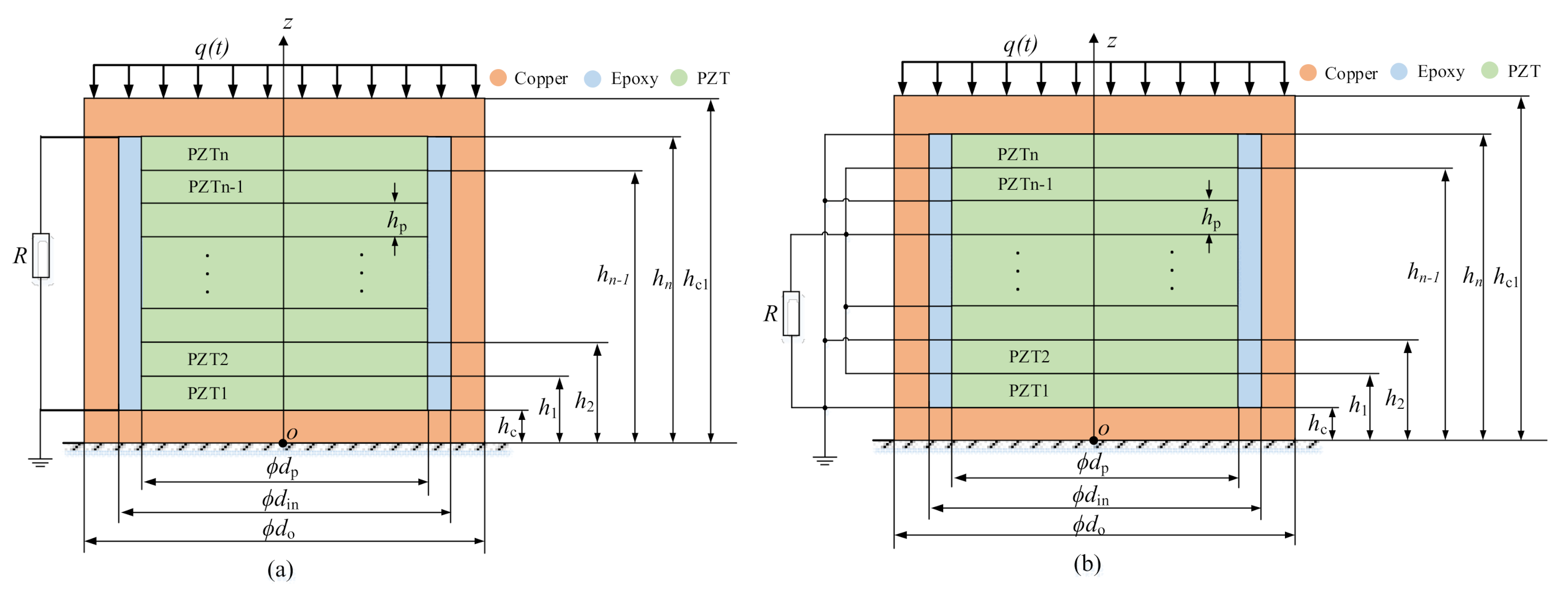
3.1. Simplified Model of PiSSAs

Since PiSSAs are employed to transmit elastic stress waves in the axial direction, PiSSA actuators and sensors with series or parallel wafers are simplified to a one-dimensional axial model, as shown in Figure 4 and Figure 5, respectively. As shown in Figure 4, when an alternating voltage is inputted to PiSSA actuator, it excites an alternating strain on two surfaces of PiSSA, and PiSSA eventually excites ultrasounds in the concrete structures. As shown in Figure 5, when an alternating strain or stress is applied on the surface of PiSSA sensor, an alternating voltage is generated on the piezoelectric wafers.
In this model, n PZT wafers are connected in series or parallel. The thickness of the copper covers and PZTs are hc and hp, respectively. The polarization direction of PZTs is along the z-axis, and the piezoelectric coefficient is positive if the polarization direction is along the positive z-axis; otherwise, it is negative. Note that the thickness and properties of the PZTs in PiSSAs are the same.
The fundamental equations for the ith composite layer of the PZT wafer, copper cylinder and epoxy are expressed as [65]
σ p i = C 33 p ε p i e 33 E i D i = e 33 ε p i + κ 33 ε E i E i = ϕ i z D i z = 0     i = 1 ,   2 , ,   n   ( PZT   wafer )
σ c i = C 33 c ε c i σ e i = C 33 e ε e i       i = 1 ,   2 , ,   n   ( copper   cylinder   and   epoxy )
where σci, σei and σpi, are the stresses of the copper, epoxy and the ith PZT wafer in the z-axis direction, respectively; εei, εci and εpi are the strains of the copper, epoxy and the ith PZT wafer in the z-axis direction, respectively; Di, ϕ i and Ei are the electric displacement, electric potential and electric field of the ith PZT wafer, respectively; C33c, C33p and C33e are the Young’s moduli of the copper, the PZT wafer and the epoxy, respectively; and [65]
e 33 = C 33 p d 33 κ 33 ε = κ 33 σ C 33 p d 33 2
with κ 33 σ and d33 the permittivity coefficient and piezoelectric coefficient, respectively.
In addition, the kinematic equation of the ith layer is expressed by
F p i z = ρ p S p + ρ e S e + ρ c S c 2 u p i t 2     i = 1 ,   2 , ,   n
where t is the time; upi is the displacement in the z-axis direction of the ith layer; Fpi is the force applied on the ith layer in the z-axis direction; ρc, ρe and ρp are the densities of the copper, the epoxy and the PZT materials, respectively; and S p = π d p 2 / 4 , S c = π d o 2 d in 2 / 4 and S e = π d p 2 d in 2 / 4 are the cross-sectional area of the PZT wafer, the copper cylinder and the epoxy where din and do and are the inner and outer diameters of the copper cylinder respectively. dp is the diameter of the PZT wafer.
Moreover, there are
F p i = σ p i S p + σ e i S e + σ c i S c ε p i = ε c i = ε e i = u p i z     i = 1 ,   2 , ,   n
Hence, combining Equations (1)–(5) yields
χ 0 2 u p i z 2 = χ 1 2 u p i t 2 E i z = χ 2 2 u p i z 2       i = 1 ,   2 , ,   n
where the constants are defined by χ 0 = S p C 33 p + χ 3 + S c C 33 c + S e C 33 e , χ 1 = S p ρ p + S c ρ c + S e ρ e , χ 2 = e 33 / κ 33 ε and χ 3 = e 33 2 / κ 33 ε .
Suppose that a harmonic voltage U(t) or a harmonic force q(t) is applied to PiSSAs and the harmonic load is given by
U ( t ) = U 0 e j ω t         ( for   PiSSA   actutors ) q ( t ) = q 0 e j ω t             ( for   PiSSA   sensors )
where U0 and q0 are the amplitude of the voltage and force, respectively; j is the unit imaginary number; and ω is the angular frequency.
For the harmonic and steady vibration, the displacement upi and electric potential ϕ i at the ith layer are expressed by
u p i = u p i ( z ) e j ω t ϕ i = ϕ i ( z ) e j ω t F p i = F p i ( z ) e j ω t     i = 1 ,   2 , ,   n
Hence, combining Equation (1) and Equations (6)–(8) gives the expression
u p i ( z ) = A p i sin ( k p z ) + B p i cos ( k p z ) ϕ p i ( z ) = χ 2 A p i sin ( k p z ) + B p i cos ( k p z ) + C p i z + D p i F p i ( z ) = χ 0 k p A p i cos ( k p z ) B p i sin ( k p z ) + χ 3 S p C p i           i = 1 ,   2 , ,   n
where k p 2 = χ 1 ω 2 / χ 0 , Api, Bpi, Cpi and Dpi, are constants which are determined by the mechanical and electric boundary conditions.
Similarly, the corresponding equations for the upper and lower copper covers are obtained
u c i ( z ) = A c i sin ( k c z ) + B c i cos ( k c z ) F c i ( z ) = S C 33 c k c A c i cos ( k c z ) B c i sin ( k c z )               i = 1 , 2
where χ 4 = ρ c / c 33 c and k p 2 = χ 4 ω 2 are constants; S = π d o 2 / 4 is the cross-sectional area of the copper cover; and Aci and Bci are the constants which are determined by the mechanical and electric boundary conditions of PiSSAs.
Therefore, there are totally 4 + 4 n variables in Equations (9) and (10), and the variables can be obtained by the mechanical and electric boundary conditions of PiSSAs.

3.2. Boundary Conditions of PiSSA Actuators

As shown in Figure 4, when a harmonic external voltage U(t) is input to PiSSA, it works as an actuator to transmit stress waves. Therefore, the mechanical boundary conditions of PiSSA actuators are given as
{ F c 1 ( z ) | z = 0 = 0 , F c 2 ( z ) | z = h c 1 = 0 F p 1 ( z ) | z = h c = F c 1 ( z ) | z = h c F p n ( z ) | z = h n = F c 2 ( z ) | z = h n F p i 1 ( z ) | z = h i 1 = F p i ( z ) | z = h i 1 u p 1 ( z ) | z = h c = u c 1 ( z ) | z = h c u p n ( z ) | z = h n = u c 2 ( z ) | z = h n u p i 1 ( z ) | z = h i 1 = u p i ( z ) | z = h i 1 i = 2 , 3 , , n   ( for   PiSSA   actuators )
The electric current of the ith PZT in PiSSA actuators is given by
I p i ( t ) = d Q i ( t ) d t = d S p D i ( t ) d s d t = j ω S p e 33 C p i U 0 e j ω t = I p i ( ω ) e j ω t
where I p i ( ω ) = j ω S p e 33 C p i U 0 .
In addition, the electric boundary conditions for PiSSA actuators are expressed as
ϕ p 1 ( z ) z = h c 1 = 0 ϕ p n ( z ) z = h n = U 0 ϕ p i 1 ( z ) z = h i 1 = ϕ p i ( z ) z = h i 1 I p 1 ( ω ) = I p 2 ( ω ) = = I p n ( ω ) i = 2 ,   3 ,   ,   n 1 ( for   PiSSAs   in   series )  
or
ϕ p 1 ( z ) z = h c 1 = 0 ϕ p n ( z ) z = h n = U 0 ϕ p i 1 ( z ) z = h i 1 = ϕ p i ( z ) z = h i 1 I p 1 ( ω ) = I p 2 ( ω ) = = I p n ( ω ) i = 2 ,   3 ,   ,   n 1 ( for   PiSSAs   in   parallel )  

3.3. Boundary Conditions for PiSSA Sensors

As shown in Figure 5, when PiSSA works as sensors, an external uniform distributed force q(t) is applied on one side of PiSSA and the other side is fixed. Therefore, the mechanical boundary conditions are given as
{ u c 1 ( z ) z = 0 = 0 ,   F c 2 ( z ) z = h c 1 = q 0 S F p 1 ( z ) z = h c = F c 1 ( z ) z = h c F p n ( z ) z = h n = F c 2 ( z ) z = h n F p i 1 ( z ) z = h i 1 = F p i ( z ) z = h i 1 u p 1 ( z ) z = h c = u c 1 ( z ) z = h c u p n ( z ) z = h n = u c 2 ( z ) z = h n u p i 1 ( z ) z = h i 1 = u p i ( z ) z = h i 1 i = 2 ,   3 , ,   n   ( mechanical   boundary   conditions )
Similarly, the electric boundary conditions for PiSSA sensors are expressed as
ϕ p 1 ( z ) z = h c 1 = 0 ϕ p n ( z ) z = h n = I p i ( ω ) R ϕ p i 1 ( z ) z = h i 1 = ϕ p i ( z ) z = h i 1 I p 1 ( t ) = I p 2 ( t ) = = I p n ( t ) i = 2 ,   3 ,   ,   n 1   ( for   PiSSAs   in   series )  
or
ϕ p 1 ( z ) z = h c = ϕ p i ( z ) z = h p i = ϕ p i + 1 ( z ) z = h p i = 0           i = 2 ,   4 ,   6 ϕ p n ( z ) z = h n = ϕ p i ( z ) z = h i = ϕ p i + 1 ( z ) z = h i = R i n I p i ( ω )       i = 3 ,   5 ,   7 ( for   PiSSAs   in   parallel )  
where R is the resistor of the closed electric circuit.

3.4. Analytical Solutions to PiSSAs

Combining Equations (9)–(15), 4 + 4 n equations are totally obtained for a given frequency ω, and the 4 + 4 n variables in Equations (9) and (10) can be solved by these 4 + 4 n equations by numerical computation with the help of a computer.
As a result, the impedance of PiSSA actuators for a given angular frequency ω is given by
Z ( ω ) = U ( t ) I p i ( t ) = U 0 I p i ( ω )                     ( for   PiSSAs   in   series ) U ( t ) i n I p i ( t ) = U 0 i n I p i ( ω )       ( for   PiSSAs   in   parallel )
Hence, the electromechanical coupling factor of PiSSAs can be obtained by [81]
k 2 = f a 2 f r 2 f a 2
where fr and fa are the resonance and anti-resonance frequencies which can be obtained by Equation (16).
The voltage output of PiSSA sensors is given by
U ( ω ) = I p i ( ω ) R                     ( for   PiSSAs   in   series ) R i n I p i ( ω )             ( for   PiSSAs   in   parallel )
In addition, the average power of PiSSAs is expressed as
P ( ω ) = U ( ω ) I p i ( ω )                     ( for   PiSSAs   in   series ) U ( ω ) i n I p i ( ω )             ( for   PiSSAs   in   parallel )

4. Performance Comparison of PiSSAs

4.1. Parameters of PiSSAs

After the simplified model is established, the electromechanical, transmitting and sensing performance of PiSSAs whose wafers are electrically connected in series and parallel are compared in this section. The structural dimensions and material parameters are listed in Table 1 and Table 2, respectively.

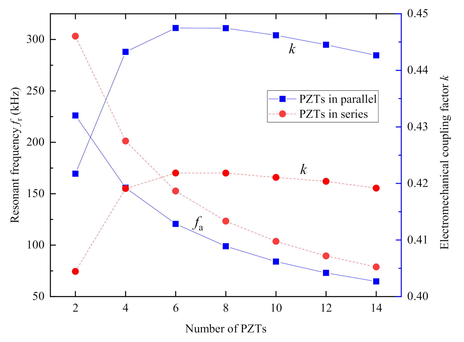
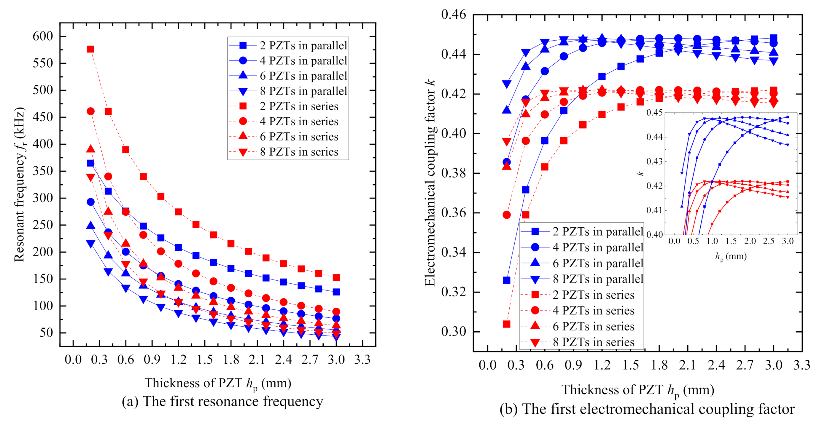
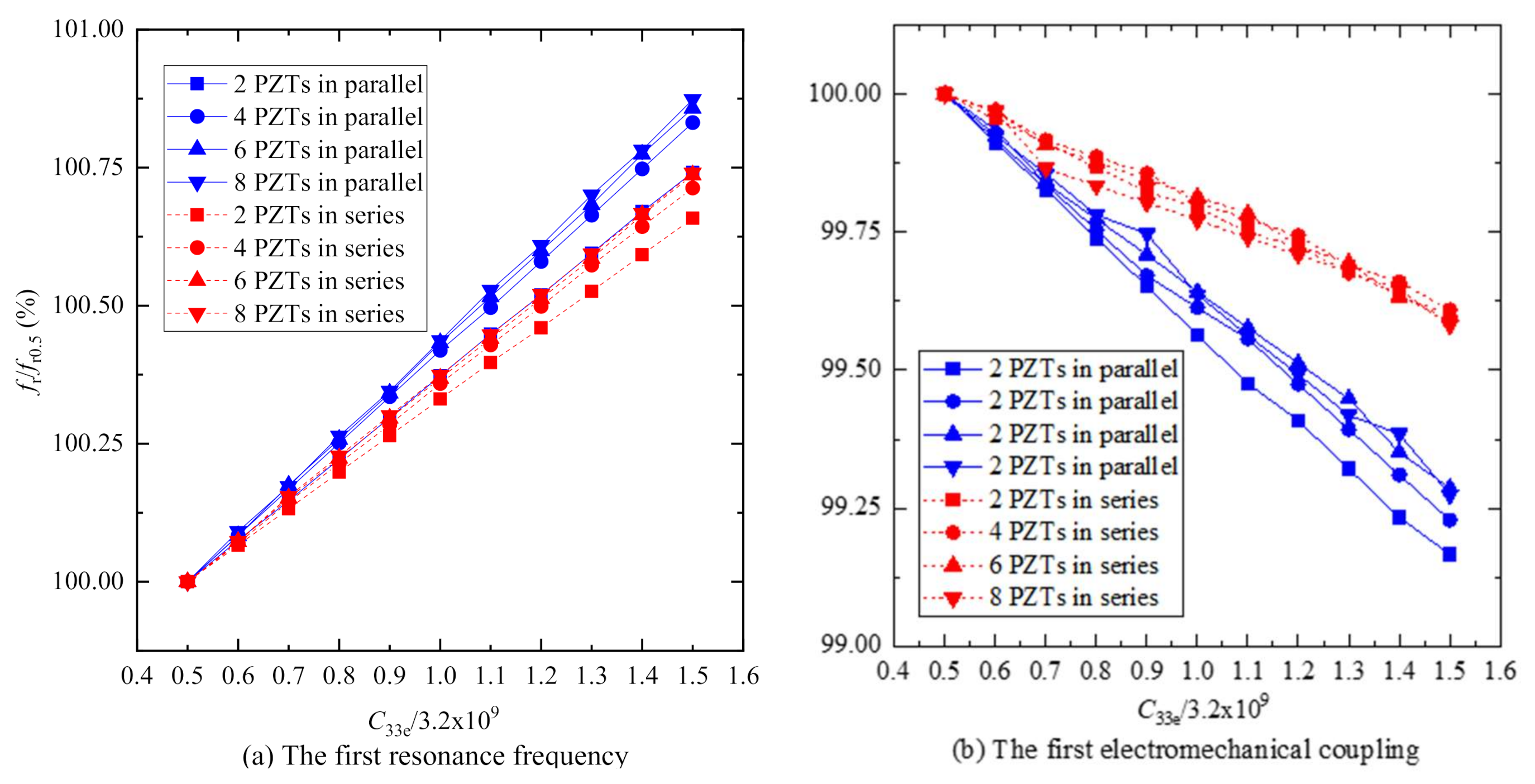
4.2. Electromechanical Performance

Figure 6 plots the curves of the first resonance frequency fr and the electromechanical coupling factor k versus the number of the PZT wafers n. Figure 6 indicates that the first resonance frequency fr of both PiSSAs with series and parallel connected wafers decreases as the number of the PZT wafers n increases while the first electromechanical coupling factor increases firstly and then decreases gradually as the number increases. Figure 6 also shows that the first resonance frequency fr of PiSSAs with series wafers is about 1.21–1.34 times that in the case of parallel wafers, and the electromechanical coupling factor k of PiSSAs with series wafer is about 0.94–0.96 times that in parallel. Moreover, the first electromechanical coupling factor reaches the peak when the number of the PZT wafers is 6 for the given structural parameters, which indicates that there is an optimal value for the number of the PZT wafers for a given structure. Since PiSSA, as shown in Figure 3a, mainly consists of a copper cylinder, an upper cover, a lower cover, a piezoelectric stack and epoxy, the height of the copper cylinder and epoxy increases as the number of piezoelectric wafers increases, and they dissipate more energy. Moreover, the piezoelectric wafers transfer more mechanical energy from electrical energy as the number increases. When the change of the energy dissipated by the structure is less than the change of the energy transferred by the stack, the electromechanical coupling factor increases, and, on the other side, the factor decreases. As a result, the first electromechanical coupling factor increases firstly and then decreases gradually as the number increases, and there is an optimal number where the first electromechanical coupling factor reaches the maximum value.
Figure 7 shows the curves of the first resonance frequency fr and electromechanical coupling factor of PiSSAs versus the thickness of the PZT wafer hp, respectively. Figure 7a reveals that the first resonance frequencies of PiSSAs with series or parallel wafers decrease as the thickness of the PZT wafer hp increases. Figure 7b illustrates that the first electromechanical coupling factor firstly increases and then decreases as the thickness hp increases, and the first electromechanical coupling factor in parallel is slightly larger than that with series wafers, which indicates that there is an optimal value for the thickness hp of the PZT wafers for a given structure.
Figure 8 plots the curves of the first resonance frequency fr and electromechanical coupling factor k versus the Young’s modulus of the epoxy C33e. Figure 8a reveals that the first resonance frequency fr of PiSSA with series wafers just increases 0.74% as the Young’s modulus C33e increases from 0.5 to 1.5 times 3.2 GPa while the frequency of PiSSA with parallel wafer increases 0.87%. Similarly, Figure 8b illustrates that the first electromechanical coupling factor k of PiSSA with series wafers decreases 0.42% as the Young’s modulus C33e increases from 0.5 to 1.5 times 3.2 GPa while the factor of PiSSA with parallel wafers decreases 0.83%. Therefore, the curves in Figure 8 indicates that the Young’s modulus of the epoxy C33e has little effect on the first resonance frequency fr and electromechanical coupling factor k, which can be helpful for the design of PiSSAs.

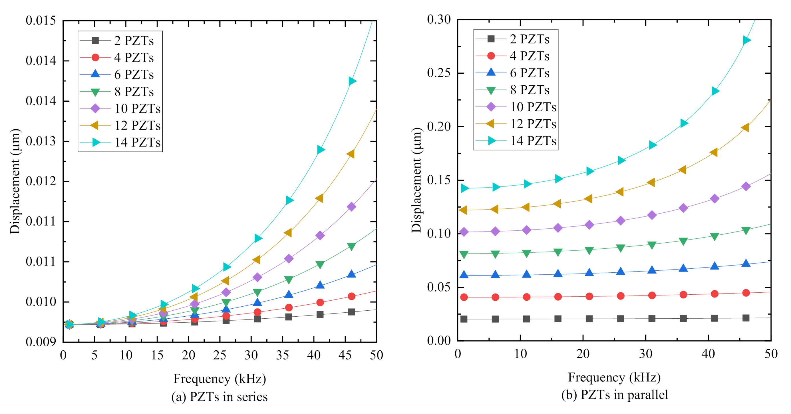
4.3. Transmitting Performance

Figure 9 plots the curves of the displacement of PiSSAs with series or parallel wafers under an excitation voltage with an amplitude of 100 V versus the frequency of the excitation voltage. Figure 9 illustrates that the displacement of PiSSAs with series or parallel wafers increases as the number of the connected PZTs increases, and the displacement also increases as the frequency increases. Compared with Figure 9b, Figure 9a shows that the displacement of PiSSAs with parallel wafer is about 2.18–22.49 times that with series wafers, which indicates that PiSSAs in parallel are much more suitable for the use as actuators to excite stress waves. Moreover, there are only one or two wafers in the conventional SA, and, therefore, PiSSA actuators with more piezoelectric wafers generate a larger output and display a better transmitting performance than the conventional one.

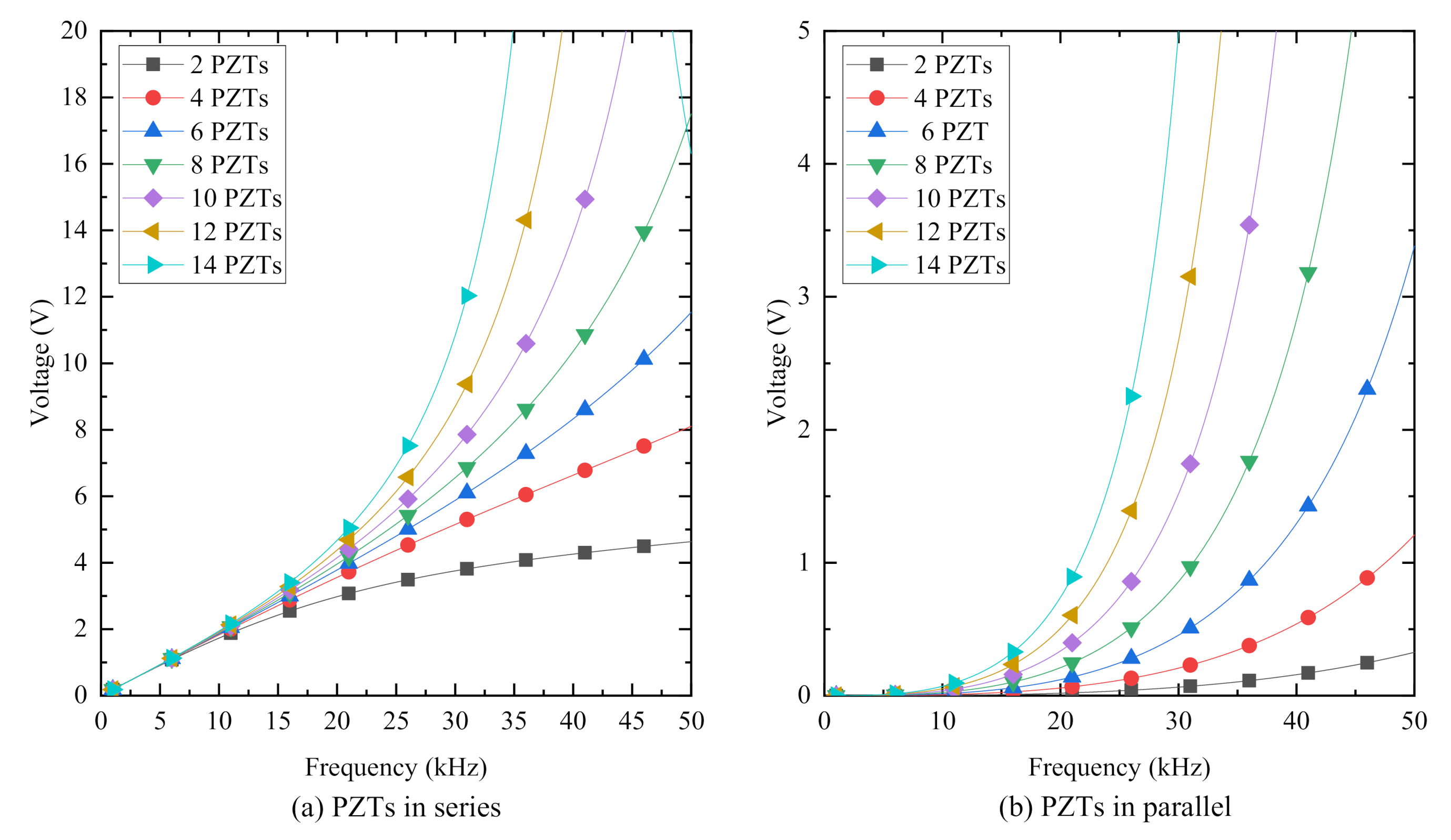
4.4. Sensing Performance

Since the output voltage is the most important property of PiSSA sensors, the voltage is compared in this section and the voltage is obtained by Equation (18).
Figure 10 plots the curves of the output voltage of PiSSAs in series and parallel connection with an external resistor 10 kΩ under a uniform distributed load with an amplitude of 0.1 MPa versus the frequency of the excitation load. Figure 10 reveals that the voltage of PiSSAs with wafers in series or parallel connection increases as the number of the connected PZTs increases, and the voltage also increases as the frequency increases. Compared with Figure 10b, Figure 10a shows that the output voltage of PiSSAs with series wafers is much larger than that of PiSSAs with parallel wafers, which indicates that PiSSAs with series wafer are much more suitable for the use as sensors to detect stress waves. Moreover, there are only one or two wafers in the conventional SA, and the two wafers are usually connected in parallel. Therefore, PiSSA sensors with more piezoelectric wafers output a larger voltage and show a better sensing performance than the conventional one.
It should be noted that the output voltage of PiSSAs may vary as the external matching resistor changes, and the external matching resistor should be chosen carefully [82].

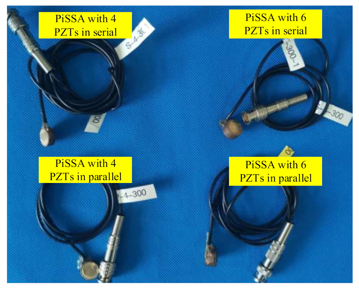
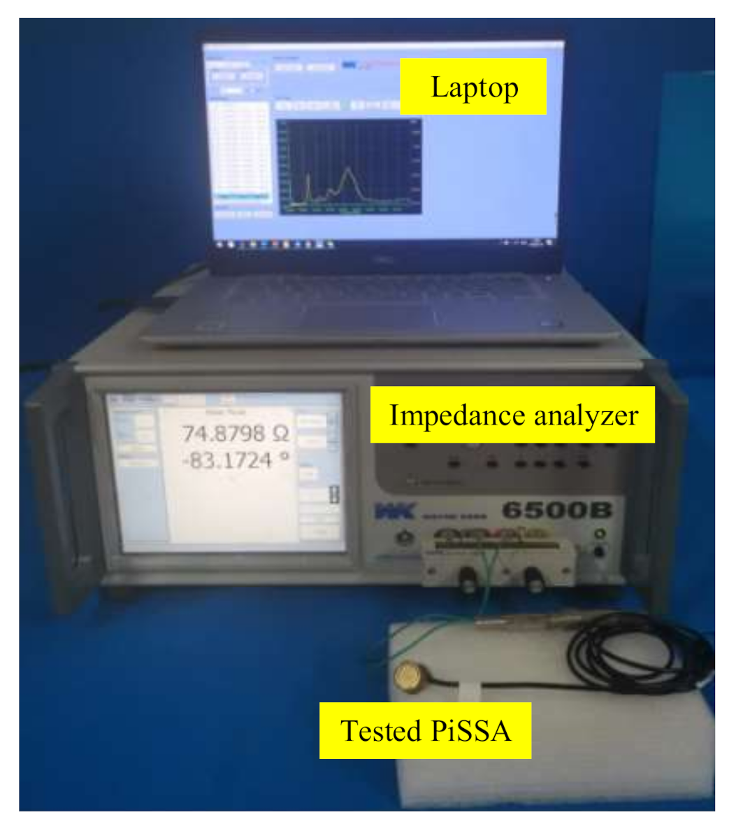
4.5. Experimental Validation

To validate the simplified model of PiSSAs, four PiSSAs including two PiSSAs with series wafers and two PiSSAs with parallel wafers (Figure 11) were fabricated and their impedance signatures were measured by an impedance analyzer. To decrease the adverse effect of the fabrication process of PiSSAs with too many piezoelectric wafers, the number of the PZT wafers were 4 and 6, respectively. As shown in Figure 12, the measured experimental setup included an impedance analyzer (Wayne Kerr 6500B), PiSSAs and a laptop.
Figure 13 plots the measured impedance signatures of PiSSAs, and, due to the effect of the conductive adhesive and soldering, some noises are observed in the figures, especially in Figure 13d. Table 3 compares the measured and the theoretical first resonance and anti-resonance frequencies of the four fabricated PiSSAs. Table 3 reveals that the theoretical values of the first resonance and anti-frequencies are in good agreement with the experimental ones, and the relative error is about 0.40–10.57%. Therefore, the experimental results validate that the simplified model for PiSSAs can be used to study the performance of PiSSAs.
It should be noted that the conductive adhesive between the adjacent two piezoelectric wafers is not considered in the simplified model, which may bring about additional noise and error between the experimental and theoretical data as the number of the piezoelectric wafers increases. Moreover, the features of PiSSA sensors, such as the repeatability, noise/signal ration, hysteresis behavior, etc., are also important and should be tested.

4.6. Discussion

Based on the simplified model of PiSSAs, the electromechanical, transmitting and sensing performance of PiSSAs with series and parallel wafers are compared. The theoretical results indicate that the first resonance frequency and the first electromechanical coupling factor are influenced by the number, electrical connecting type and thickness of the PZT wafers. The displacement and voltage output of PiSSAs are influenced greatly by the connecting type and number of the PZT wafers. Therefore, the connecting type, number and thickness of the PZT wafers should be carefully selected to increase the efficiency and output of PiSSA actuators or sensors when PiSSAs are designed. This study also contributes to provide a method to optimize the structural parameters of PiSSA sensors and actuators in our future work.
Moreover, four PiSSAs including two PiSSAs with series wafers and two PiSSAs with parallel wafers were fabricated, and the measured electromechanical data of the four PiSSAs are in good consistency with the theoretical one.

5. Conclusions

A novel piezoceramic stack-based smart aggregate (PiSSA) is proposed to improve the efficiency and output performance over the traditional SAs with only one piezoceramic patch. PiSSA is especially applicable to the situations where the signal easily attenuates. In PiSSA, the piezoelectric wafers are electrically connected in series or parallel. For easy series or parallel connection, three types of PZT wafers with different electrode patterns are designed. Based on the theory of piezo-elasticity, a simplified one-dimensional model is established to investigate the characteristics of the proposed PiSSAs. By using this simplified model, the electromechanical, transmitting and sensing characteristics of PiSSAs with series and parallel wafers are theoretically investigated, and the simplified model was also validated by experiments. The following conclusions are drawn:
(1) The first resonance frequency of PiSSAs where the wafers are in series or parallel connection decreases as the number and thickness of the PZT wafers increases, and the first electromechanical coupling factor increases firstly and then decreases gradually as the number and thickness increases, which reveals that there is an optimal number and thickness for the electromechanical coupling factor.
(2) The first resonance frequency and the first electromechanical coupling factor of PiSSA where the wafers are in series or parallel connection changes no more than 0.87%, as the Young’s modulus of the epoxy increases from 0.5 to 1.5 times 3.2 GPa, which can be helpful for the fabrication of PiSSAs.
(3) The displacement output of PiSSAs with parallel wafers is about 2.18–22.49 times that of the case of series wafers within 1–50 kHz, while the voltage output of PiSSAs with parallel wafers is much less than that of PiSSAs with series wafers, which indicates that PiSSAs with parallel wafers are much more suitable for working as actuators to excite stress waves and PiSSAs in series are suitable for working as a sensor to detect the waves.
This study contributes to providing a method to investigate the performance of PiSSAs. The future work will involve the structural parameters and external matching resistor optimization, and the transmitting and sensing performance test of PiSSAs. The future work will also involve the theoretical and experimental study of PiSSA sensor features, such as repeatability, hysteresis behavior, etc.

Author Contributions

Conceptualization and formal analysis, G.L.; investigation, X.Z.; methodology, T.W.; validation, B.T. and Z.H.; writing—original draft preparation, X.Z. and B.T.; and writing—review and editing, G.L. and T.W. All authors have read and agreed to the published version of the manuscript.

Funding

This research was funded by National Natural Science Foundation of China (Grant Nos. 51808417 and 51475339) and Hubei Key Laboratory of Mechanical Transmission and Manufacturing Engineering of China (Grant No. 2018A09).

Conflicts of Interest

The authors declare no conflict of interest. The funders had no role in the design of the study, the interpretation of data and the decision to publish the results.

References

  1. Kim, I.-H.; Jeon, H.; Baek, S.-C.; Hong, W.H.; Jung, H.-J. Application of crack identification techniques for an aging concrete bridge inspection using an unmanned aerial vehicle. Sensors 2018, 18, 1881. [Google Scholar] [CrossRef] [PubMed] [Green Version]
  2. Peng, J.; Xiao, L.; Zhang, J.; Cai, C.S.; Wang, L. Flexural behavior of corroded hps beams. Eng. Struct. 2019, 195, 274–287. [Google Scholar] [CrossRef]
  3. Huo, L.; Li, C.; Jiang, T.; Li, H.-N. Feasibility study of steel bar corrosion monitoring using a piezoceramic transducer enabled time reversal method. Appl. Sci. 2018, 8, 2304. [Google Scholar] [CrossRef] [Green Version]
  4. Peng, J.; Hu, S.; Zhang, J.; Cai, C.S.; Li, L.-y. Influence of cracks on chloride diffusivity in concrete: A five-phase mesoscale model approach. Constr. Build. Mater. 2019, 197, 587–596. [Google Scholar] [CrossRef]
  5. Xu, K.; Deng, Q.; Cai, L.; Ho, S.; Song, G. Damage detection of a concrete column subject to blast loads using embedded piezoceramic transducers. Sensors 2018, 18, 1377. [Google Scholar] [CrossRef] [PubMed] [Green Version]
  6. Giagopoulos, D.; Arailopoulos, A.; Dertimanis, V.; Papadimitriou, C.; Chatzi, E.; Grompanopoulos, K. Structural health monitoring and fatigue damage estimation using vibration measurements and finite element model updating. Struct. Health Monit. 2018, 18, 1189–1206. [Google Scholar] [CrossRef]
  7. Li, N.; Wang, F.; Song, G. New entropy-based vibro-acoustic modulation method for metal fatigue crack detection: An exploratory study. Measurement 2019, 150, 107075. [Google Scholar] [CrossRef]
  8. Noori Hoshyar, A.; Samali, B.; Liyanapathirana, R.; Taghavipour, S. Analysis of failure in concrete and reinforced-concrete beams for the smart aggregate–based monitoring system. Struct. Health Monit. 2020, 19, 463–480. [Google Scholar] [CrossRef]
  9. Liu, T.; Zou, D.; Du, C.; Wang, Y. Influence of axial loads on the health monitoring of concrete structures using embedded piezoelectric transducers. Struct. Health Monit. 2017, 16, 202–214. [Google Scholar] [CrossRef]
  10. Lu, G.; Li, Y.; Song, G. A delay-and-boolean-add imaging algorithm for damage detection with a small number of piezoceramic transducers. Smart Mater. Struct. 2016, 25, 095030. [Google Scholar] [CrossRef]
  11. Mishra, M.; Barman, S.K.; Maity, D.; Maiti, D.K. Ant lion optimisation algorithm for structural damage detection using vibration data. J. Civ. Struct. Health Monit. 2019, 9, 117–136. [Google Scholar] [CrossRef]
  12. Song, G.; Wang, C.; Wang, B. Structural health monitoring (shm) of civil structures. Appl. Sci. 2017, 7, 789. [Google Scholar] [CrossRef]
  13. Lei, B.; Ren, Y.; Wang, N.; Huo, L.; Song, G. Design of a new low-cost unmanned aerial vehicle and vision-based concrete crack inspection method. Struct. Health Monit. 2020, 19, 1871–1883. [Google Scholar] [CrossRef]
  14. Pitchai, P.; Saravanan, U.; Goswami, R. Mechanics-based algorithms to determine the current state of a bridge using quasi-static loading and strain measurement. Struct. Health Monit. 2019, 18, 1874–1888. [Google Scholar] [CrossRef]
  15. Hu, W.-H.; Said, S.; Rohrmann, R.G.; Cunha, Á.; Teng, J. Continuous dynamic monitoring of a prestressed concrete bridge based on strain, inclination and crack measurements over a 14-year span. Struct. Health Monit. 2018, 17, 1073–1094. [Google Scholar] [CrossRef]
  16. Feng, Q.; Kong, Q.; Jiang, J.; Liang, Y.; Song, G. Detection of interfacial debonding in a rubber–steel-layered structure using active sensing enabled by embedded piezoceramic transducers. Sensors 2017, 17, 2001. [Google Scholar] [CrossRef] [Green Version]
  17. Yang, W.; Yang, X.; Li, S. Monitoring of interfacial debonding of concrete filled pultrusion-gfrp tubular column based on piezoelectric smart aggregate and wavelet analysis. Sensors 2020, 20, 2149. [Google Scholar] [CrossRef] [Green Version]
  18. Su, H.; Li, X.; Fang, B.; Wen, Z. Crack detection in hydraulic concrete structures using bending loss data of optical fiber. J. Intell. Mater. Syst. Struct. 2017, 28, 1719–1733. [Google Scholar] [CrossRef]
  19. Wang, H.-P.; Ni, Y.-Q.; Dai, J.-G.; Yuan, M.-D. Interfacial debonding detection of strengthened steel structures by using smart cfrp-fbg composites. Smart Mater. Struct. 2019, 28, 115001. [Google Scholar] [CrossRef]
  20. He, S.; Wang, N.; Ho, M.; Zhu, J.; Song, G. Design of a new stress wave communication method for underwater communication. IEEE Trans. Ind. Electron. 2020, 1. [Google Scholar] [CrossRef]
  21. Cheng, H.; Wang, F.; Huo, L.; Song, G. Detection of sand deposition in pipeline using percussion, voice recognition, and support vector machine. Struct. Health Monit. 2020, 19, 2075–2090. [Google Scholar] [CrossRef]
  22. Wang, F.; Song, G. Monitoring of multi-bolt connection looseness using a novel vibro-acoustic method. Nonlinear Dyn. 2020, 136, 106507. [Google Scholar] [CrossRef]
  23. Ginzburg, D.; Ciampa, F.; Scarselli, G.; Meo, M. Shm of single lap adhesive joints using subharmonic frequencies. Smart Mater. Struct. 2017, 26, 105018. [Google Scholar] [CrossRef] [Green Version]
  24. Salehzadeh Nobari, A.E.; Aliabadi, M.H.F. A multilevel isolation forrest and convolutional neural network algorithm for impact characterization on composite structures. Sensors 2020, 20, 5896. [Google Scholar] [CrossRef] [PubMed]
  25. De Simone, M.E.; Ciampa, F.; Boccardi, S.; Meo, M. Impact source localisation in aerospace composite structures. Smart Mater. Struct. 2017, 26, 125026. [Google Scholar] [CrossRef] [Green Version]
  26. Fierro, G.P.M.; Ciampa, F.; Ginzburg, D.; Onder, E.; Meo, M. Nonlinear ultrasound modelling and validation of fatigue damage. J. Sound Vib. 2015, 343, 121–130. [Google Scholar] [CrossRef] [Green Version]
  27. Ahn, C.-H.; Kim, D.-J.; Byun, Y.-H. Expansion-induced crack propagation in rocks monitored by using piezoelectric transducers. Sensors 2020, 20, 6054. [Google Scholar] [CrossRef]
  28. Zhang, H.; Zhou, Y.; Quan, L. Identification of a moving mass on a beam bridge using piezoelectric sensor arrays. J. Sound Vib. 2020, 115754, in press. [Google Scholar] [CrossRef]
  29. Guo, S.; Chen, S.; Zhang, L.; Liew, W.H.; Yao, K. Direct-write piezoelectric ultrasonic transducers for pipe structural health monitoring. NDT E Int. 2019, 107, 102131. [Google Scholar] [CrossRef]
  30. Song, Z.; Qi, X.; Liu, Z.; Ma, H. Experimental study of guided wave propagation and damage detection in large diameter pipe filled by different fluids. NDT E Int. 2018, 93, 78–85. [Google Scholar] [CrossRef]
  31. Lu, G.; Li, Y.; Wang, T.; Xiao, H.; Huo, L.; Song, G. A multi-delay-and-sum imaging algorithm for damage detection using piezoceramic transducers. J. Intell. Mater. Syst. Struct. 2017, 28, 1150–1159. [Google Scholar] [CrossRef]
  32. Wang, F.; Song, G. Bolt early looseness monitoring using modified vibro-acoustic modulation by time-reversal. Mech. Syst. Signal Process. 2019, 130, 349–360. [Google Scholar] [CrossRef]
  33. Lu, G.; Li, Y.; Zhou, M.; Feng, Q.; Song, G. Detecting damage size and shape in a plate structure using pzt transducer array. J. Aerosp. Eng. 2018, 31, 04018075. [Google Scholar] [CrossRef]
  34. Xu, C.; Du, S.; Gong, P.; Li, Z.; Chen, G.; Song, G. An improved method for pipeline leakage localization with a single sensor based on modal acoustic emission and empirical mode decomposition with hilbert transform. IEEE Sens. J. 2020, 20, 5480–5491. [Google Scholar] [CrossRef]
  35. Chen, D.; Huo, L.; Song, G. Emi based multi-bolt looseness detection using series/parallel multi-sensing technique. Smart Struct. Syst. 2020, 25, 423–432. [Google Scholar]
  36. Guo, B.; Chen, D.; Huo, L.; Song, G. Monitoring of grouting compactness in tendon duct using multi-sensing electro-mechanical impedance method. Appl. Sci. 2020, 10, 2018. [Google Scholar] [CrossRef] [Green Version]
  37. Zuo, C.; Feng, X.; Zhou, J. A three-dimensional model of the effective electromechanical impedance for an embedded pzt transducer. Math. Probl. Eng. 2013, 2013, 708–715. [Google Scholar] [CrossRef]
  38. Song, G.; Mo, Y.L.; Otero, K.; Gu, H. Health monitoring and rehabilitation of a concrete structure using intelligent materials. Smart Mater. Struct. 2006, 15, 309. [Google Scholar] [CrossRef] [Green Version]
  39. Kong, Q.; Wang, R.; Song, G.; Yang, Z.J.; Still, B. Monitoring the soil freeze-thaw process using piezoceramic-based smart aggregate. J. Cold Reg. Eng. 2014, 28, 06014001. [Google Scholar] [CrossRef]
  40. Li, W.; Kong, Q.; Ho, S.C.M.; Mo, Y.; Song, G. Feasibility study of using smart aggregates as embedded acoustic emission sensors for health monitoring of concrete structures. Smart Mater. Struct. 2016, 25, 115031. [Google Scholar] [CrossRef]
  41. Zou, D.; Liu, T.; Yang, A.; Zhao, Y.; Du, C. A primary study on the performance of piezoceramic based smart aggregate under various compressive stresses. Smart Mater. Struct. 2017, 26, 107003. [Google Scholar] [CrossRef] [Green Version]
  42. Siu, S.; Ji, Q.; Wu, W.; Song, G.; Ding, Z. Stress wave communication in concrete: I. Characterization of a smart aggregate based concrete channel. Smart Mater. Struct. 2014, 23, 125030. [Google Scholar] [CrossRef]
  43. Voutetaki, M.E.; Papadopoulos, N.A.; Angeli, G.M.; Providakis, C.P. Investigation of a new experimental method for damage assessment of rc beams failing in shear using piezoelectric transducers. Eng. Struct. 2016, 114, 226–240. [Google Scholar] [CrossRef]
  44. Kong, Q.; Robert, R.; Silva, P.; Mo, Y. Cyclic crack monitoring of a reinforced concrete column under simulated pseudo-dynamic loading using piezoceramic-based smart aggregates. Appl. Sci. 2016, 6, 341. [Google Scholar] [CrossRef] [Green Version]
  45. Hou, S.; Zhang, H.; Ou, J. A pzt-based smart aggregate for compressive seismic stress monitoring. Smart Mater. Struct. 2012, 21, 105035. [Google Scholar] [CrossRef]
  46. Zou, D.; Liu, T.; Qiao, G.; Huang, Y.; Li, B. An experimental study on the performance of piezoceramic-based smart aggregate in water environment. IEEE Sens. J. 2014, 14, 943–944. [Google Scholar] [CrossRef]
  47. Kong, Q.; Feng, Q.; Song, G. Water presence detection in a concrete crack using smart aggregates. Int. J. Smart Nano Mater. 2015, 6, 149–161. [Google Scholar] [CrossRef] [Green Version]
  48. Talakokula, V.; Bhalla, S.; Gupta, A. Monitoring early hydration of reinforced concrete structures using structural parameters identified by piezo sensors via electromechanical impedance technique. Mech. Syst. Signal. Pr. 2018, 99, 129–141. [Google Scholar] [CrossRef]
  49. Zhu, J.; Ho, S.C.M.; Kong, Q.; Patil, D.; Mo, Y.-L.; Song, G. Estimation of impact location on concrete column. Smart Mater. Struct. 2017, 26, 055037. [Google Scholar] [CrossRef]
  50. Song, G.; Olmi, C.; Gu, H. An overheight vehicle–bridge collision monitoring system using piezoelectric transducers. Smart Mater. Struct. 2007, 16, 462. [Google Scholar] [CrossRef]
  51. Zeng, L.; Parvasi, S.M.; Kong, Q.; Huo, L.; Li, M.; Song, G. Bond slip detection of concrete-encased composite structure using shear wave based active sensing approach. Smart Mater. Struct. 2015, 24, 125026. [Google Scholar] [CrossRef]
  52. Jiang, T.; Kong, Q.; Patil, D.; Luo, Z.; Huo, L.; Song, G. Detection of debonding between fiber reinforced polymer bar and concrete structure using piezoceramic transducers and wavelet packet analysis. IEEE Sens. J. 2017, 17, 1992–1998. [Google Scholar] [CrossRef]
  53. Wang, J.; Fan, Z. Detecting of the crack and leakage in the joint of precast concrete segmental bridge using piezoceramic based smart aggregate. Sensors 2020, 20, 5398. [Google Scholar] [CrossRef] [PubMed]
  54. Du, P.; Xu, D.; Huang, S.; Cheng, X. Assessment of corrosion of reinforcing steel bars in concrete using embedded piezoelectric transducers based on ultrasonic wave. Constr. Build. Mater. 2017, 151, 925–930. [Google Scholar] [CrossRef]
  55. Feng, Q.; Kong, Q.; Huo, L.; Song, G. Crack detection and leakage monitoring on reinforced concrete pipe. Smart Mater. Struct. 2015, 24, 115020. [Google Scholar] [CrossRef]
  56. Gu, H.; Moslehy, Y.; Sanders, D.; Song, G.; Mo, Y. Multi-functional smart aggregate-based structural health monitoring of circular reinforced concrete columns subjected to seismic excitations. Smart Mater. Struct. 2010, 19, 065026. [Google Scholar] [CrossRef]
  57. Zhang, J.; Zhang, C.; Xiao, J.; Jiang, J. A pzt-based electromechanical impedance method for monitoring the soil freeze–thaw process. Sensors 2019, 19, 1107. [Google Scholar] [CrossRef] [PubMed] [Green Version]
  58. Taghavipour, S.; Kharkovsky, S.; Kang, W.-H.; Samali, B.; Mirza, O. Detection and monitoring of flexural cracks in reinforced concrete beams using mounted smart aggregate transducers. Smart Mater. Struct. 2017, 26, 104009. [Google Scholar] [CrossRef]
  59. Wang, Z.; Wei, L.; Cao, M. Damage quantification with embedded piezoelectric aggregates based on wavelet packet energy analysis. Sensors 2019, 19, 425. [Google Scholar] [CrossRef] [Green Version]
  60. Feng, Q.; Kong, Q.; Song, G. Damage detection of concrete piles subject to typical damage types based on stress wave measurement using embedded smart aggregates transducers. Measurement 2016, 88, 345–352. [Google Scholar] [CrossRef] [Green Version]
  61. Song, G.; Gu, H.; Mo, Y.-L. Smart aggregates: Multi-functional sensors for concrete structures—A tutorial and a review. Smart Mater. Struct. 2008, 17, 033001. [Google Scholar] [CrossRef]
  62. Song, G.; Gu, H.; Mo, Y.; Hsu, T.; Dhonde, H. Concrete structural health monitoring using embedded piezoceramic transducers. Smart Mater. Struct. 2007, 16, 959. [Google Scholar] [CrossRef] [Green Version]
  63. Liu, Y.; Zhang, M.; Yin, X.; Huang, Z.; Wang, L. Debonding detection of reinforced concrete (rc) beam with near-surface mounted (nsm) pre-stressed carbon fiber reinforced polymer (cfrp) plates using embedded piezoceramic smart aggregates (sas). Appl. Sci. 2020, 10, 50. [Google Scholar] [CrossRef] [Green Version]
  64. Zhou, L.; Zheng, Y.; Song, G.; Chen, D.; Ye, Y. Identification of the structural damage mechanism of bfrp bars reinforced concrete beams using smart transducers based on time reversal method. Constr. Build. Mater. 2019, 220, 615–627. [Google Scholar] [CrossRef]
  65. Wang, J.; Kong, Q.; Shi, Z.; Song, G. Electromechanical properties of smart aggregate: Theoretical modeling and experimental validation. Smart Mater. Struct. 2016, 25, 095008. [Google Scholar] [CrossRef]
  66. Huo, L.; Li, X.; Li, H.; Wang, Z.; Song, G. Dynamic modelling of embeddable piezoceramic transducers. Sensors 2017, 17, 2801. [Google Scholar] [CrossRef] [PubMed] [Green Version]
  67. Gao, W.; Li, H.; Ho, S.C.M. A novel embeddable tubular piezoceramics-based smart aggregate for damage detection in two-dimensional concrete structures. Sensors 2019, 19, 1501. [Google Scholar] [CrossRef] [Green Version]
  68. Gao, W.; Huo, L.; Li, H.; Song, G. Smart concrete slabs with embedded tubular pzt transducers for damage detection. Smart Mater. Struct. 2018, 27, 025002. [Google Scholar] [CrossRef]
  69. Gao, W.; Huo, L.; Li, H.; Song, G. An embedded tubular pzt transducer based damage imaging method for two-dimensional concrete structures. IEEE Access 2018, 6, 30100–30109. [Google Scholar] [CrossRef]
  70. Kong, Q.; Fan, S.; Bai, X.; Mo, Y.; Song, G. A novel embeddable spherical smart aggregate for structural health monitoring: Part i. Fabrication and electrical characterization. Smart Mater. Struct. 2017, 26, 095050. [Google Scholar] [CrossRef]
  71. Kong, Q.; Fan, S.; Mo, Y.; Song, G. A novel embeddable spherical smart aggregate for structural health monitoring: Part ii. Numerical and experimental verifications. Smart Mater. Struct. 2017, 26, 095051. [Google Scholar] [CrossRef]
  72. Ma, Y.; Cheng, X.; Jiang, Q.; Li, Y. A cement-based 1–3 piezoelectric composite sensor working in d15 mode for the characterization of shear stress in civil engineering structures. Smart Mater. Struct. 2018, 27, 115013. [Google Scholar] [CrossRef]
  73. Yan, S.; Ma, H.; Li, P.; Song, G.; Wu, J. Development and application of a structural health monitoring system based on wireless smart aggregates. Sensors 2017, 17, 1641. [Google Scholar] [CrossRef] [PubMed] [Green Version]
  74. Lin, S.; Fu, Z.; Zhang, X.; Wang, Y.; Hu, J. Radially sandwiched cylindrical piezoelectric transducer. Smart Mater. Struct. 2012, 22, 015005. [Google Scholar] [CrossRef]
  75. Wang, J.; Shi, Z.; Han, Z. Analytical solution of piezoelectric composite stack transducers. J. Intell. Mater. Syst. Struct. 2013, 24, 1626–1636. [Google Scholar] [CrossRef]
  76. Wang, J.; Shi, Z. Electromechanical analysis of 2–2 cement-based piezoelectric transducers in series electrically. Smart Struct. and Syst. 2014, 14, 267–284. [Google Scholar] [CrossRef]
  77. Lin, S. The radial composite piezoelectric ceramic transducer. Sens. Actuators, A 2008, 141, 136–143. [Google Scholar] [CrossRef]
  78. Xu, D.; Liu, Y.; Liu, J.; Wang, L. A four-foot walking-type stepping piezoelectric actuator: Driving principle, simulation and experimental evaluation. Smart Mater. Struct. 2018, 27, 115002. [Google Scholar] [CrossRef]
  79. Csencsics, E.; Sitz, B.; Schitter, G. Integration of control design and system operation of a high performance piezo-actuated fast steering mirror. IEEE-ASME Trans. Mechatron. 2020, 25, 239–247. [Google Scholar] [CrossRef]
  80. Lu, G.; Feng, Q.; Li, Y.; Wang, H.; Song, G. Characterization of ultrasound energy diffusion due to small-size damage on an aluminum plate using piezoceramic transducers. Sensors 2017, 17, 2796. [Google Scholar] [CrossRef] [Green Version]
  81. Mason, W.; Baerwald, H. Piezoelectric crystals and their applications to ultrasonics. Phys. Today 1951, 4, 23. [Google Scholar] [CrossRef]
  82. Zhang, L.; Xu, X.; Han, Q.; Qin, Z.; Chu, F. Energy harvesting of beam vibration based on piezoelectric stacks. Smart Mater. Struct. 2019, 28, 125020. [Google Scholar] [CrossRef]
Figure 1. The structures of PZTs: (a) PZT-0; (b) PZT-1; and (c) PZT-2.
Sensors 20 06438 g001
Figure 2. The structures of the PZT stack: (a) stack in series; and (b) stack in parallel.
Sensors 20 06438 g002
Figure 3. Structure of PiSSA: (a) structure of PiSSA; and (b) the assembled PiSSA.
Sensors 20 06438 g003
Figure 4. The simplified models of PiSSA actuators: (a) wafers in series connection; and (b) wafers in parallel connection.
Sensors 20 06438 g004
Figure 5. The simplified models of PiSSA sensors: (a) wafers in series; and (b) wafers in parallel.
Sensors 20 06438 g005
Figure 6. The first resonance frequency fr and electromechanical factor k of PiSSAs versus the number of the connected PZT wafers.
Sensors 20 06438 g006
Figure 7. The first resonance frequency fr and electromechanical factor k of PiSSAs versus the thickness of PZT wafer: (a) the first resonance frequency; and (b) the first electromechanical coupling factor.
Sensors 20 06438 g007
Figure 8. The first resonance frequency fr and electromechanical factor k of PiSSAs versus the Young’s modulus of the epoxy C33e (fr0.5 and k0.5 are the first resonance frequency and electromechanical factor when the Young’s modulus is 0.5 times of 3.2 GPa): (a) the first resonance frequency; and (b) the first electromechanical coupling factor.
Sensors 20 06438 g008
Figure 9. The displace at z = hc1 versus the number of the PZT wafers n: (a) PZTs in series connection; and (b) PZTs in parallel connection.
Sensors 20 06438 g009
Figure 10. The output voltage of PiSSAs with a resistor R = 10 kΩ versus the frequency of the excitation load: (a) PZTs in series connection; and (b) PZTs in parallel connection.
Sensors 20 06438 g010
Figure 11. The four fabricated PiSSAs.
Sensors 20 06438 g011
Figure 12. Experimental setup.
Sensors 20 06438 g012
Figure 13. The measured impedances of PiSSAs with different number of PZT wafers in series or parallel connection: (a) four series PZT wafers; (b) four parallel PZT wafers; (c) six series PZT wafers; and (d) six parallel PZT wafers.
Sensors 20 06438 g013
Table 1. The structural dimension and material type of PiSSA.
Dimensions (mm)Material Type
PZT waferdp = 10, hp = 1PZT−5
Upper and Lower Covershc = 1Copper
Cylinderdo = 14, din = 12Copper
Epoxy/Pattex PKM12C−1
Table 2. The material parameters of PiSSA.
PZT−5CopperEpoxy
Density ρ (kg/m3)745088001650
Young’s modulus C33 (GPa)90903.2
d33 (pC/N)420//
κ 33 σ / ε 0 2200//
ε 0 = 8.85 × 10 12   F / m , permittivity of free space.
Table 3. Comparison of the first resonance and anti-resonance frequencies of PiSSAs.
Resonance Frequency (kHz)Anti-resonance Frequency (kHz)
MeasuredTheoreticalRelative ErrorMeasuredTheoreticalRelative Error
Four PZTs in series202.8201.290.74222.6221.70.40
Six PZTs in series156.3152.612.36173.8168.323.15
Four PZTs in parallel148.5155.814.92165.3173.825.15
Six PZTs in parallel116.6120.643.46122.0134.910.57
Publisher’s Note: MDPI stays neutral with regard to jurisdictional claims in published maps and institutional affiliations.

