Influence of Toothed Rail Parameters on Impact Vibration Meshing of Mountainous Self-Propelled Electric Monorail Transporter


Abstract
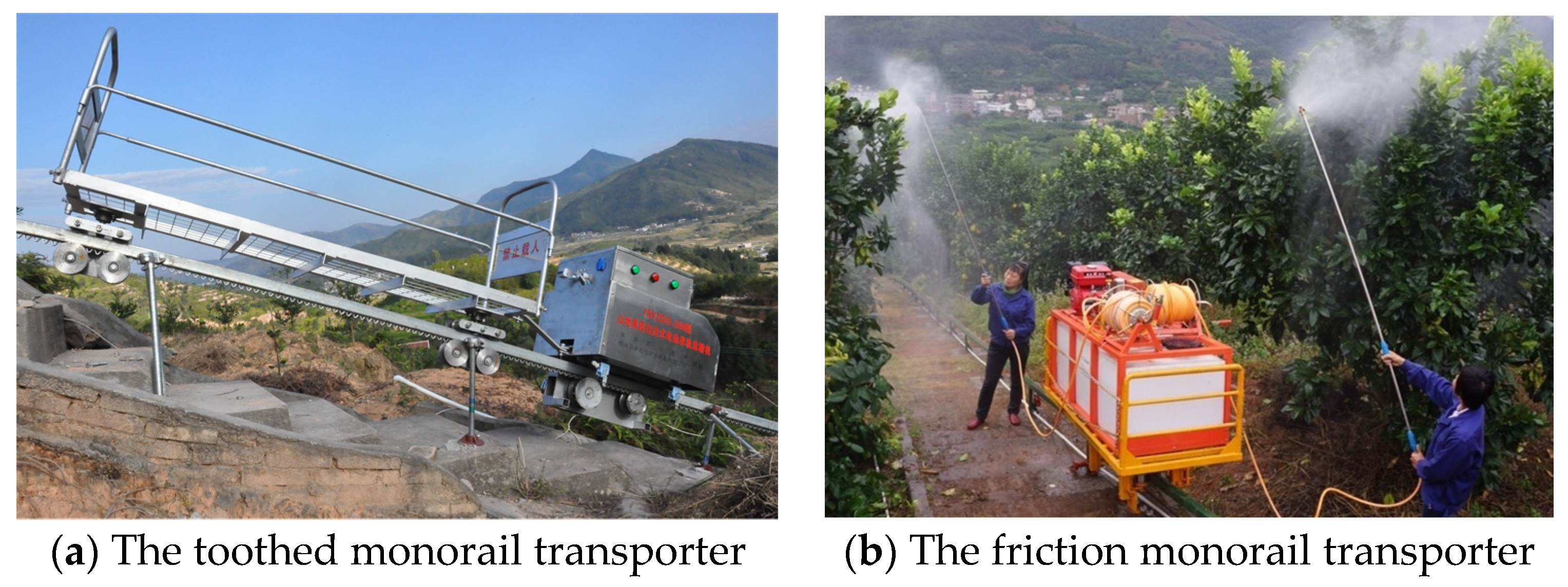
:1. Introduction
2. MRGTR Mechanism and Meshing Impact Vibration Analysis
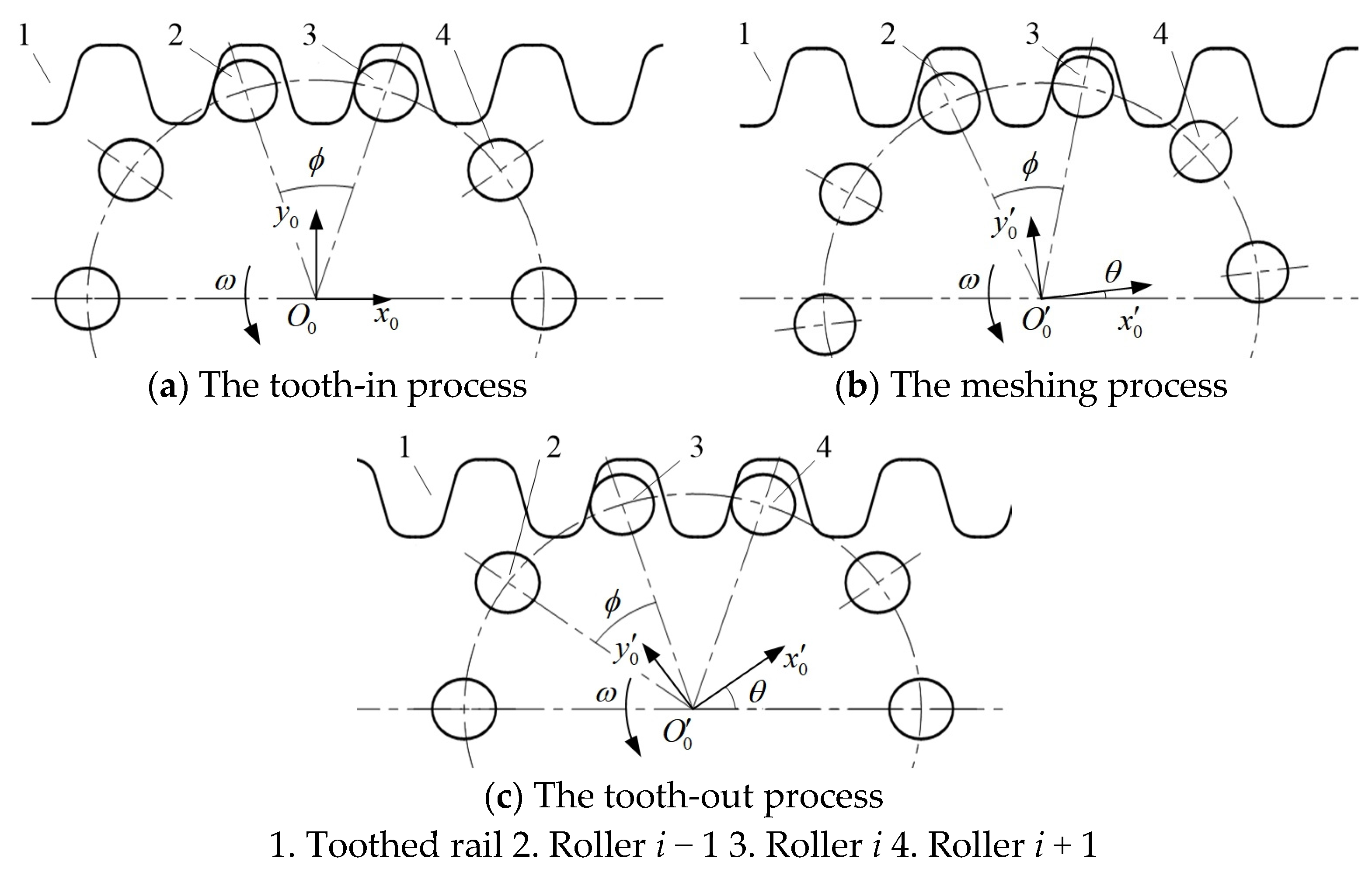
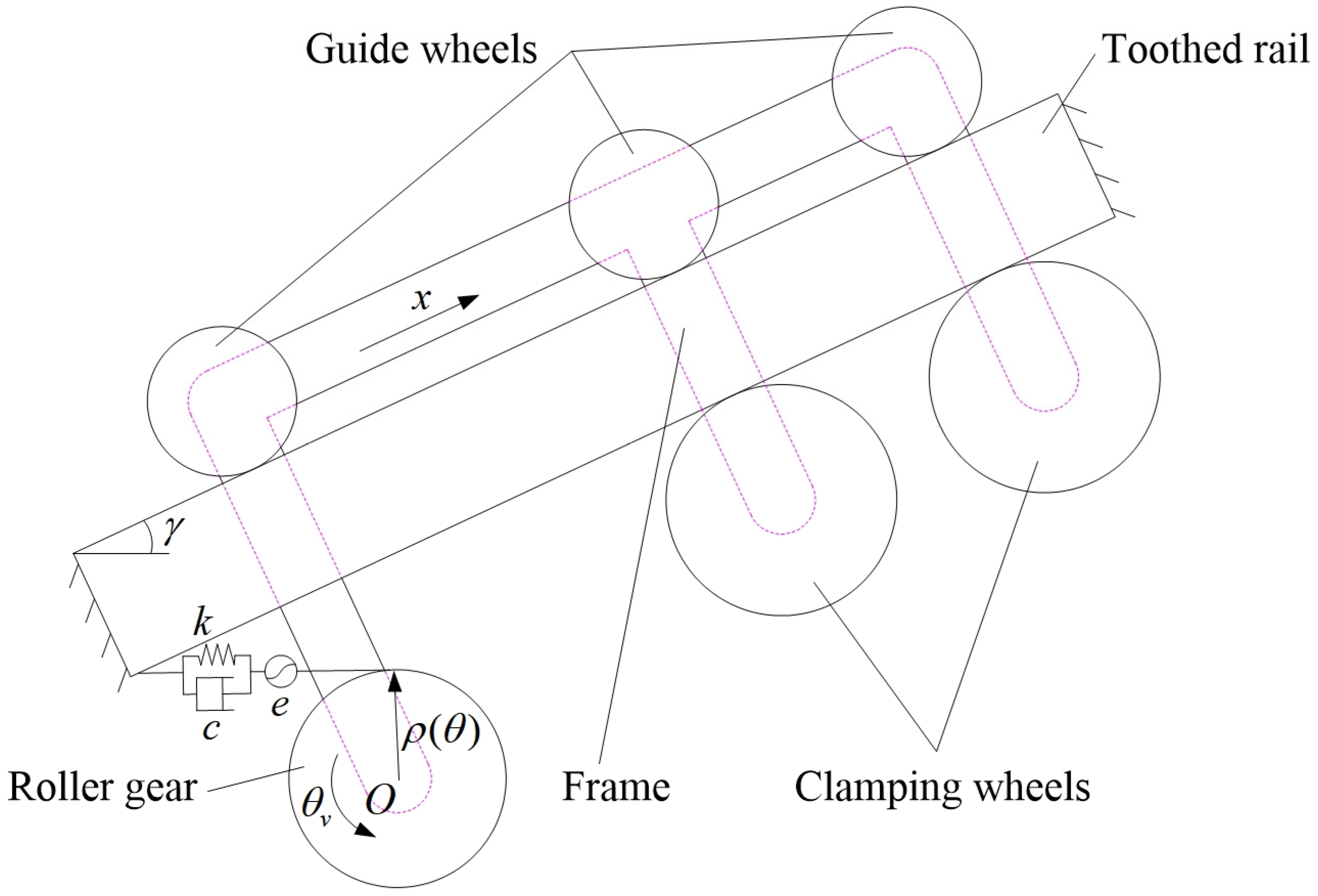
2.1. MRGTR Mechanism Analysis
2.1.1. Displacement Model of MSEMT
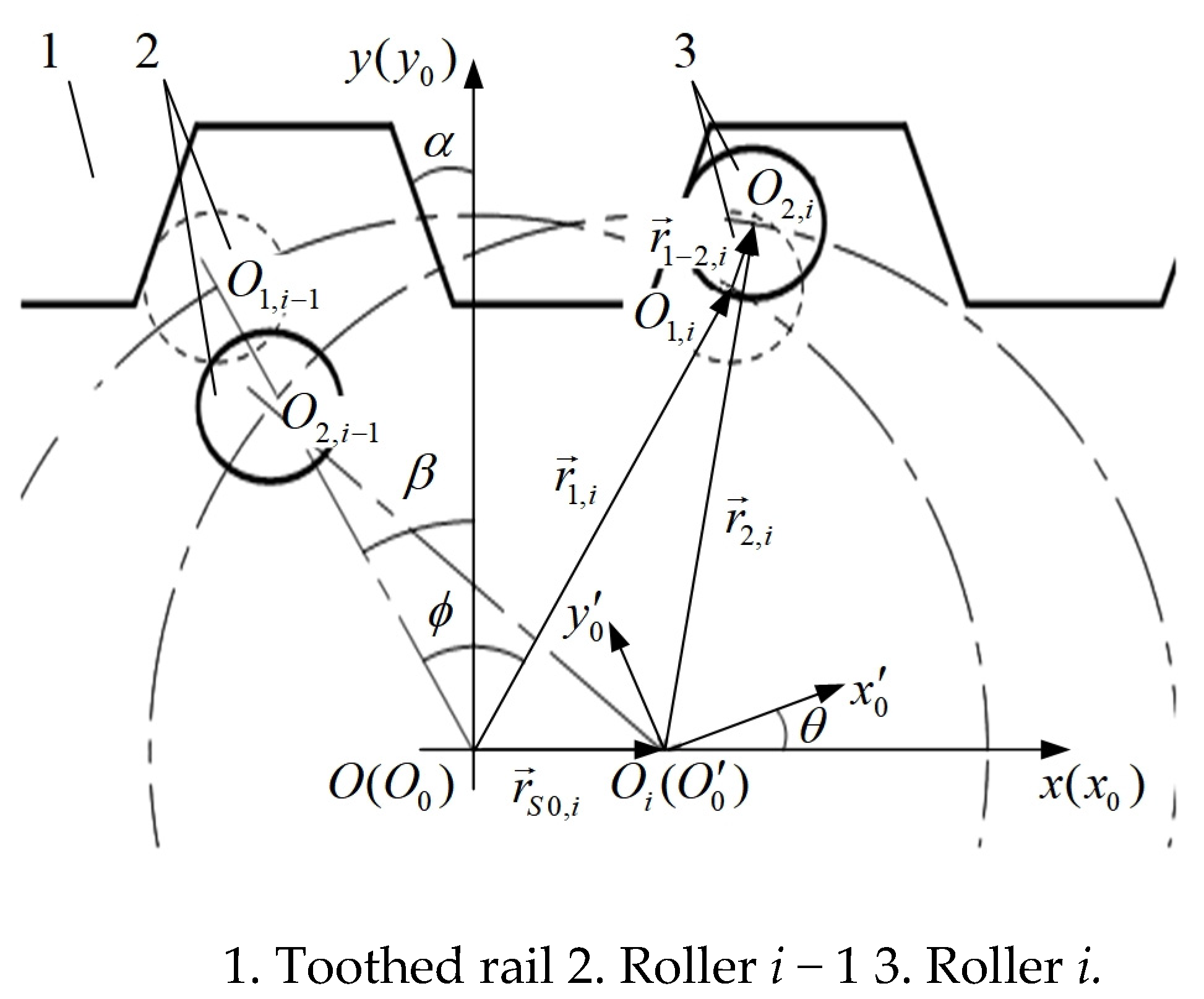
2.1.2. The Meshing Angle β at Initial Position
2.1.3. Instantaneous Velocity Model of MSEMT
2.2. MRGTR Impact Vibration
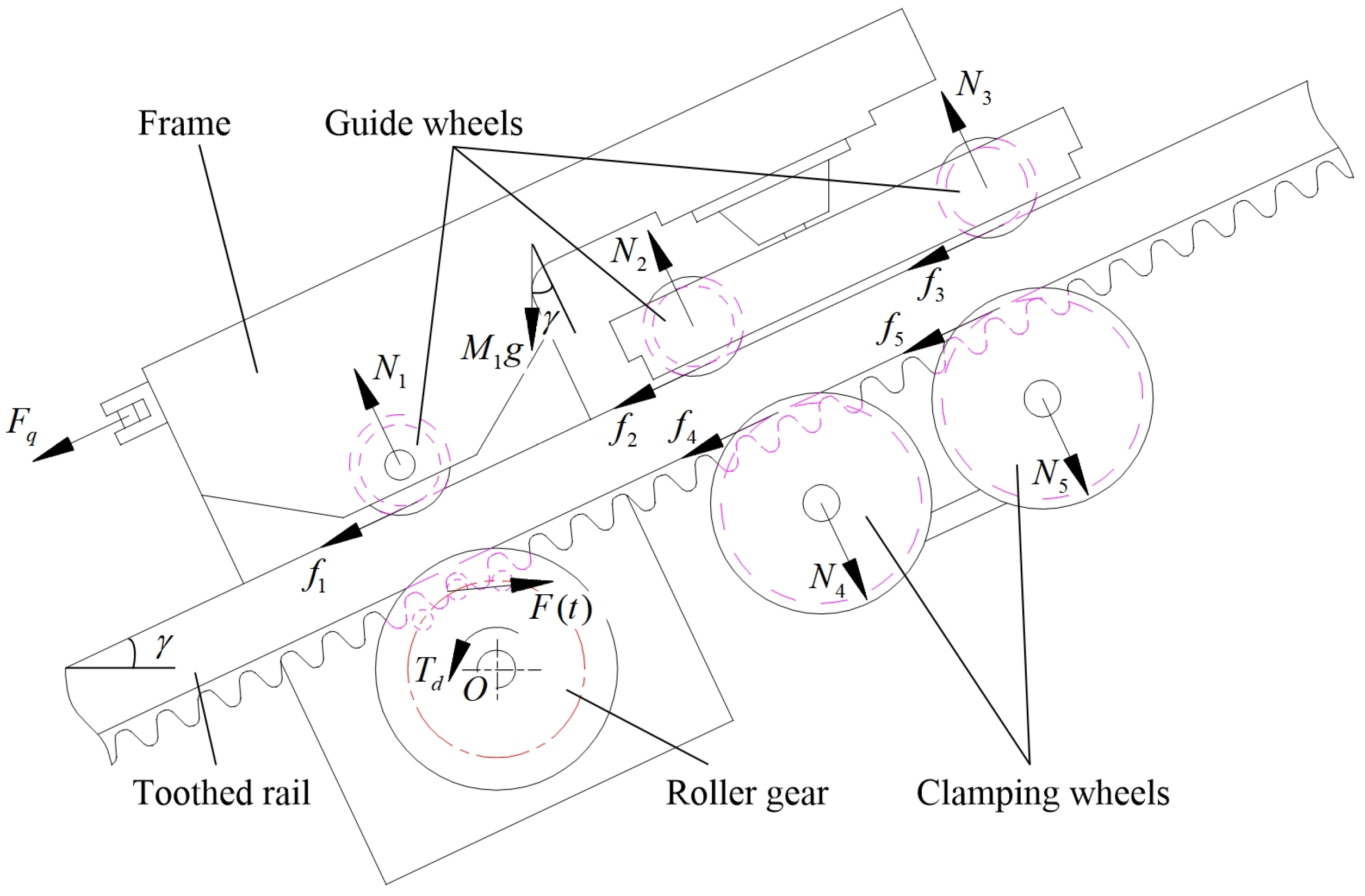
2.2.1. Force Analysis of the Driving Mechanism
2.2.2. Dynamic Model of Meshing Impact Vibration of MSEMT
2.2.3. Numerical Validation
3. Materials and Methods
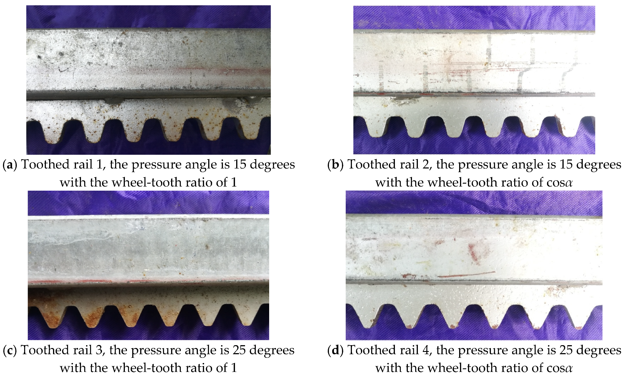
3.1. Test Material
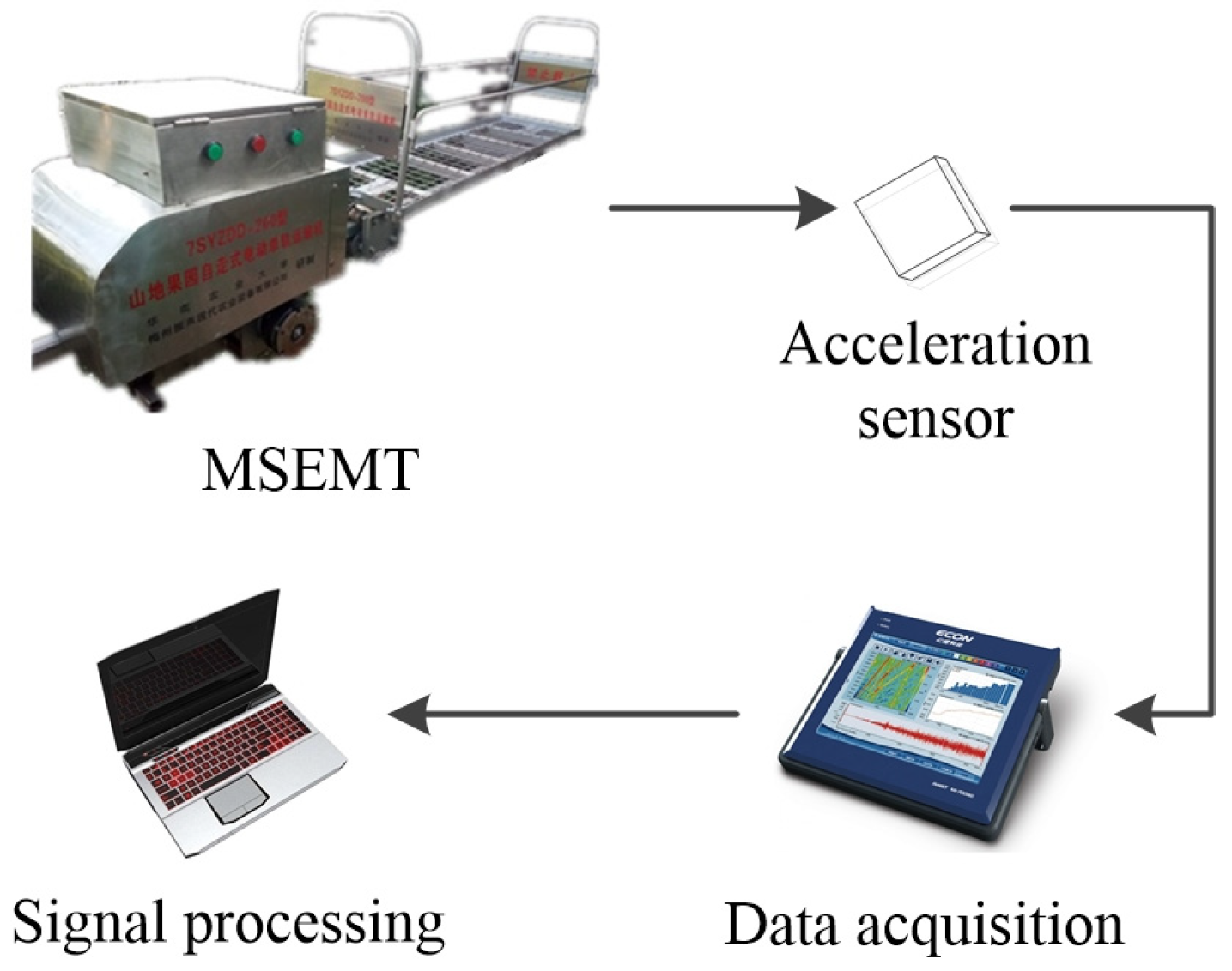
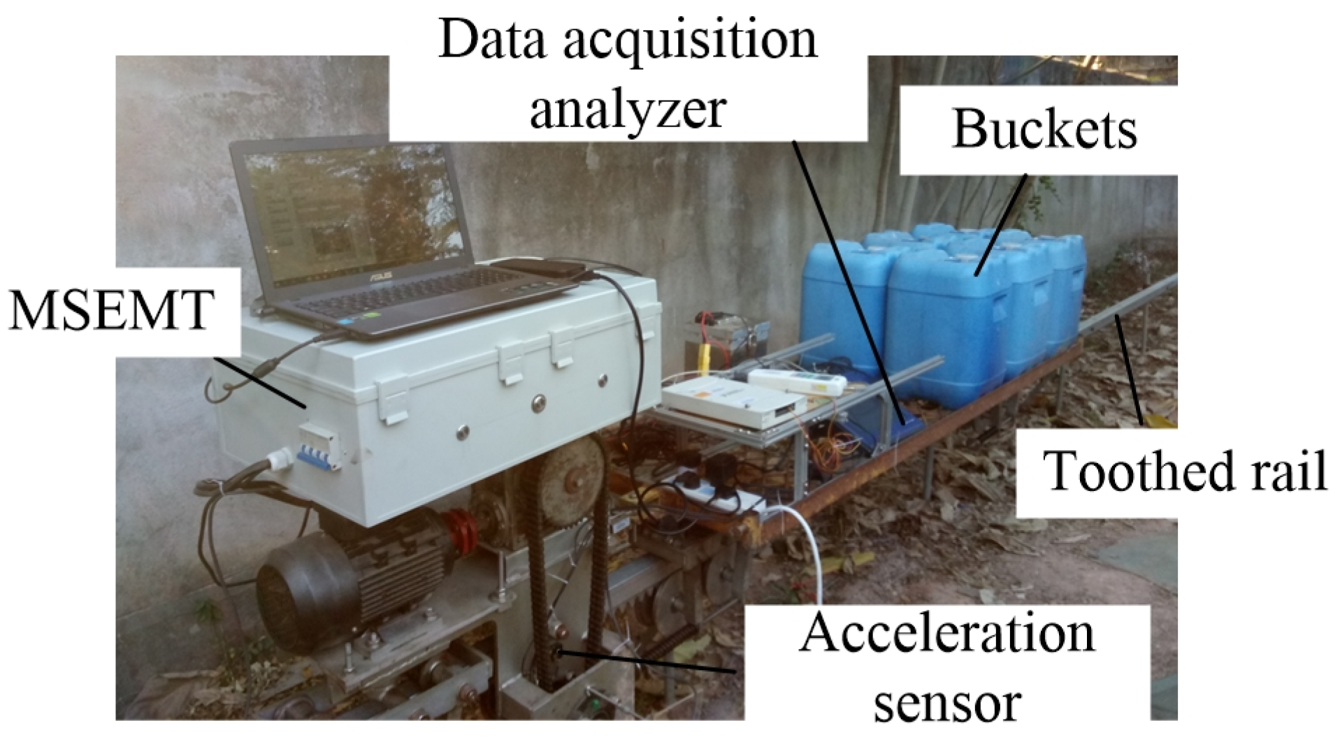
3.2. Test Platform and Equipment
3.3. Experiment Design
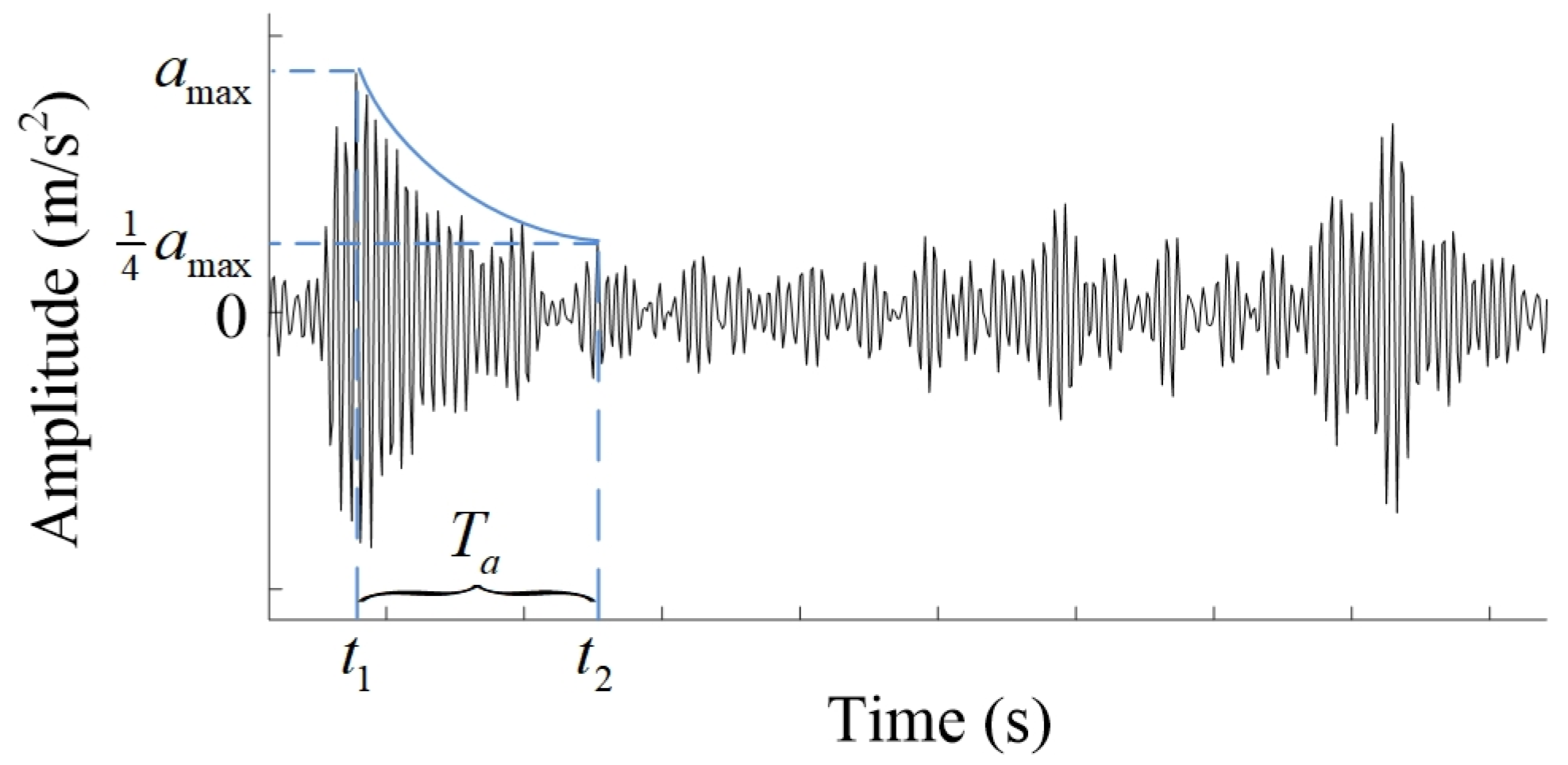
3.4. Evaluation and Calculation Method
4. Results and Analysis
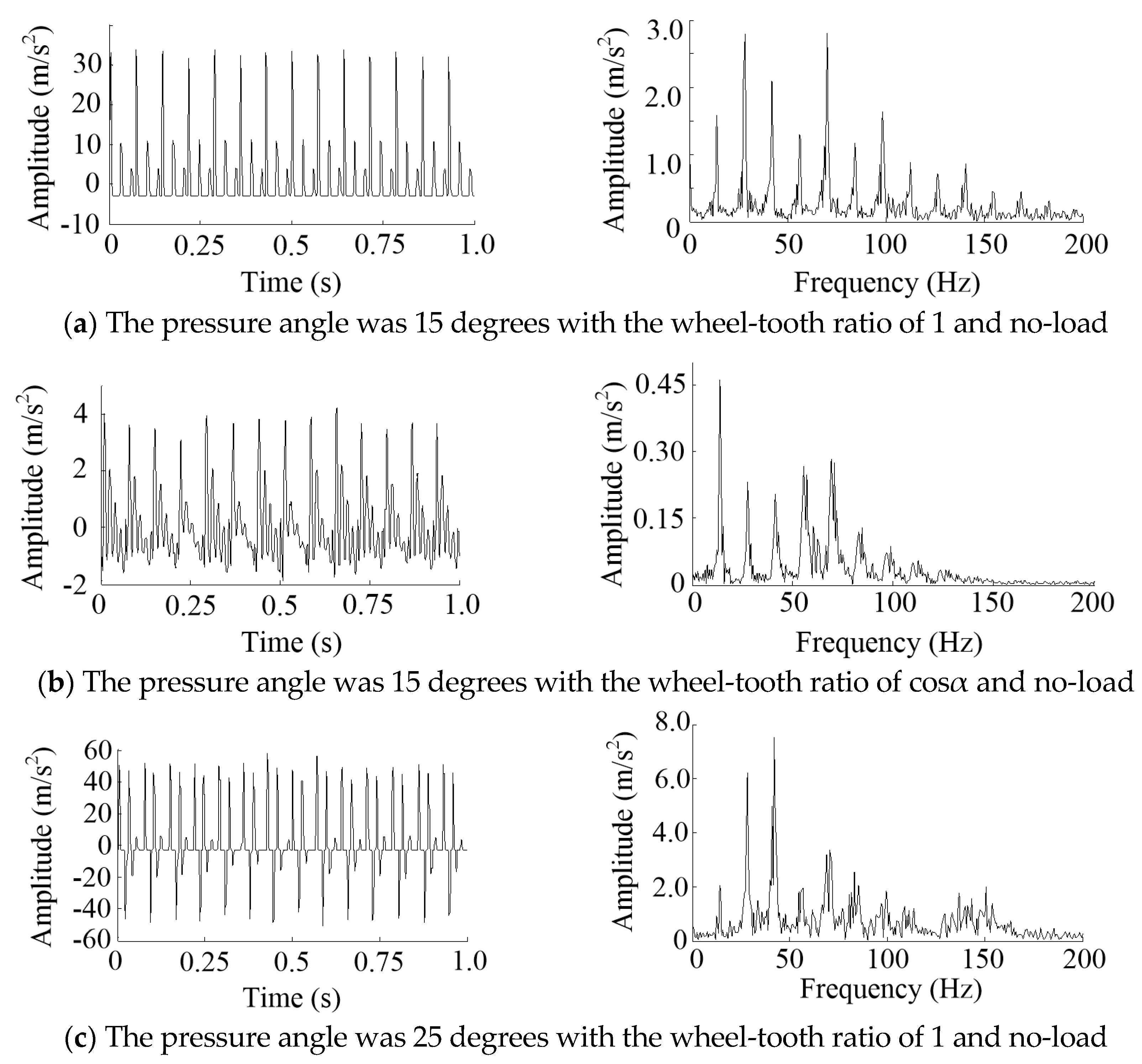
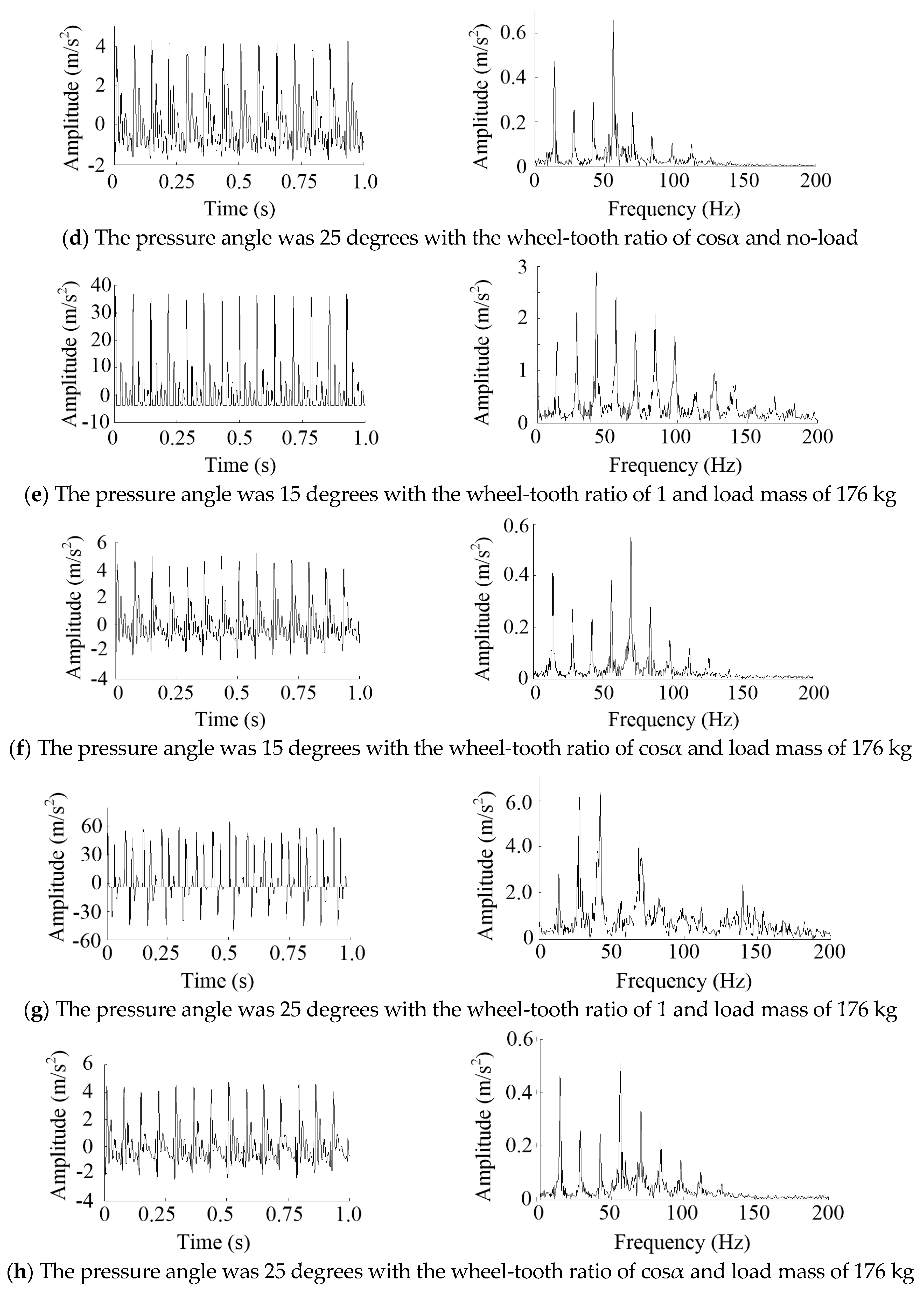
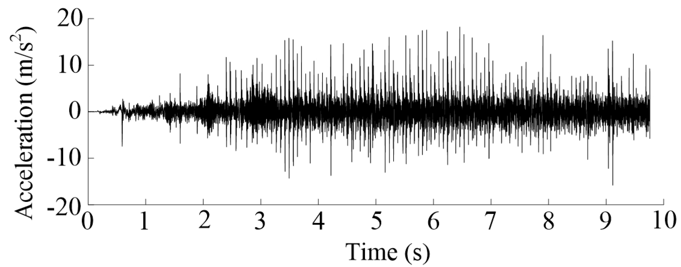
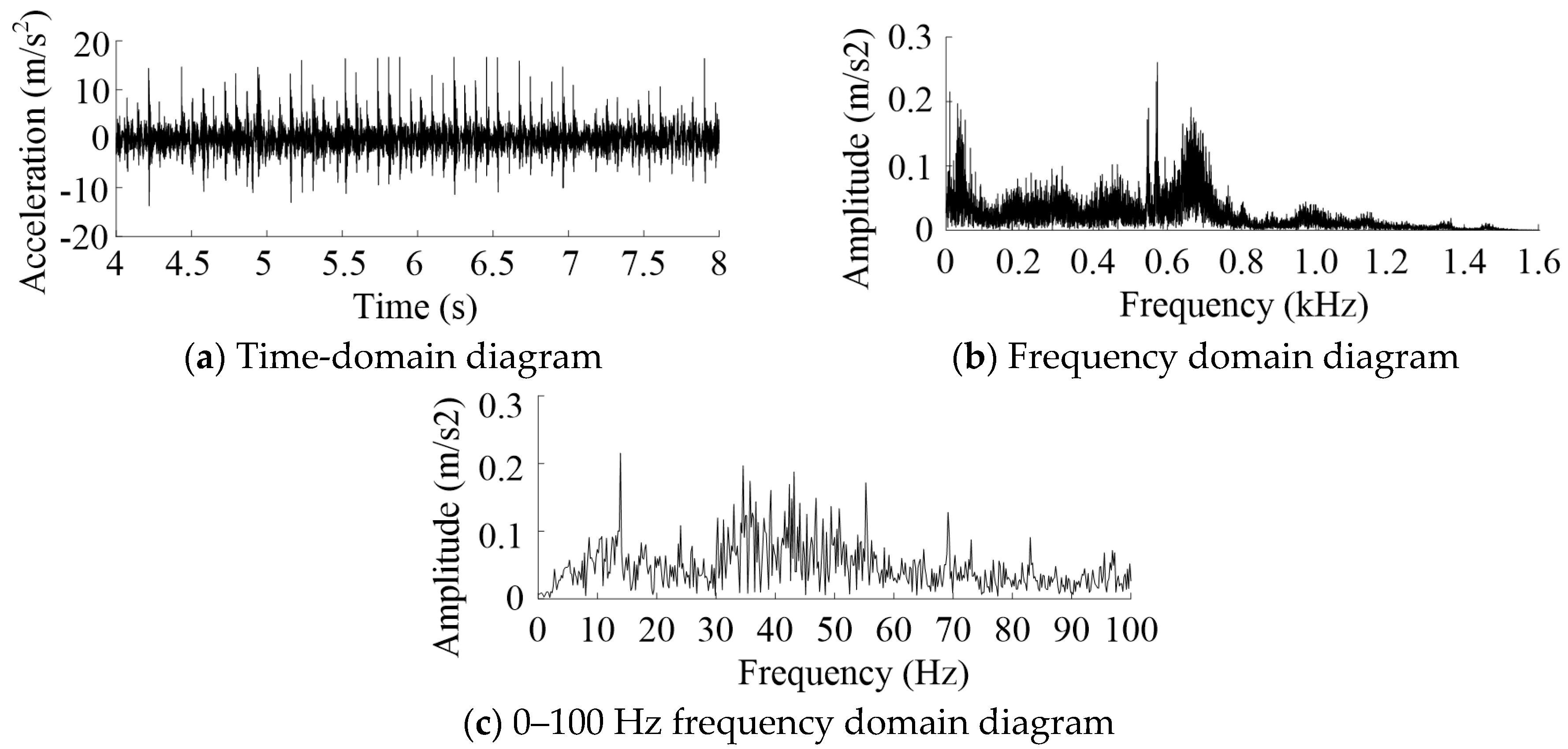
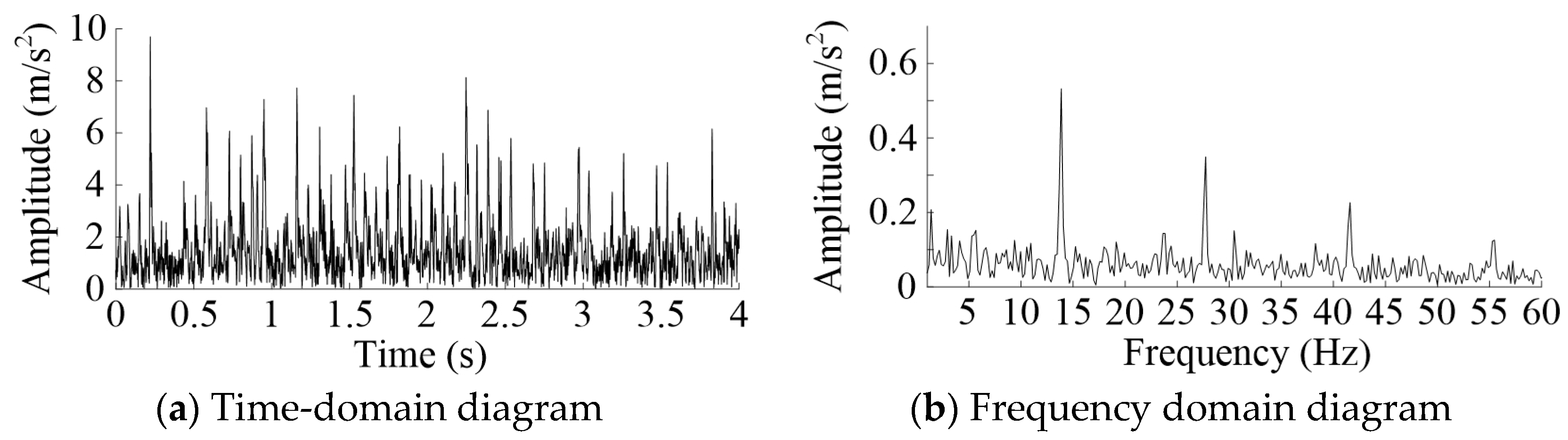
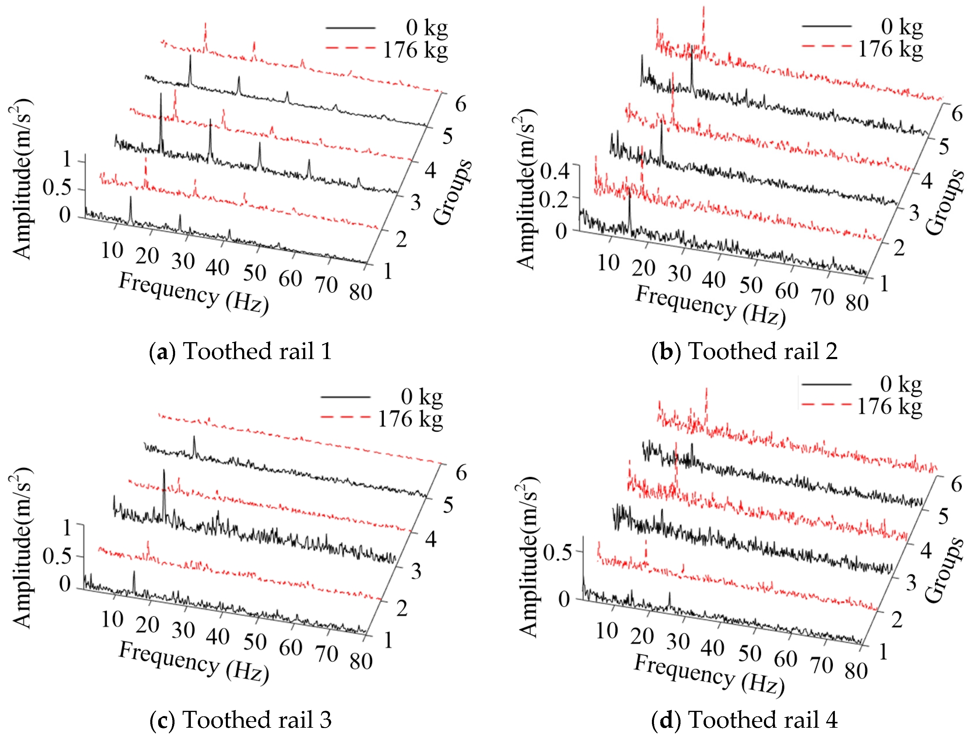
4.1. Processing and Analysis of Vibration Signal Results
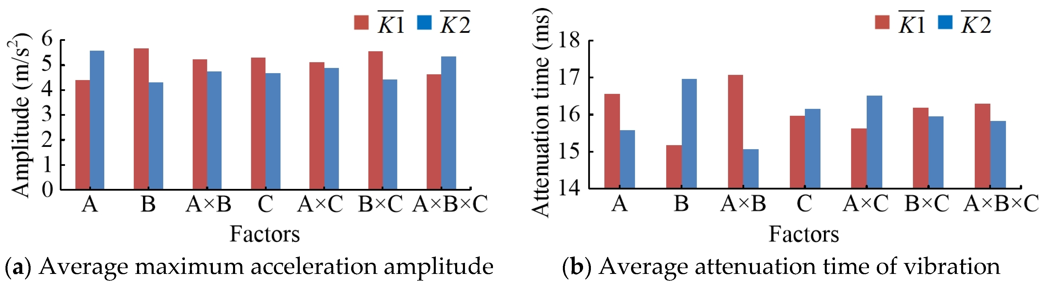
4.2. Orthogonal Test Results and Analysis
5. Conclusions
Author Contributions
Funding
Acknowledgments
Conflicts of Interest
References
- Rui, G.; Wei, Z.; Ya-feng, L.; Zhi-qiang, C.; Fan-yu, Z.; Ji-miao, Y. Progress in Research and Application of Forestry Rail Transporters in Hilly Areas. For. Mach. Woodwork. Equip. 2019, 47, 9–12. [Google Scholar]
- Morinaga, K.; Sumikawa, O.; Kawamoto, O.; Yoshikawa, H.; Nakao, S.; Shimazaki, M.; Kusaba, S.-N.-S.; Hoshi, N. New technologies and systems for high quality citrus fruit production, labor-saving and orchard construction in mountain areas of Japan. J. Mt. Sci. 2005, 2, 59–67. [Google Scholar] [CrossRef]
- Hui, L.; Shanjun, L.I.; Yanlin, Z.; Panyu, M.A.; Meng, C. Mechanical simulation and experiment of self-propelled monorail mountain orchard transporter under different racks. J. Huazhong Agric. Univ. 2019, 38, 114–122. [Google Scholar]
- Li, Z.; Xu, P.; Ouyang, Y.P.; Lv, S.L.; Dai, Q.F. Control System for the Mountainous Orchard Electric-Drive Monorail Transporter. Appl. Mech. Mater. 2015, 738, 935–940. [Google Scholar] [CrossRef]
- Yamamoto, S.; Kanamitsu, M.; Ajiki, K.; Fujiwara, M.; Tanaka, K. S-shaped Multipurpose Monorail for Hillside Orchards. Jpn. Agric. Res. Quart. JARQ 2007, 41, 147–152. [Google Scholar] [CrossRef] [Green Version]
- Jinkawa, M.; Yamaguch, H.; Furukawa, K.; Ouchi, A.; Hatano, T.; Satake, T.; Hourai, K. Development of a rail type logging machine with grapple crane. Jpn. For. Eng. Soc. 2008, 23, 141–148. [Google Scholar]
- Okazaki, K.; Miyazaki, M.; Nagasaki, Y.; Itokawa, N. Automation of Fram Work by an Overhead Monorail System in Steep Sloped Citrus Orchards. J. Jpn. Soc. Agr. Mach. 1996, 58, 103–109. [Google Scholar]
- Junfeng, Z.; Jingya, L.; Yanlin, Z.; Shanjun, L.; Liang, M. Design of Remote Control Monorail Transporter for Mountainous Orchard. Trans. Chin. Soc. Agr. Mach. 2012, 43, 90–95. [Google Scholar]
- Nakamura, K.; Okubo, K.; Fujii, T.; Uchida, S. Optimum Power Contribution Ratio of Two Pinion Gears Engaged with Rack Rail for Monorail Driven in Forest Industry. In Proceedings of the AASRI Winter International Conference on Engineering and Technology (AASRI-WIET 2013), Saipan, NP, USA, 28–29 December 2013; Atlantis Press: Saipan, NP, USA, 2013; pp. 33–37. [Google Scholar]
- Nagao, K.; Doshisha University; Okubo, K.; Fujii, T.; Uchida, S.; T.U.I.C Ltd. Reduction of Maximum Torque of Driving Shafts Concurrently Driven by Rubber V-belt for Monorail Traveling on Worn Rack Rail for Construction Uses. Int. J. Mater. Mech. Manuf. 2017, 5, 196–199. [Google Scholar] [CrossRef] [Green Version]
- Jinkawa, M.; Furukawa, K.; Satake, T.; Yamaguchi, H.; Kobayashi, H. Safety of the tram car for slopes examined by stress analysis of the ground structure. J. For. Res. 2006, 11, 77–88. [Google Scholar] [CrossRef]
- Shanjun, L.; Hui, L.; Yanlin, Z.; Hong, C.; Liang, M.; Panyu, M.; Chaoyu, Z.; Chi, Z. Optimization of rack tooth forms of monorail mountain orchard transporter. Trans. Chin. Soc. Agric. Eng. 2018, 34, 52–57. [Google Scholar]
- Zhang, K. Driving Performance of Rubber Roller on A Friction Orchard Conveyor Based on Finite Element Method. Ph.D. Thesis, Huazhong Agricultural University, Wuhan, China, 2013. [Google Scholar]
- Wang, F.; De Fang, Z.; Li, S.J. Nonlinear Dynamic Analysis of Helical Gear Considering Meshing Impact. Appl. Mech. Mater. 2012, 135–138. [Google Scholar] [CrossRef]
- Honda, H.; Makino, H. Research on the Trochoidal Gears (1st Report)—Classification and Basic Formulas of the Trochoidal Gears. J. Jpn. Soc. Precis. Eng. 1994, 60, 949–953. [Google Scholar] [CrossRef] [Green Version]
- Honda, H. Research on the Trochoidal Gears (2nd Report)—Pressure Angle of Trochoidal Gears and Modification of Tooth Profile. J. Jpn. Soc. Precis. Eng. 1995, 61, 208–212. [Google Scholar] [CrossRef] [Green Version]
- Zhang, D.; Hu, S.H.; Liu, C.S.; Liu, X.T. Modeling and Kinematics Simulation of Shearer’s Travelling Mechanism Based on Virtual Prototyping Technology. Adv. Mater. Res. 2013, 655, 396–399. [Google Scholar] [CrossRef]
- Ishida, K.; Terada, H.; Furuya, N.; Makino, H.; Imase, K. Fundamental Analysis of Linear Type Trochoidal Gear. (2nd Report). Motion Principle for Roller Rack Type Trochoidal Gear. J. Jpn. Soc. Precis. Eng. 1999, 65, 428–432. [Google Scholar] [CrossRef] [Green Version]
- Terada, H.; Ishida, K.; Chiba, H.; Imase, K. Fundamental Analysis of a Linear Type Trochoidal Gear (3rd Report)—Kinematic Analysis of an Internal Gear Type Trochoidal Comer Curve Rack. J. Jpn. Soc. Precis. Eng. 2004, 70, 209–213. [Google Scholar]
- Soon-man, K. Tooth Root Bending Stress of Roller-Rack and Pinion System. J. Korean Soc. Manuf. Tech. Eng. 2018, 27, 492–498. [Google Scholar]
- Kim, C.-H.; Choi, H.-S.; Kwon, S.-M. Contact surface fatigue life for roller rack pinion system. J. Central South Univ. 2012, 19, 3454–3459. [Google Scholar] [CrossRef]
- Kim, C.-H.; Nam, H.-C.; Kwon, S.-M. Pitting Life of CRP System. J. Korean Soc. Manuf. Technol. Eng. 2012, 21, 283–289. [Google Scholar] [CrossRef] [Green Version]
- Litvin, F.; Lu, J. Computerized simulation of generation, meshing and contact of double circular-arc helical gears. Math. Comput. Model. 1993, 18, 31–47. [Google Scholar] [CrossRef]
- Yang, D.C.H.; Lin, J.Y. Hertzian Damping, Tooth Friction and Bending Elasticity in Gear Impact Dynamics. J. Mech. Transm. Autom. Des. 1987, 109, 189–196. [Google Scholar] [CrossRef]
- Wojnarowski, J.; Onishchenko, V. Tooth wear effects on spur gear dynamics. Mech. Mach. Theory 2003, 38, 161–178. [Google Scholar] [CrossRef]
- Kahraman, A.; Singh, R. Non-linear dynamics of a spur gear pair. J. Sound Vib. 1990, 142, 49–75. [Google Scholar] [CrossRef]
- Runfang, L.; Jianjun, W. Dynamic of Gear System—Vibration, Impact and Noise, 1st ed.; Science Press: Beijing, China, 1997; pp. 121–161. [Google Scholar]
- Zuoqin, Z.; Xuezhi, Z. Study about the effect of meshing stiffness and meshing damping on gear vibration. Mach. Tool Hydraul. 2010, 5, 32–34. [Google Scholar]
- Wen, B. Machine Design Handbook, 5th ed.; China Machine Press: Beijing, China, 2010; Volume 2, pp. 810–812. [Google Scholar]
- Yunyan, L.; Chuanrong, H. Experimental Design and Data Processing, 1st ed.; Chemical Industry Press: Beijing, China, 2008; pp. 164–180. [Google Scholar]
- Borghesani, P.; Pennacchi, P.; Chatterton, S. The relationship between kurtosis- and envelope-based indexes for the diagnostic of rolling element bearings. Mech. Syst. Signal Process. 2014, 43, 25–43. [Google Scholar] [CrossRef]
- Djebala, A.; Ouelaa, N.; Benchaabane, C.; Laefer, D.F. Application of the Wavelet Multi-resolution Analysis and Hilbert transform for the prediction of gear tooth defects. Meccanica 2012, 47, 1601–1612. [Google Scholar] [CrossRef] [Green Version]


| Parameter | Toothed Rail 1 | Toothed Rail 2 | Toothed Rail 3 | Toothed Rail 4 |
|---|---|---|---|---|
| Pressure Angle α (°) | 15 | 15 | 25 | 25 |
| Pitch p (mm) | 30.9 | 31.99 | 30.9 | 34.09 |
| Wheel-tooth ratio | 1 | cosα | 1 | cosα |
| Height of tooth hf (mm) | 35.5 | 35.5 | 35.5 | 35.5 |
| Parameter | Numerical |
|---|---|
| Empty mass of MSEMT M0 (kg) | 175 |
| The rated speed of motor n (r/min) | 1500 |
| Transmission ratio i | 17.143 |
| Roller gear rotational speed nr (r/min) | 81.67~93.33 |
| Given speed vd (m/min) | 25.65~29.32 |
| Number of rollers z | 10 |
| Radius of the central circle of roller R (mm) | 50 |
| Radius of roller r (mm) | 7 |
| Levels | Factor A | Factor B | Factor C |
|---|---|---|---|
| Pressure Angle α (°) | Wheel-Tooth Ratio | Load Mass M2 (kg) | |
| 1 | 15 | 1 | 0 |
| 2 | 25 | cosα | 176 |
| Type | Load Mass (kg) | Peak Frequency (Hz) | Amplitude (m/s2) | Average Peak Frequency (Hz) | Average Amplitude (m/s2) | ||||
|---|---|---|---|---|---|---|---|---|---|
| Group 1 | Group 2 | Group 3 | Group 1 | Group 2 | Group 3 | ||||
| Toothed rail 1 | 0 | 13.87 | 13.87 | 13.87 | 0.5321 | 0.6117 | 1.1530 | 13.87 | 0.7656 |
| 27.73 | 27.73 | 27.73 | 0.3490 | 0.3619 | 0.8353 | 27.73 | 0.5154 | ||
| 41.6 | 41.6 | 41.6 | 0.2264 | 0.2679 | 0.5619 | 41.6 | 0.3521 | ||
| 55.47 | 55.47 | 55.47 | 0.1258 | 0.1354 | 0.3972 | 55.47 | 0.2195 | ||
| 176 | 13.67 | 13.67 | 13.67 | 0.5974 | 0.6102 | 0.5691 | 13.67 | 0.5922 | |
| 27.34 | 27.34 | 27.34 | 0.3838 | 0.3684 | 0.3977 | 27.34 | 0.3833 | ||
| 41.02 | 41.02 | 41.02 | 0.2602 | 0.2355 | 0.2216 | 41.02 | 0.2391 | ||
| 54.69 | 54.69 | 54.69 | 0.1459 | 0.1459 | 0.1398 | 54.69 | 0.1439 | ||
| 68.36 | 68.36 | 68.36 | 0.1196 | 0.0966 | 0.1080 | 68.36 | 0.1081 | ||
| Toothed rail 2 | 0 | 14.84 | 15.23 | 15.04 | 0.3093 | 0.3013 | 0.3325 | 15.04 | 0.3144 |
| 176 | 14.06 | 14.06 | 14.06 | 0.3641 | 0.3762 | 0.3594 | 14.06 | 0.3666 | |
| Toothed rail 3 | 0 | 15.23 | 15.04 | 15.04 | 0.4167 | 0.9276 | 0.3825 | 15.10 | 0.5756 |
| 27.54 | 30.27 | 30.27 | 0.2227 | 0.4285 | 0.1517 | 29.36 | 0.2676 | ||
| 176 | 14.84 | 15.04 | 15.04 | 0.3438 | 0.2682 | 0.1348 | 14.65 | 0.2489 | |
| 29.78 | 25.78 | 28.91 | 0.1597 | 0.1652 | 0.0626 | 28.16 | 0.1291 | ||
| Toothed rail 4 | 0 | 14.84 | 15.04 | 15.04 | 0.1911 | 0.3277 | 0.2997 | 14.97 | 0.2728 |
| 25.59 | 28.52 | 32.03 | 0.2288 | 0.2224 | 0.1430 | 28.71 | 0.1981 | ||
| 176 | 14.65 | 14.65 | 14.84 | 0.3534 | 0.6664 | 0.533 | 14.71 | 0.5176 | |
| No. | Factors | |||||||
| A Pressure angle | B Wheel-tooth ratio | A×B Interaction of pressure angle and wheel-tooth ratio | C Load mass | A×C Interaction of pressure angle and load mass | B×C Interaction of wheel-tooth ratio and load mass | A×B×C Interaction of pressure angle, wheel-tooth ratio and load mass | ||
| 1 | 1 | 1 | 1 | 1 | 1 | 1 | 1 | |
| 2 | 1 | 1 | 1 | 2 | 2 | 2 | 2 | |
| 3 | 1 | 2 | 2 | 1 | 1 | 2 | 2 | |
| 4 | 1 | 2 | 2 | 2 | 2 | 1 | 1 | |
| 5 | 2 | 1 | 2 | 1 | 2 | 1 | 2 | |
| 6 | 2 | 1 | 2 | 2 | 1 | 2 | 1 | |
| 7 | 2 | 2 | 1 | 1 | 2 | 2 | 1 | |
| 8 | 2 | 2 | 1 | 2 | 1 | 1 | 2 | |
| No. | Indicators | |||||||
| Average maximum acceleration amplitude (m/s2) | Average attenuation time of the vibration (ms) | |||||||
| 1 | 5.9701 | 16.4678 | ||||||
| 2 | 4.6906 | 16.8427 | ||||||
| 3 | 3.7128 | 15.5683 | ||||||
| 4 | 3.2553 | 17.3349 | ||||||
| 5 | 7.1488 | 13.9068 | ||||||
| 6 | 4.9058 | 13.4467 | ||||||
| 7 | 4.4201 | 17.9550 | ||||||
| 8 | 5.8806 | 17.0068 | ||||||
| Analysis | Average Maximum Acceleration Amplitude (m/s2) | Average Attenuation Time of the Vibration (ms) | ||||||
|---|---|---|---|---|---|---|---|---|
| B | A | B×C | A×B×C | A×B | B | A | A×C | |
| SS | 3.708 | 2.792 | 2.560 | 1.038 | 8.031 | 6.482 | 1.900 | 1.575 |
| df | 1 | 1 | 1 | 1 | 1 | 1 | 1 | 1 |
| MS | 3.708 | 2.792 | 2.560 | 1.038 | 8.031 | 6.482 | 1.900 | 1.575 |
| F | 8.077 | 6.083 | 5.577 | 2.261 | 39.435 | 31.827 | 9.328 | 7.734 |
| Sig. | 0.066 | 0.090 | 0.099 | 0.230 | 0.008 | 0.011 | 0.055 | 0.069 |
| significance | * | * | * | ** | ** | * | * | |
Publisher’s Note: MDPI stays neutral with regard to jurisdictional claims in published maps and institutional affiliations. |
© 2020 by the authors. Licensee MDPI, Basel, Switzerland. This article is an open access article distributed under the terms and conditions of the Creative Commons Attribution (CC BY) license (http://creativecommons.org/licenses/by/4.0/).
Share and Cite
Liu, Y.; Hong, T.; Li, Z. Influence of Toothed Rail Parameters on Impact Vibration Meshing of Mountainous Self-Propelled Electric Monorail Transporter. Sensors 2020, 20, 5880. https://doi.org/10.3390/s20205880
Liu Y, Hong T, Li Z. Influence of Toothed Rail Parameters on Impact Vibration Meshing of Mountainous Self-Propelled Electric Monorail Transporter. Sensors. 2020; 20(20):5880. https://doi.org/10.3390/s20205880
Chicago/Turabian StyleLiu, Yue, Tiansheng Hong, and Zhen Li. 2020. "Influence of Toothed Rail Parameters on Impact Vibration Meshing of Mountainous Self-Propelled Electric Monorail Transporter" Sensors 20, no. 20: 5880. https://doi.org/10.3390/s20205880