1. Introduction
The legged machine shows its excellent adaptability of negotiating the convex obstacles. However, these actions necessitate substantial planning calculation [
1], complicated model to sustain walking stability while swinging foot [
2,
3], and obstacle with a flat surface and relatively low height to maintain foothold safety [
4]. As legged robots have been developing to become popular, there is growing interest in incorporating benefits from the wheeled and legged mechanism to realize hybrid locomotion, intensifying the intention of boosting mobility and efficiency. Several wheel-legged hybrid robots (WLHRs) have shown their ability of adapting to convex environment. The robot CENTAURO [
5] which are equipped with steerable wheels on legs’ ending allows for executing steps, omnidirectional steering, and dominating a large variety of mobile manipulation missions, demonstrating its various moving modes in different types of terrains.
Within the correlative application territory, obstacle negotiation has extensively involved several aspects among mobile robots, under the priority optimizing the robot stability and trajectory smoothness. With sustaining walking stability and kinematic feasibility, Yue [
6] adopted the concept of artificial potential field on a hexapod robot to avoid obstacles. A novel obstacle avoidance method [
7], Follow the Gap Method, eliminated local minimum problem in path planning on an autonomous ground vehicle with Ackermann steering geometry. The collision-free paths [
8] were planned using probabilistic roadmaps targeting on a given location. A laser-based people tracking component estimated the motions of humans. Guaranteeing smoothness and collision-free, a reciprocal orientation algorithm [
9] planned trajectories for multi-robot without direct communication with other robots. With the assumption of flat terrain, an optimal global path was planned [
10]. Connecting states through local trajectory generator is set up as a graph-search problem, which is solved by best-first search. Furthermore, a precise tracking controller is also important for underactuated systems especially with unknown parameters and disturbances. Adaptive neural networks [
11] approximated unknown dynamics and updated parameters to decrease tracking error.
To autonomously drive in different environment, specific terrain description can effectively enhance robot shifting availability. The hierarchical data structure [
12] identified and stored obstacle cells as non-uniform
trees, which is crucial before planning. The surface normals [
13] on robot-centric elevation map are employed to select feasible footholds, organizing collision-free trajectories for swing feet. The planar laser scan, stereo vision, and preoperative sensing mounted on BigDog robot transformed data collection into a 2D cost representation. BigDog [
14] equipped with a combination of planar laser scans, stereo vision, and preoperative sensing to perceive obstacles and placed their data collection into a 2D cost representation. Then it planed paths through a variation classic A* search and steered four legs to follow them. The Messor II hexapod [
15] employed RGB-D data to combine OctoMap and elevation grid into a 3-D semantic labeling of natural environments, conducting its motion planning. Establishing a bridge between discrete and continuous planning primitively [
16] leveraged each individual configuration of ground contact points (footholds) in legged locomotion which are explored to forge specified motion sequences to avoid collision without compromising COM agility. However, none of these approaches concentrated on obstacle avoidance for robot body and reconfigured relationship between limbs, which is independent in narrow space.
As for the planning algorithm for configurable robots or executing obstacle negotiation through changing arrangement between different robot components, have been implemented in several kinds of robots. Combining with point clouds segmentation and traversability analysis, an autonomous 3D path planning [
17] executed rolling motion using a tracked reconfigurable vehicles on stairway and slope. Maximising the height of sensor payload, stability [
18] and moving capability [
19] originated from A* search to enhance on uneven terrain. Anh [
20] advanced an efficient coverage path planning in a novel self-reconfigurable cleaning robot. A modified A-Star zigzag global planner can generate waypoints for the purpose of maximizing robot’s coverage area. A reconfigurable snake-like robot [
21] integrated path and motion planning approach to move in challenging environments populated with obstacles like stairs. The terrain information used for motion planning is presented by a multi-resolution map. Then an extended RRT* is utilized to form a multi-layered planning model, generating a multi-stepped planning process. In Reference [
22], a contact dynamic rodmaps is constructed, which generates discretized motions in each leg’s workspaces offline. Then a mapping method is designed to obtain motions in its configuration space. In the online phase, the planner can adapt to environment rapidly and generate collision-free foothold positions. In Reference [
23], to acquire multifaceted navigation skill such as body slimming or lifting for obstacle avoidance, an end-to-end planning method based on deep reinforcement learning is presented, which generates motor commands directly from the height map. Furthermore, a multi-modal PRM is proposed in Reference [
24] for planning problems with finite number of intersecting manifolds. It applied to determine support polygons and configurations of ATHLETE and HRP2 robot walking on flat, stairs, and undulating terrains. The convergence of an incremental variant of PRM was also proved. A wheel-legged hybrid locomotion was also executed on the ATHLETE robot simulation, but the calculation quantity of mentioned planner is considerably abundant when obstacle avoidance did not involve. The pattern of wheel-legged hybrid locomotion involves not only the driving-stepping but also the foothold polygon adaptive locomotion. MOMARO robot parameterized the stepping and driving locomotion into a single ARA* planner [
25] and combined three-level abstract traversing manoeuvres [
26] on stairs. Furthermore, the Value Iteration Networks (VINs) [
27] planed omnidirectional driving for support polygon obstacle avoidance in cluttered terrain that combined multiple levels of abstraction. The computational cost of these planner are expensive or highly dependented on number of robot joints or offline training.
Intuitively, the obstacle negotiation issue for robot in confined space can be simplified as a deformable bounding box abstraction of robot model, which is inspired from reconfigurable and soft robots. The Randomized Possibility Graphs [
28] combined the bounding boxes attached to biped robot to rapidly explore the possible actions in a variety of semi-unstructured environments. The nested robot [
29] was utilized to gradually induce number of abstract models, which is called the Quotient-space roadMap Planner to search action graph until a valid path had been found. A hexapod robot Weaver [
30] has the ability to adapt walking posture to tunnel environment, in which the scheduled method smoothed trajectories by Covariant Hamiltonian Optimization for Motion Planning (CHOMP) [
31] for Efficient Motion Planning. The CENTAURO robot [
32] transformed the Octomap into 2D occupation map to determine robot polygon shrinking and expansion to go over obstacles through traditional A* search program.
WLHR inherits the compounded superiority, including flexible obstacle-crossing function, efficiency, and agility from legged and wheeled systems. Compared to common serial leg mechanism, Stewart parallel counterpart holds higher load capacity and permits six-dimensional movability in the narrower zone, which generally creates omnidirectional movement and adjustable volume deformation on a rigid and mix-and-match manner of wheels and feet robot. There have been some researches concerning grid-searched algorithm for stepping-driving hybrid locomotion [
25,
26] and changeable foothold polygon [
32] on two-dimensional planning to traverse obstacles, but no optimization-based composition for WLHR in three-dimensional obstacle avoidance. The BIT-NAZA robot is able to roll towards arbitrary orientation without rotating body configuration as well as adaptable trunk height and foothold polygon, which is immensely suitable constituting a rigid deformable robot. The covariant gradient optimization devotes to identify a collision-free trajectory, even when the initial trajectory contained many collisions. Actually, the proposed strategy initiates BIT-NAZA WLHR to change the wheel-legged configuration, bringing different kinds of foothold polygon into existence while in a rolling motion. To our best knowledge, this is the first time that incorporates bounding box abstraction and covariant gradient optimization algorithm to design a numerical solver on a rigid object which is also a WLHR regarded as a deformable robot. In this case, the robot is capable of independently navigating in confined spaces via morphing configuration, negotiating certain obstacles. We suppress crash between each element on the morphing geometry and obstacles in confined space since whether the crash can happen relates to the signed distance field (SDF) whose array is calculated from a robot-centric obstacle information. Succinctly, our main contribution can be enumerated as follows:
Present and fabricate a novel WLHR prototype with Stewart parallel mechanism. The parallel structure enable robot to afford more than 300 kg burden. The full software and hardware layouts are exhibited from an individual electric motor controller to perception sensor mapper, contributing to expose how the intricate system work from low to high level.
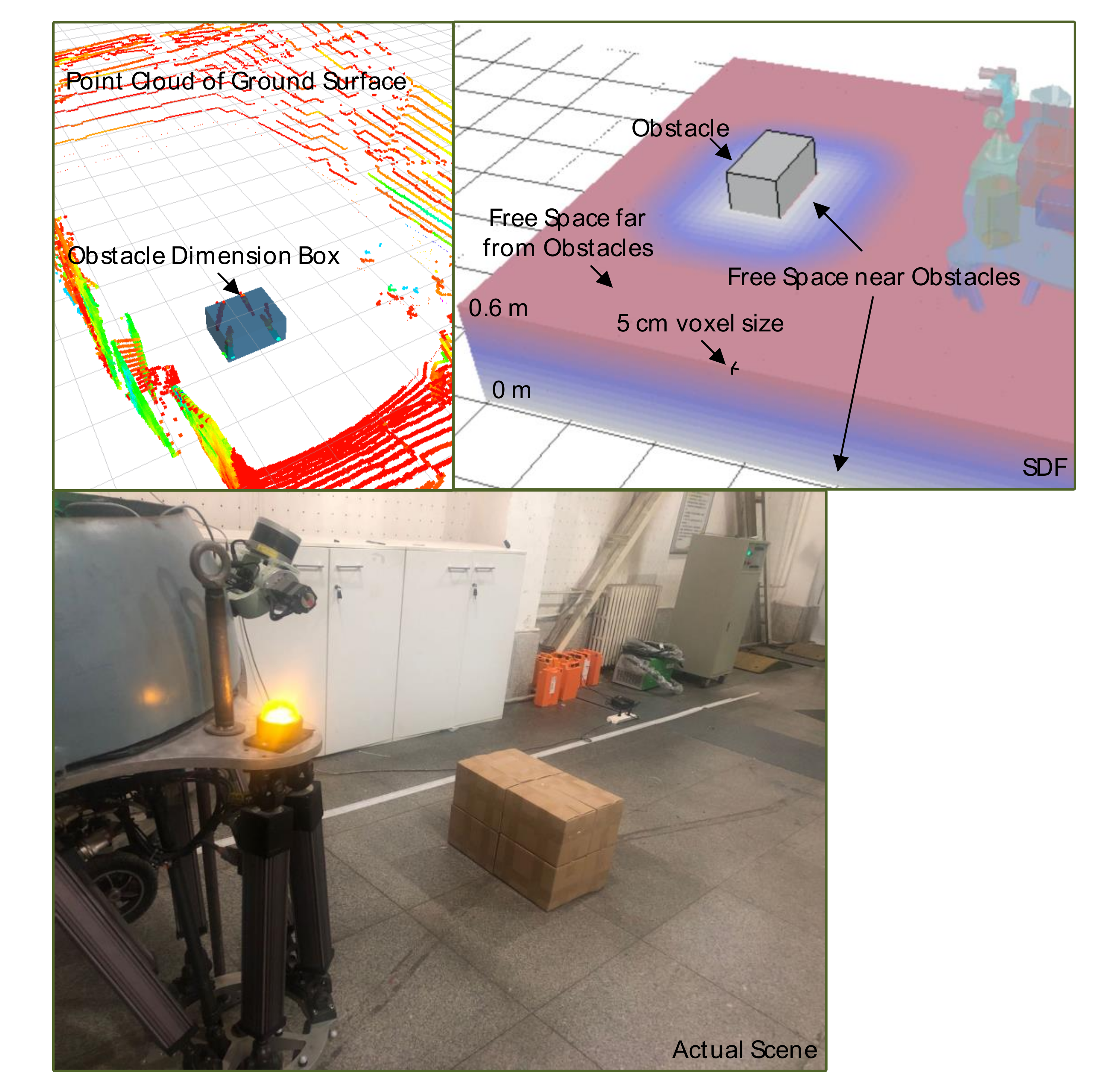
Calculate the signed distance filed from robot-centric obstacle dimension box, which is collect from lidar after filter the ground point cloud. The incremental linear fitting method and KD tree clustering approach were adopted to describe width and height of obstacle box.
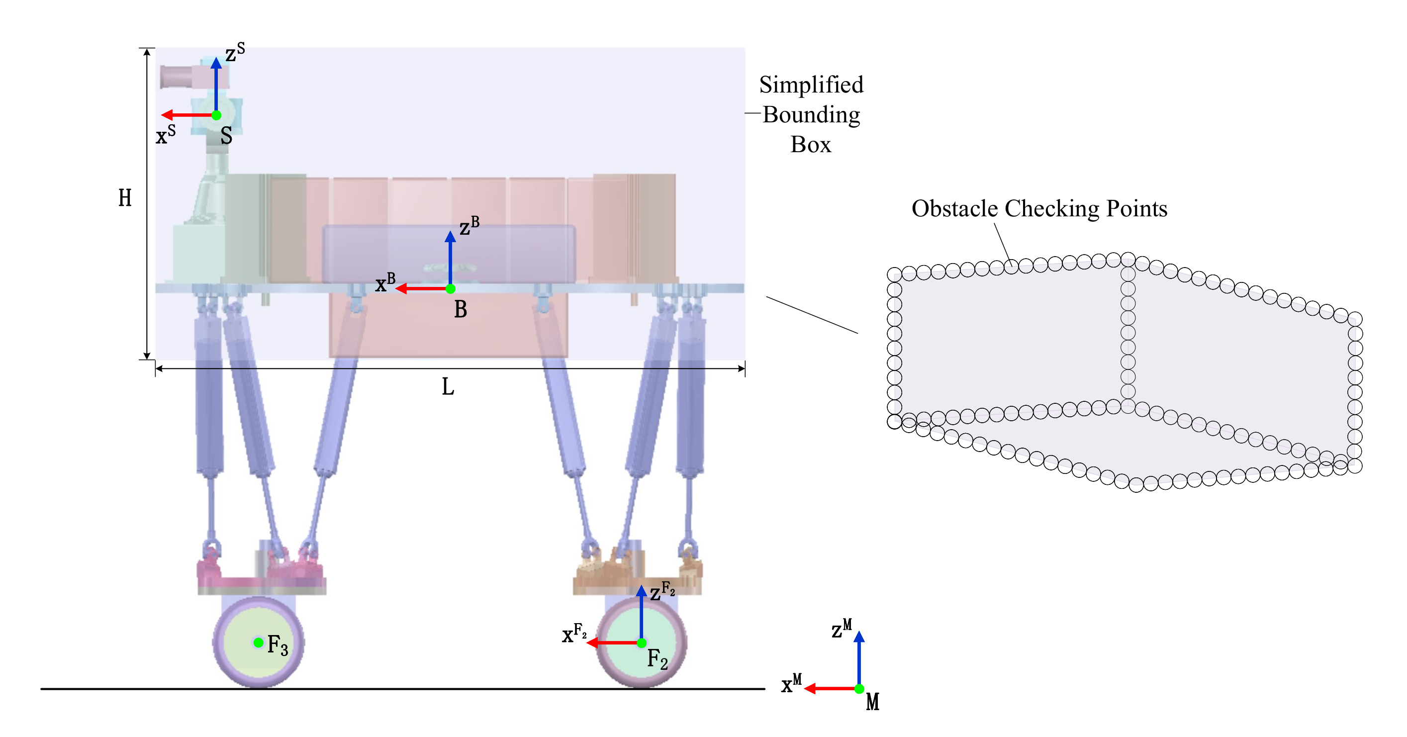
Introduce a deformable bounding box abstraction for WLHR model, which is incorporated with SDF representing obstacles to check collision.
Propose a covariant gradients-based trajectory optimization formulation that is applied to generate smooth and collision-free motions for a rigid deformable WLHR through changing trunk height and wheelbase. Integrate the planning framework into morphing locomotion in confined space, satisfying the kinematic reachability, smoothness, and obstacle avoidance constraints.
Validate feasibility of our methodology on a simulated model and practical WLHR prototype in four scenes. A suite of intensive analysis and comparison for algorithm computation and robot deformable properties are displayed through line chart and histogram.
2. A Wheel-Legged Robot (WLHR) Description and Framework Overview
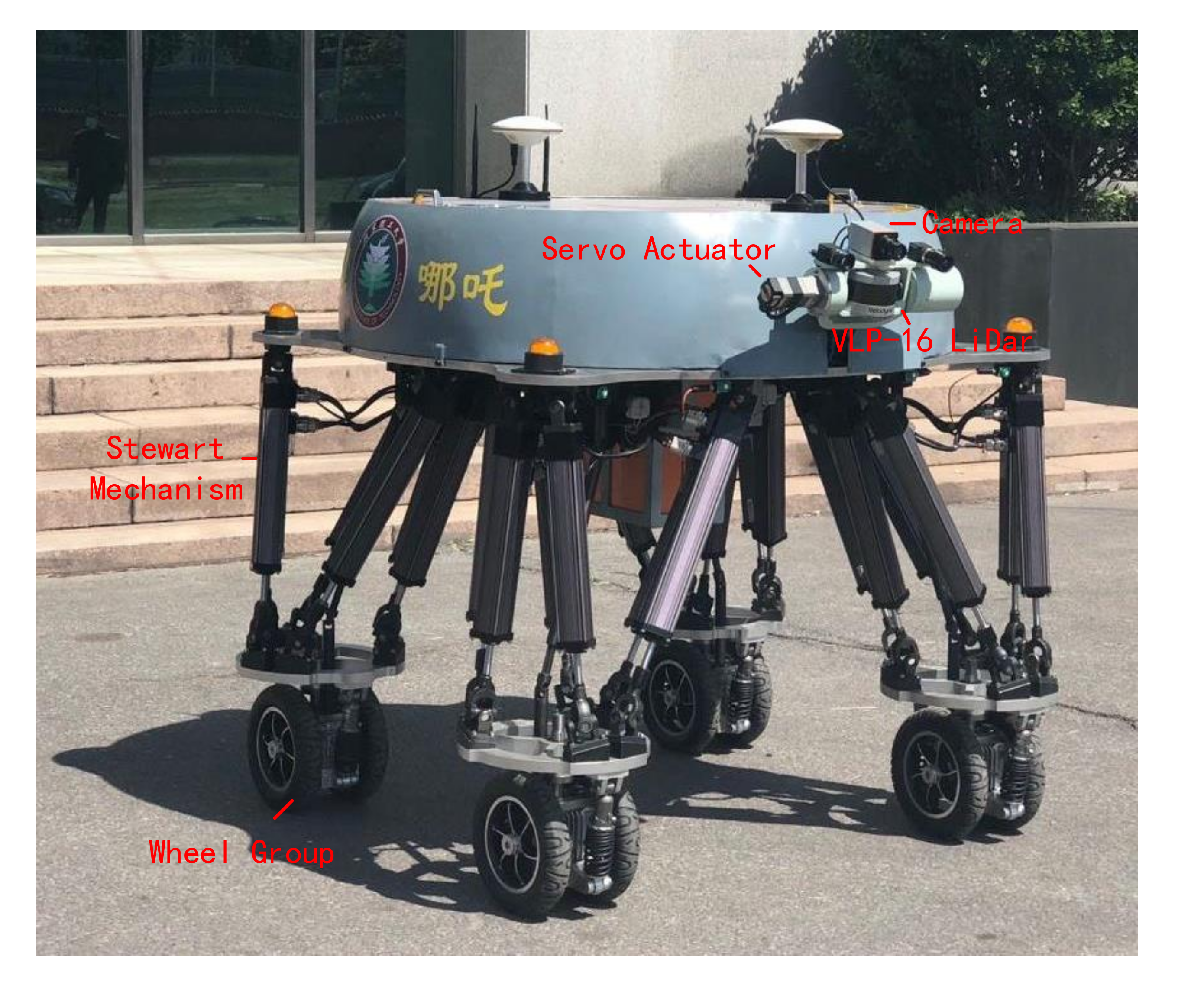
The BIT-NAZA robot showed in
Figure 1 is designed as a quadrupedal machine equipped with four active wheel groups at four pelmas respectively. The mechatronic structure of each leg is comprised of six stretchable linkages with electrical actuators in parallel. The parallel construction enhances the body’s payload capability and possesses six freedom of degrees, rendering the feasibility of horizontally rotating the wheel orientation. Furthermore, there are a linear displacement encoder and a force sensor internally-installed in each linkage scaling the displacement and force along stretching orientation. An inertial measurement unit (IMU) is mounted on robot torso to supply angle, angular velocity, and angular acceleration data along three axes. The robot stands approximately 1.4 m high when every linkage reaches its neutral position, as well as can maximally afford 350 kg with a total mass of about 300 kg (encompassing overall hardware, batteries and sensors).
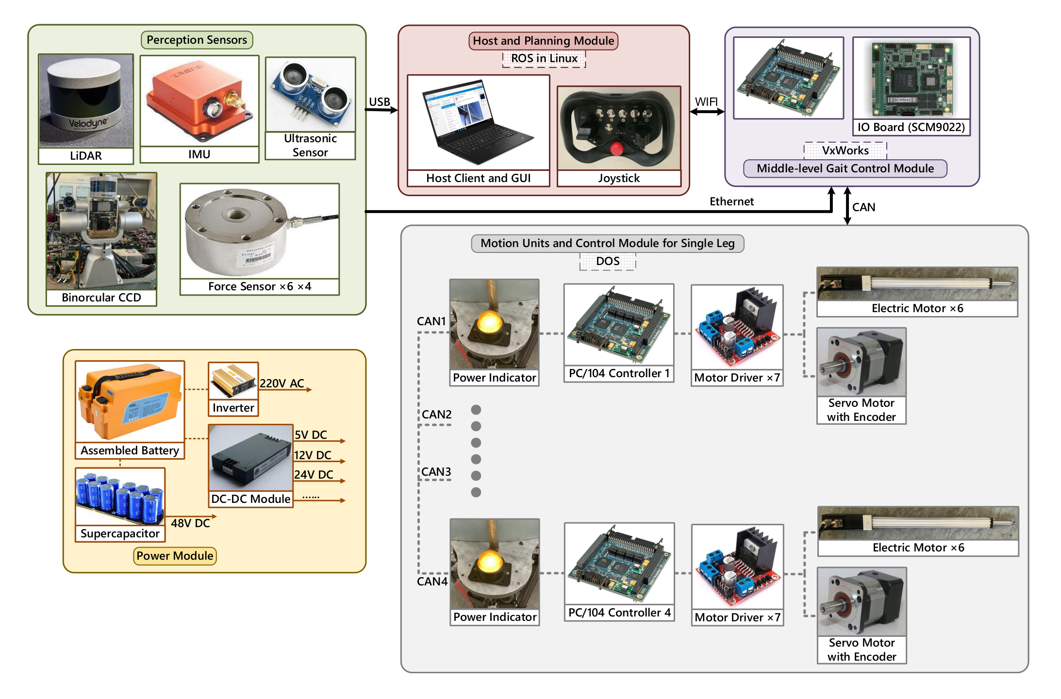
The BIT-NAZA was developed as a research platform for unmanned autonomous moving missions in challenging environments. Accounting for running on rugged terrains, the wheel-legged robot is capable of switching different types of locomotion among regular quadruped stepping, full-wheeled driving, and stepping-rolling hybrid locomotion, in which the Stewart mechanism urges wheels and robot base to change relative positions constituting a deformable robot independently. The proposed system architecture contains multiple hardware and software components embodied in
Figure 2. In addition to low-level actuator and middle-level gait control module operating in DOS and VxWorks separately, the mapping data disposing and planning module leverages the program environment of ROS in Linux where the scheduled framework engaged in.
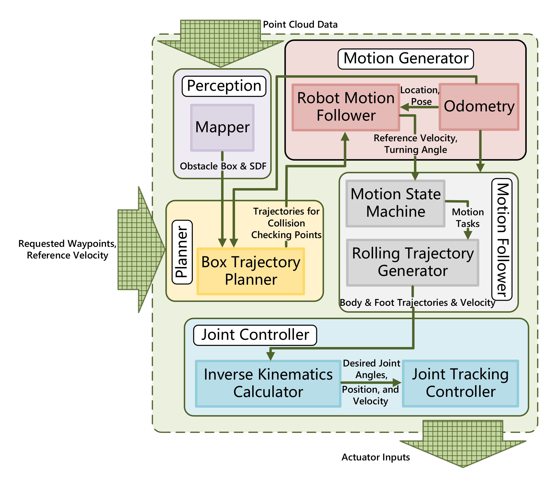
The block drawing scratched in
Figure 3 depicts the exploited planning architecture with the input of point cloud data (PCD) collected from lidar or other depth perceptive sensors and user commands including reference velocity and requested target waypoint. The ultimate task of
is to plan online a pertinent sequence of trajectories for collision checking points distributed on bounding box, which allows the robot to traverse convex obstacles or pass confined space pursuing assigned waypoints. The LiDar equipped on robot accumulates point cloud data, which is transformed into width, height, and length dimension of obstacle in
module. A deformable planning approach exploits covariant gradient method to prevent robot from obstacles through signed distance field, forming a smooth trajectory for bounding box abstraction. The optimal trajectories produced from
are transformed into subsequent motion states for body and wheels in terms of current robot configuration through robot kinematic definition in
. Additionally, wheeled odometry that accumulates the total turning angles of wheels in charge of the current location of robot and collects the trunk posture information from body-mounted IMU. The modular layer where
formulates reactive maneuver helps us to seamlessly connect the
and
. The corresponding commands for different motion units are transferred and converted into joint tracking controller to follow the planned Stewart-based kinematic solution. The final output from our planning framework is actuator input containing required joint displacement, velocity and acceleration for 24 electrical cylinders and wheel motors.
4. Obstacles Representation Collected from VLP-16 Lidar
As for the procedure of acquisition and evaluation of terrain information in this work, an on-board terrain data server enforces a Velodyne VLP-16 LiDAR sensor to collect PCD, quantitating terrain topology that is adjacent to robot. The field of view (FOV) of VLP-16 ranges 360 degrees horizontally and degrees vertically, whose available distance extends to 100 m. Additionally, the servo actuator mounted on turntable is responsible for sensor orientation adjustment to perceive farther region environment data.
After filter the ground point through multi-frame point cloud fusion and incremental linear fitting approach, the obstacle PCD is directly transformed into obstacle box information including corresponding dimension and distance from robot in map frame [
35]. The topology relationship between discrete PCD is constructed by KD-Tree method. The Pairwise Linkage manages the obstacle cluster. Set a global distance
to distinguish neighborhood set and other PCD sets. For each point
, record corresponding nearest distance in sequence
. Calculate cut-off distance
with customized weight
and mid-value in
:
The point density is calculated through recent point number and Gaussian kernel function as follows:
in which
represents distance between point
and
inside epsilon neighborhood
.
is the nearest point whose corresponding density of is larger than that of
and mark that they are in a same cluster. If the density of
is a local maximum, we consider
as center of cluster. Project all of obstacle points on X-O-Y ground surface and X-O-Z surface model, we can compute precise width and height dimension of obstacle.
The metric which evaluates the distance from collision checking element to the boundary of nearest obstacle enables the function to be pre-calculated and stored that employs Euclidean Transform Norm. A straightforward strategy is implemented to estimate obstacle potential in static exploring space. The SDF calculation is constructed as a pre-processing procedure before optimization to realize collision checking.
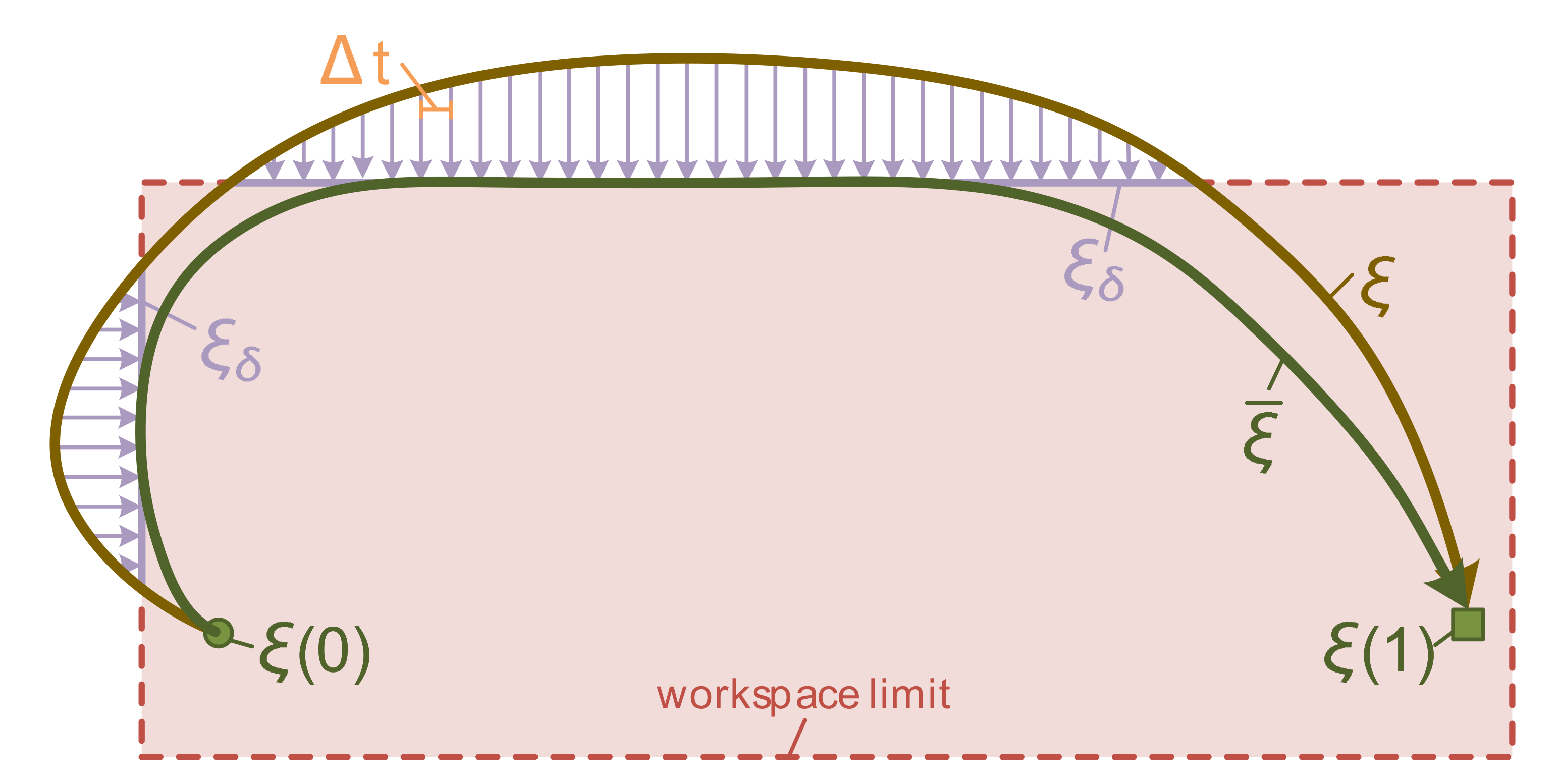
A workspace cost function
is to penalize the robot configuration
in the workspace for serving collision checking elements
to approach obstacles.
Furthermore, we adopt the finite differencing to approximate the obstacle distance gradient , boosting the collision checking speed utilizing the primitives on geometric abstraction.
Subsequently, the SDF computation is updated with resolution in our case of 5 cm per pixel through Equaption (
7), whose disposing course is displayed in
Figure 5. The top figures visualized PCD collection from Velodyne VLP-16, obstacle box visualization and SDF representation that describe the environment information. A robot-centric 4 m × 3 m × 0.6 m SDF layouts cell by cell with different color following the obstacle cost function
variation.
6. Results and Discussions
This section represents and discusses the simulation and experiment results based on the entire planning framework shown in
Figure 3. Simulations are applied on a simulated BIT-NAZA robot model in Virtual Robot Experimentation Platform (V-REP) furnishing with VORTEX dynamic engine. The BIT-NAZA robot described in
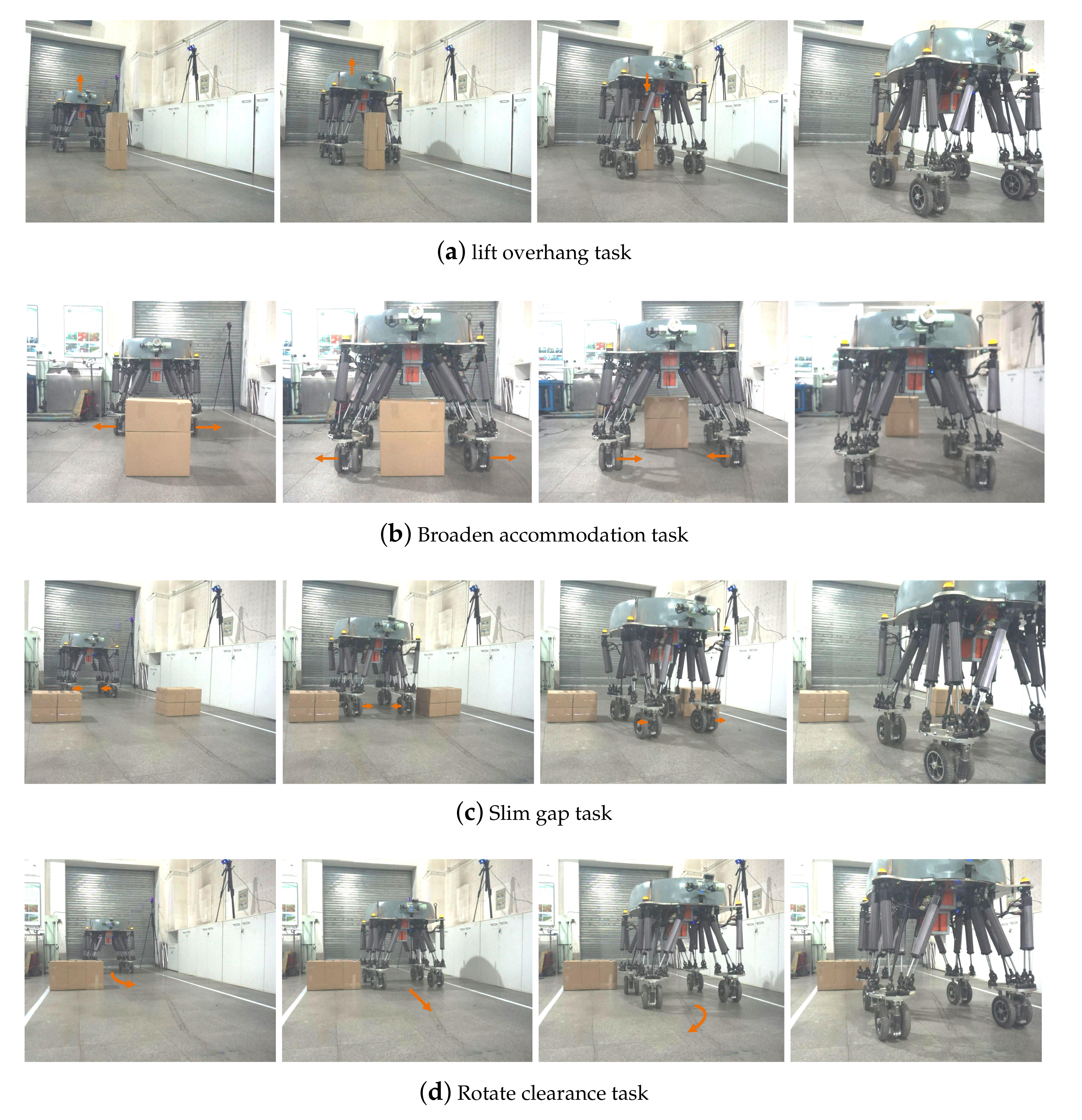
Section 2 is used for the experiment verification. Our ultimate prospect is to plan a set of trajectories for COM and deformable footholds polygon from the current configuration to a requested waypoint and traverse the obstacles in various challenging exercises. Four sorts of essential implements endeavor to examine whether the motion generated from the proposed framework is feasible, containing broaden accommodation, lift overhang, rotating clearance, slim gap assignments. All of the planning trajectories were created on the basis of SDF representation of obstacle produced by PCD and obstacle box dimension. We underline that each motion appeared deformably credits to assigned waypoints, user-input velocity, and situational requirement. It also showcased that further guidance in the form of how our method can solve analogical issues with remarkably better terrain-adaptive performance and computational efficiency assessment.
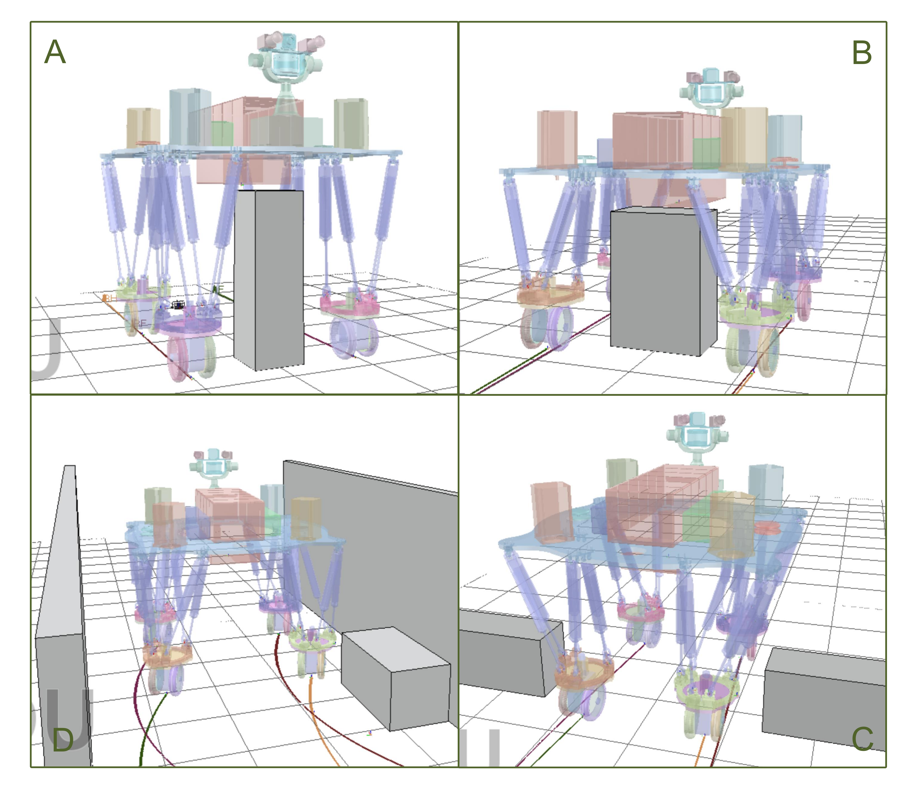
Progressively,
Figure 7 depicts the produced motion that deformably performs the negotiating capability in four diverse assignments. Each task starts from the neutral configuration when all of the electronic cylinders extend to half of their maximum length as a preparation to willingly shrink and expand. For lift overhang, the robot has to lift its trunk, which results in a corresponding increment in width. We achieved this performance through coupling iterating update Equation (
8) with bounding box abstraction through Jacobian
, which was notably mapped to the changes over Z-position
z that grows. Briefly, the selecting treatment of initial trajectory
was stochastic and even already collides with some obstacles.
and stored SDF prevent bounding box from obstacles and then proceed with numerical optimization. Broaden accommodation event enables the robot to broaden its span and increase the width of bounding box, as evidenced by the linear implementation of
. Slim gap function allows the robot to shrink the width of the bounding box around the body, which is equivalent to that of foothold polygon and passes over the narrow lane, also motivating the differential application of
. Rotate clearance behavior is an extraordinarily non-deformable action that requires the robot to orient its wheels and detour obstacle in a narrow passage. The configurational parameter edits, the steering angle of wheels
, are regulated by synergistic trajectory command in gradient descent update. We note that to obtain these motions, it is necessary to define an input moving velocity 0.1 m/s for active wheels from user manual law. To diminish the frictional error from contacting wheels with the ground and possible slippage error from high dynamic wheeled turnings, mastering adequately low wheeled speed features of great concern.
6.1. Simulations
The simulation experiments can help us to analyze and compare the result of the proposed algorithm and robot configuration variation, which is evaluated in 10 trials for each circumstance and obstacle event. In the first
case (
Figure 7A), we progressively change the height of obstacle with increments of 5 cm additional passable height while rolling with neutral configuration. Each time it enables robot to lift accommodate space to pass through obstacle. We found robot could pass over 90 cm obstacle with 100% success rate and the supreme 105 cm with 40%.
During the
event (
Figure 7B) in simulation, broadening wheelbase to accommodate wider obstacle rather than bypassing is a better approach to enhance motion efficiency. We examined this case on obstacles with different width and found that robot can pass a 62 cm width box with 100% success and 70 cm with 70% success separately in 10 trials.
Subsequently in the third simulation (
Figure 7C), we gradually shrink the gap breadth with reduction of 10 cm to test robot. It is demonstrated that robot could get through a 1.2 m gap with 100% success, 1.1 m with 80%, and 1 m with 30%.
The
rotate clearance in (
Figure 7D) steers robot to change wheel orientation without altering configuration, avoiding obstacle. How much the the maximum turn angle is relies on distance between obstacle and robot. We fixed obstacle on a spot 1 m far from robot and changed different goal to evaluate the turning angle that is 90
with 100% success.
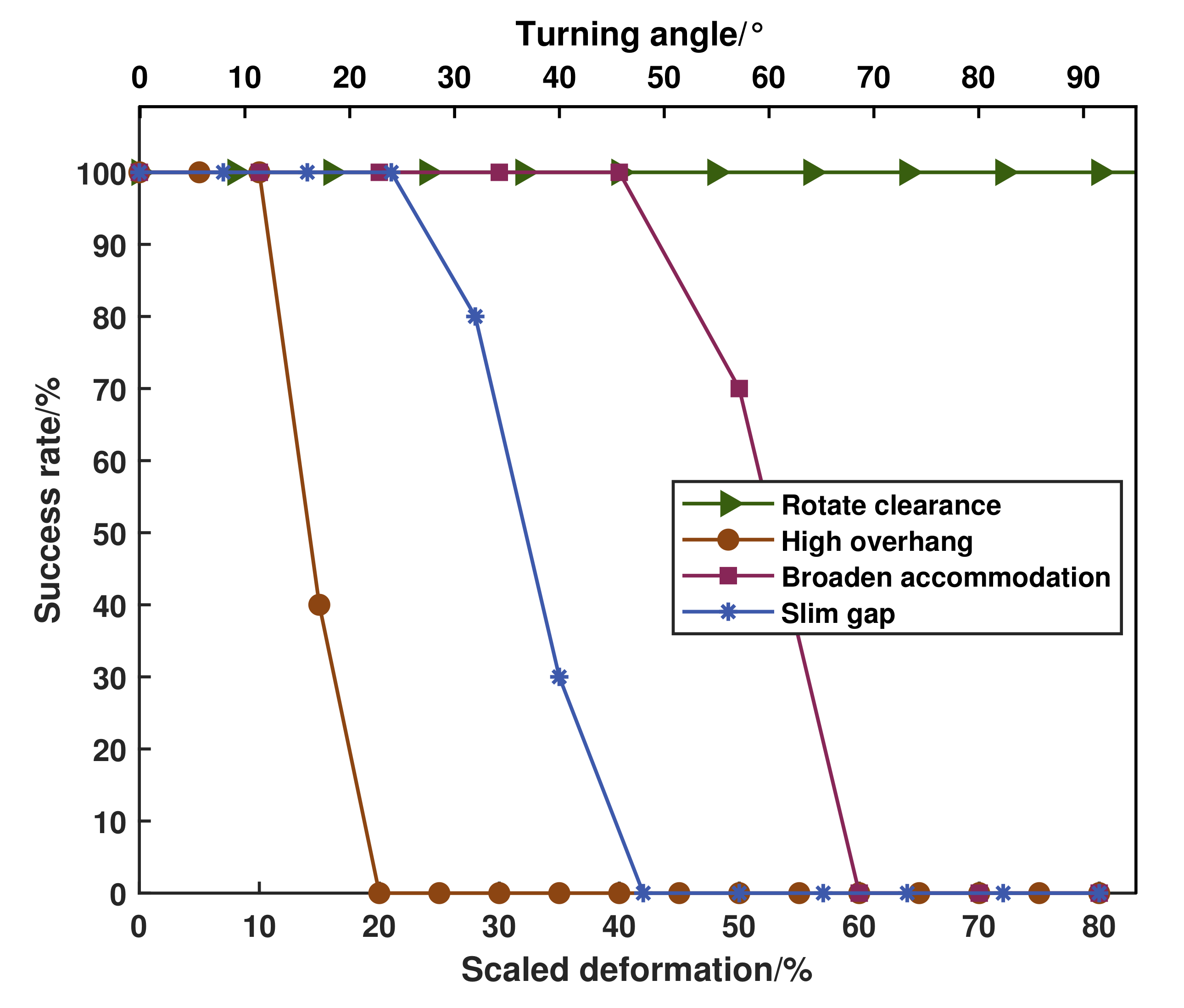
Although the success rate shown in
Figure 8 described the performance of our planning approach, the results may change when we select different parameters. There are many user-defined parameters in the optimization process, such as the learning rate ∇ and the default obstacle threshold
. Larger learning rate can obtain larger trajectory update velocity, boosting sampling interval for next trajectory. But it could miss the local minima point, resulting in a smaller objective function point. Enlarging default obstacle threshold can increase obstacle avoidance ability that prevents trajectory farther from obstacle, but exploring an optimal trajectory in extremely confined space becomes difficult. In our method, the user-defined parameters tuning method generally is based on our experiences or prior knowledge. For example, when optimization fails, we will try to reduce the learning rate. In our future work, we will attempt to apply learning-based methods to select and optimize those parameters intelligently.
6.2. Performance Evaluation
For the purpose of graphically visualizing the comparison for deformable adaptation percentage among four mentioned assignments, and we analyze it in simulated cases for security. Furthermore, we examined the success rate of the proposed planner and recognized that it is precisely the absence of diverse environment restriction influences the success rate. 10 simulated examinations were governed for each specific event and condition, whose results are depicted in
Figure 8. Only the examining condition for
rotate clearance case is rotating angle, while the ones for the other three are scaled deformation percentage defined in
Section 6.1, which equals to the maximum deformable measurement as a percentage of original volume. Obviously, the maximum steerable angle
evaluated by Stewart kinematics, the success rate for all of rotatable angle in testing
rotate clearance task reached 100%. Commonly, the success rate of deformable planning algorithm reaches
when conditional constraints of target terrain templates satisfied our model abstraction limits, and its variation tendency matches and are smaller than the deformable scale we calculated through kinematic analysis in accordance with Reference [
33]. For instance in
lift overhang, the robot body can be lifted maximum 15 cm that equals to 15% of robot’s neutral height, but the success rate of corresponding environment for robot to attain this configuration is only 40%.
6.3. Experiments
In addition to experiments, we implemented the entire pipeline from
Figure 3 on the BIT-NAZA WLHR such that they demonstrate the deformable capability. Likewise, all of the obstacle-negotiation tasks in a confined space were also performed in realistic situations, as disclosed in
Figure 9. The robot detected obstacle locations
in sensor frame and transformed it together with robot configuration on uniform map frame
, which is defined though the projection of initial COM position and foot contacting surface. The robot posture can be measured by IMU and height can be computed through basic mechanism size and Stewart forward kinematics through extending amount of electrical cylinders. In each experiment, we generated a SDF description around robot with 6 m × 4 m × 3 m dimension scanned from Velodyne-16 LIDAR, which has been elaborated in
Section 4. To record the final trajectories generated with four wheels and COG of the robot, we take advantage of displacement sensors embedded in each electrical cylinder. They allow Newton-Raphson iteration of forward kinematics to calculate lateral, altitude trajectories and rotation angles of four Stewart mechanism. The wheeled odometry accumulates and averages the traveled distance of whole robot, that is COM. Apart from the environment perception sensor that VLP-16 LIDAR, we employed an additional camera jointly installed on the controllable holder, identifying the white color line on the ground. Especially in
rotate clearance assignment, stamping white lines adhered to the ground as 1.6 m-high walls which generates a cluster of corresponding SDF, as a result of avoiding superfluous scene construction. Due to the field size constraint, we only can test each task for one way planning and all of goals are about 3 m far away from COM.
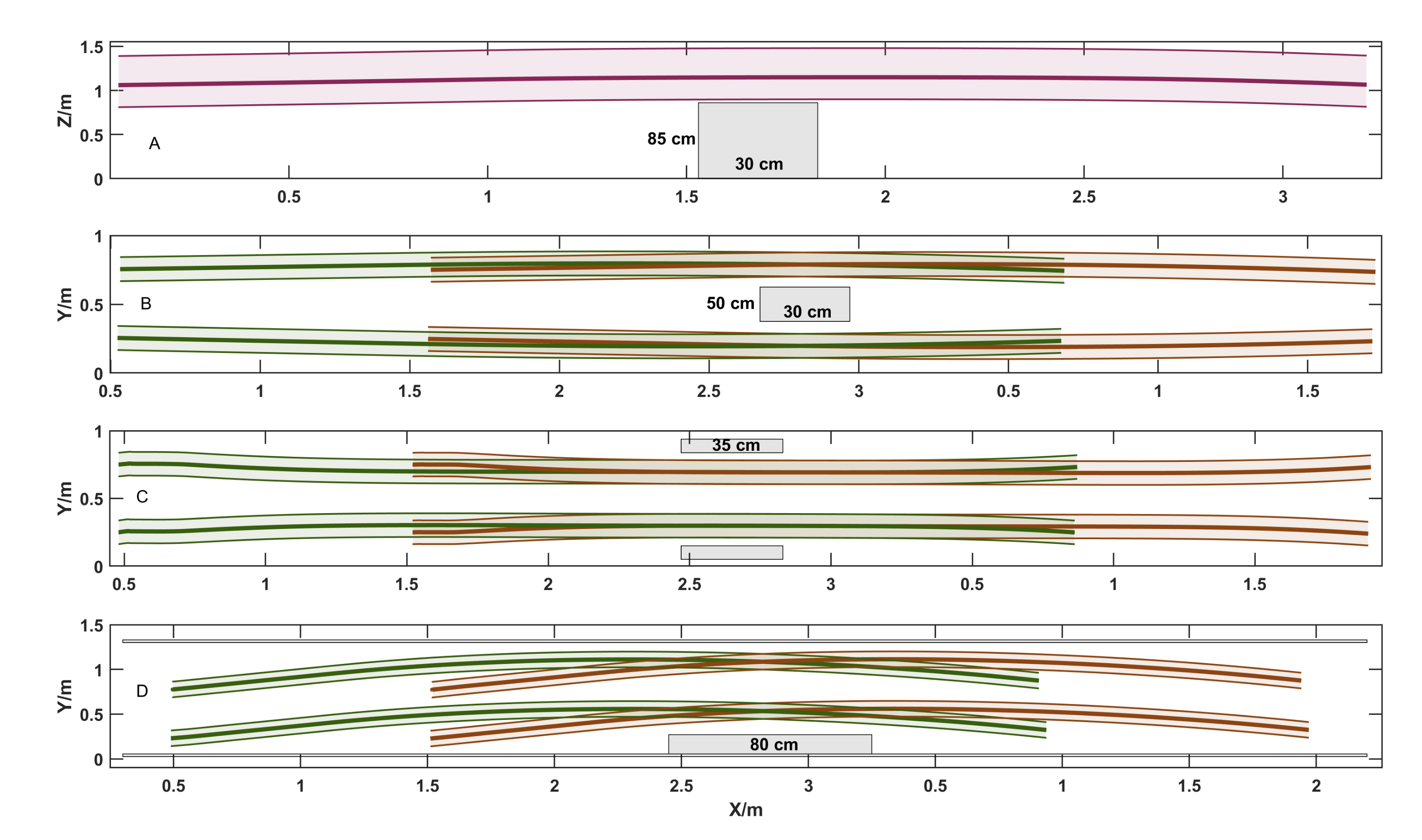
Note that we utilized the RGB color convention to draw diverse action units and their relationship with obstacles in
Figure 10, demonstrating the executive smooth trajectories. The thick brown and green line fractions represent front and hind wheeled trajectories separately, whose corresponding thin lines and enclosed shadow area indicate their dimensional boundary of wheels. The thick strawberry line describes the COM trajectory, how the truck border moves were also portrayed in the same color. Besides, the gray shadow boxes present obstacles in various sizes and scenes. It is sufficiently apparent that robot could negotiate different obstacles and reach the user-specified target waypoints, while deformable iterations optimized the entire motion generation in four experimental cases.
While conducting the first case (
Figure 9a), robot encountered an obstacle which had increments of 9 cm additional passable height while rolling with neutral configuration, that was a totally 1 m high box. The goal of the
lift overhang task is to enable the robot to explore the clearing space upwards, finally recovering to its initial arrangement.
Over the
task (
Figure 9b), the robot spanned about 7 cm and 12 cm towards left and right side independently for the obstacle 2.4 m far away. The left and right wheels turn towards outside to enlarge the support polygon which assists robot with the deformable task of accommodating relatively wider obstacle beneath its trunk.
Whereas (
Figure 9c) constructed by two obstacles with close distance, the execution of
slim gap routine demonstrated the adaptive capability to a narrow passing space which possessed the width of 1.3 m. The foothold support polygon shrinked about 12 cm and 9 cm towards left and right respectively. As the width of the bounding box determines the lateral shrinkage, the lateral displacements for front and hind wheels which are on the same side are the same.
The final case (
Figure 9d) performed the
rotate clearance conduction without a morphological configuration of wheelbase. As expected, the proposed planner instructs robot to rotate and get round the right box, steaming into free space on the left side. The left and right walls are too high to cross, so it is impotent to conduct
lift overhang behavior and reasonably mastery the robot in a confined space. The dimension of the obstacle are length of 0.8 m and width of 0.43 m.
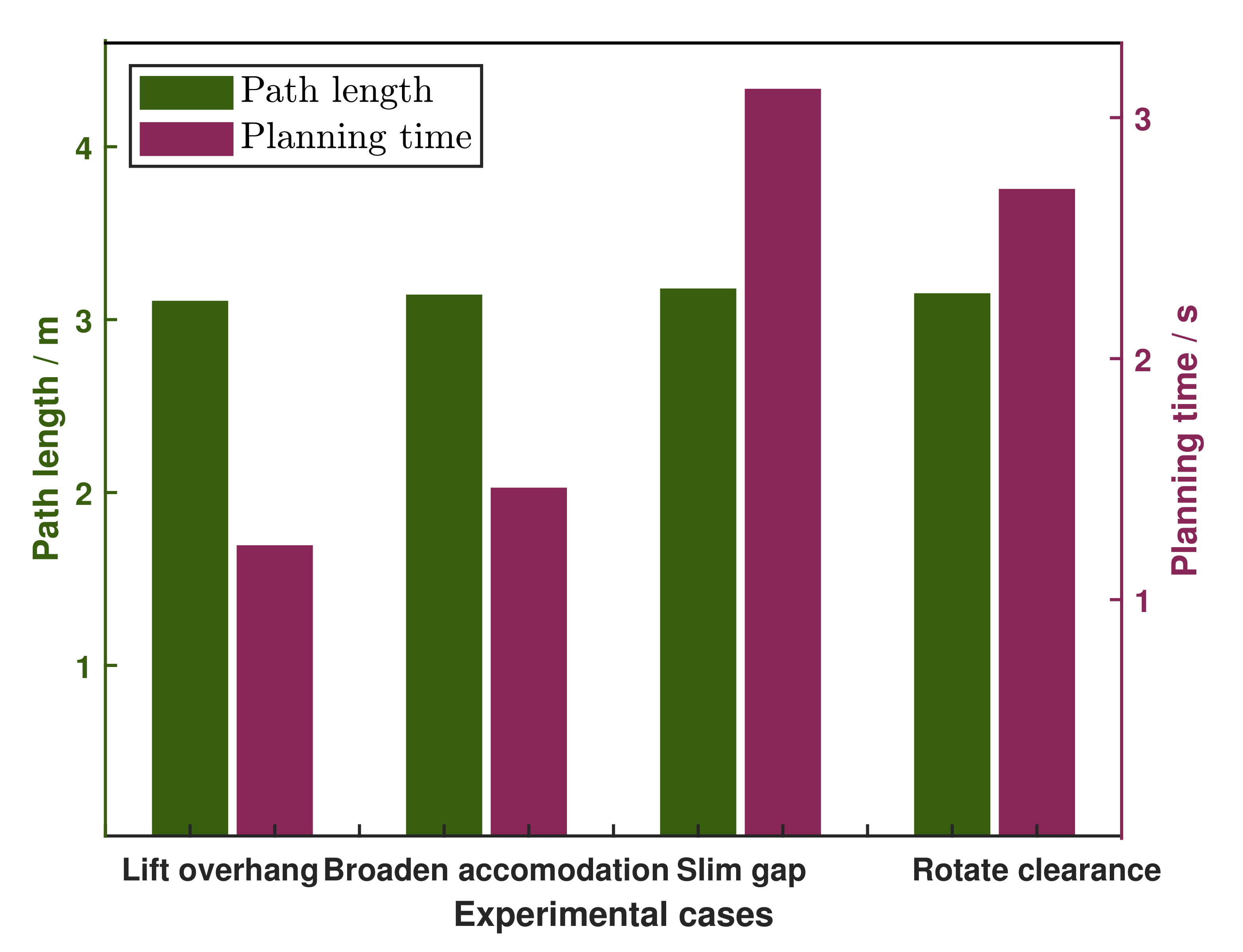
Besides, we examine and compare the numerical traits of path length and planning time for four diverse simulated trials, whose results are illustrated in
Figure 11. In general, we choose a goal which is about 3 m far from current robot configuration and explore the target trajectory. Although the path lengths for four trials were almost the same, the planning time displayed irregularly in which the one for
slim gap event was the supreme example. The quantity and intensity of obstacles, as well as unoccupied space in narrow environment directly influence the collision checking efficiency and planning time.
Moreover, it can be carefully scrutinized that after traversed obstacle, the planner had been continuing to gradually lift the robot to extend the trajectory, which picked lift overhang behavior as an instance. The appearance of this phenomenon denotes that covariant gradients optimization undertakes searching trajectory with the lowest objective functional metric where obstacles end up inside current examined coverage between collision checking points. This developed into a trade-off among weighted parts and , since simply adjusting higher than could cause a more significant possibility of collisions.


