Microstructure-Based Fiber-To-Chip Coupling of Polymer Planar Bragg Gratings for Harsh Environment Applications


Abstract
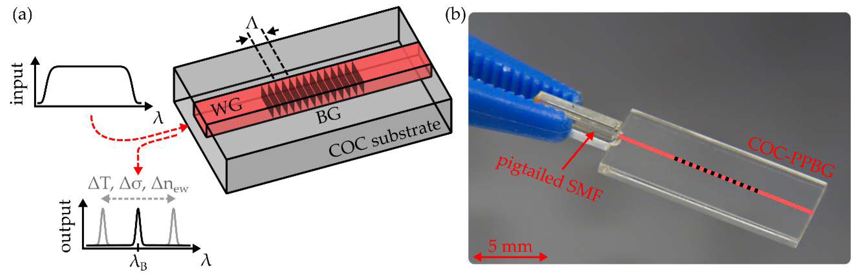
1. Introduction
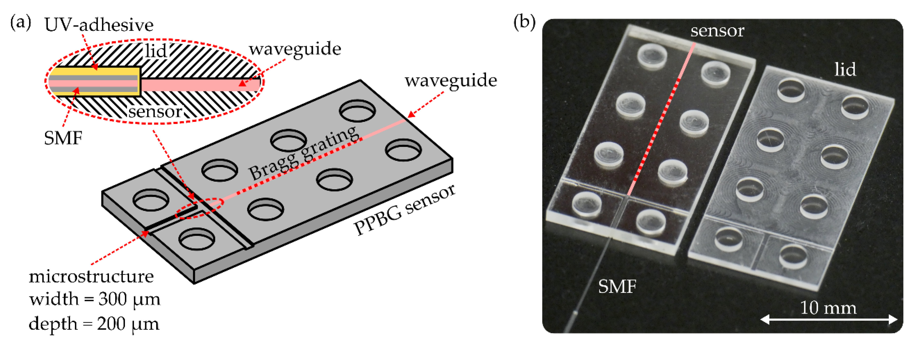
2. Device Fabrication
3. Results and Discussion
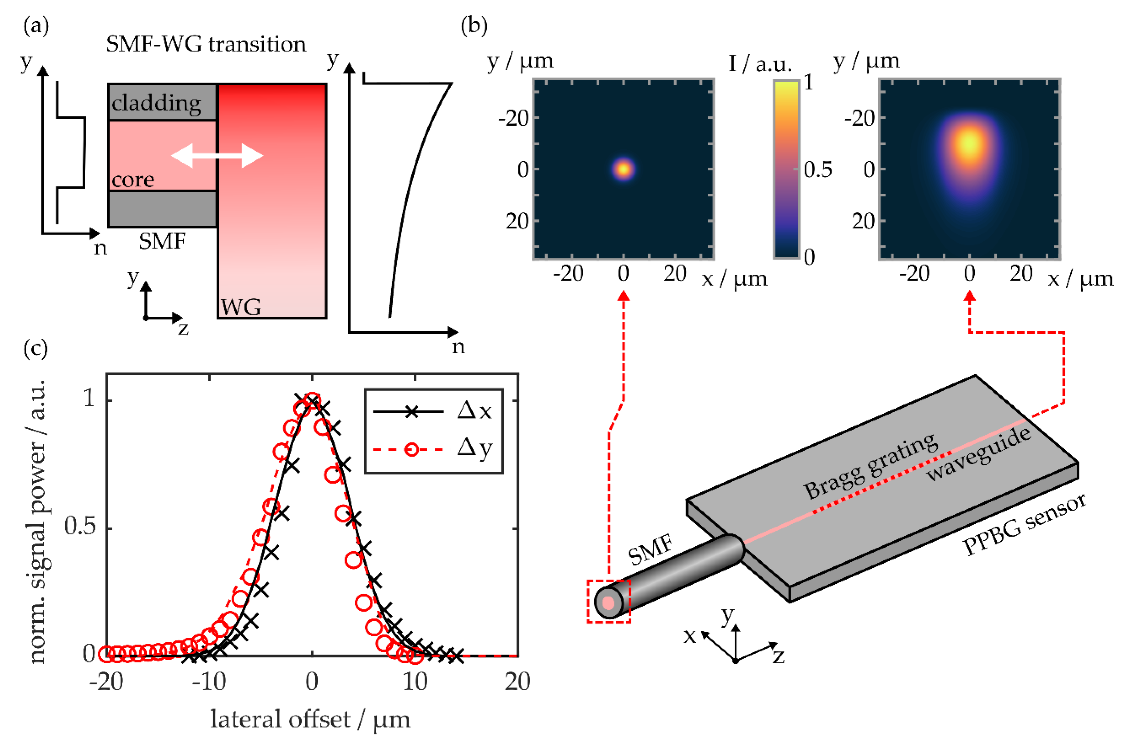
3.1. Lateral Misalignment
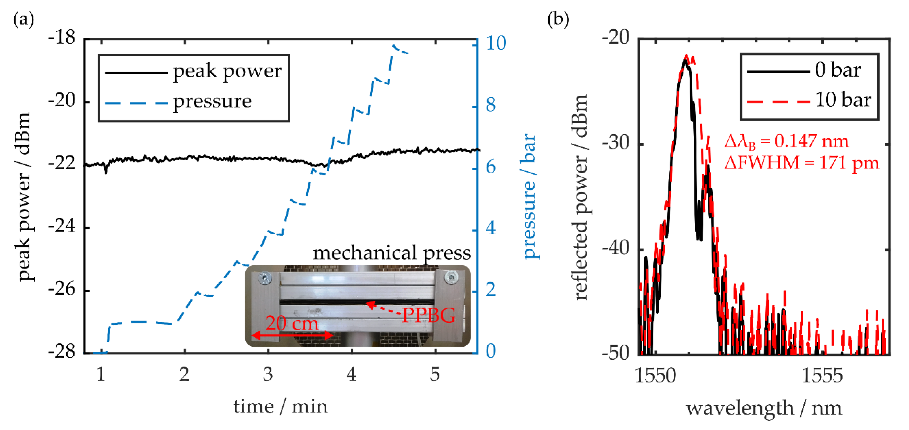
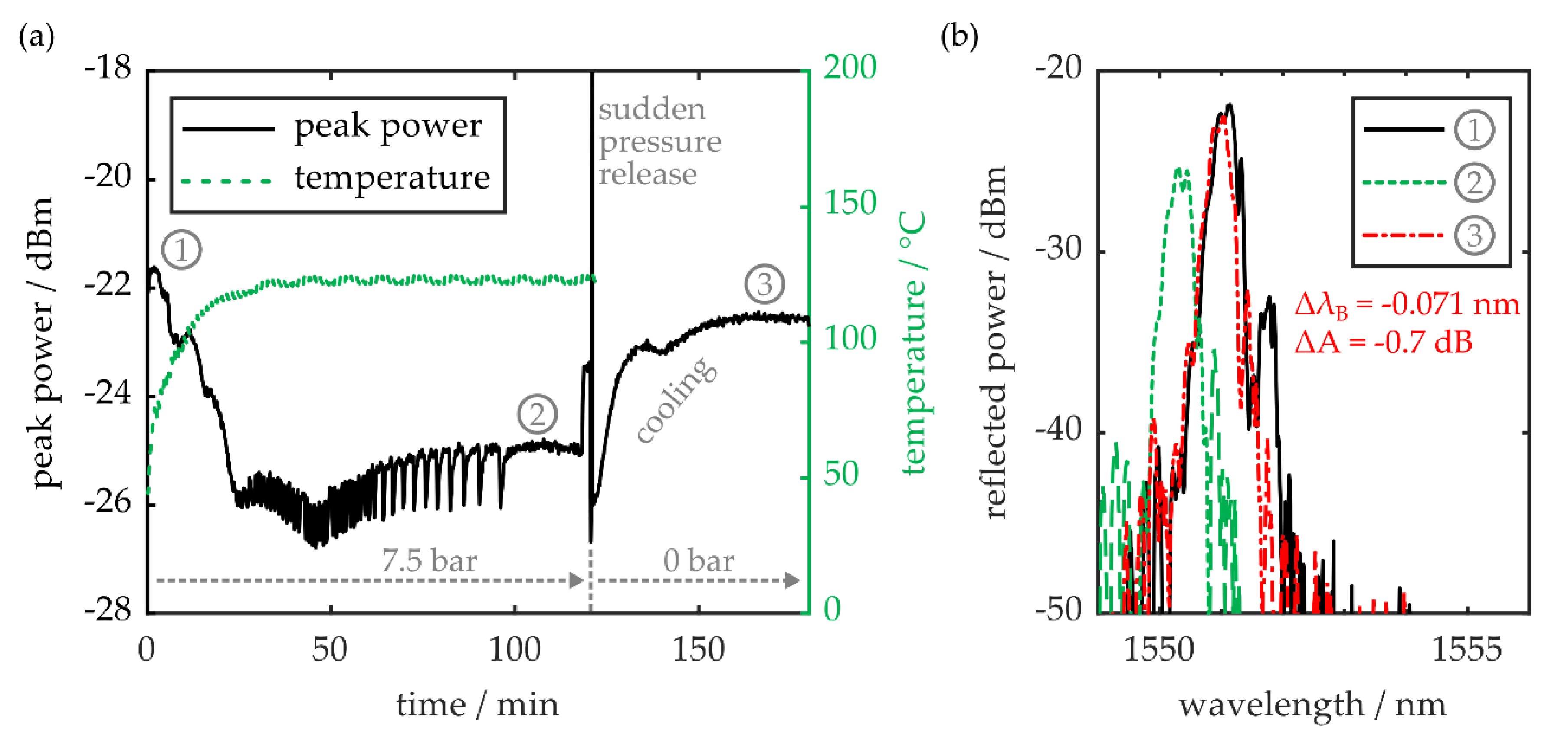
3.2. Pressure and Temperature Resistance
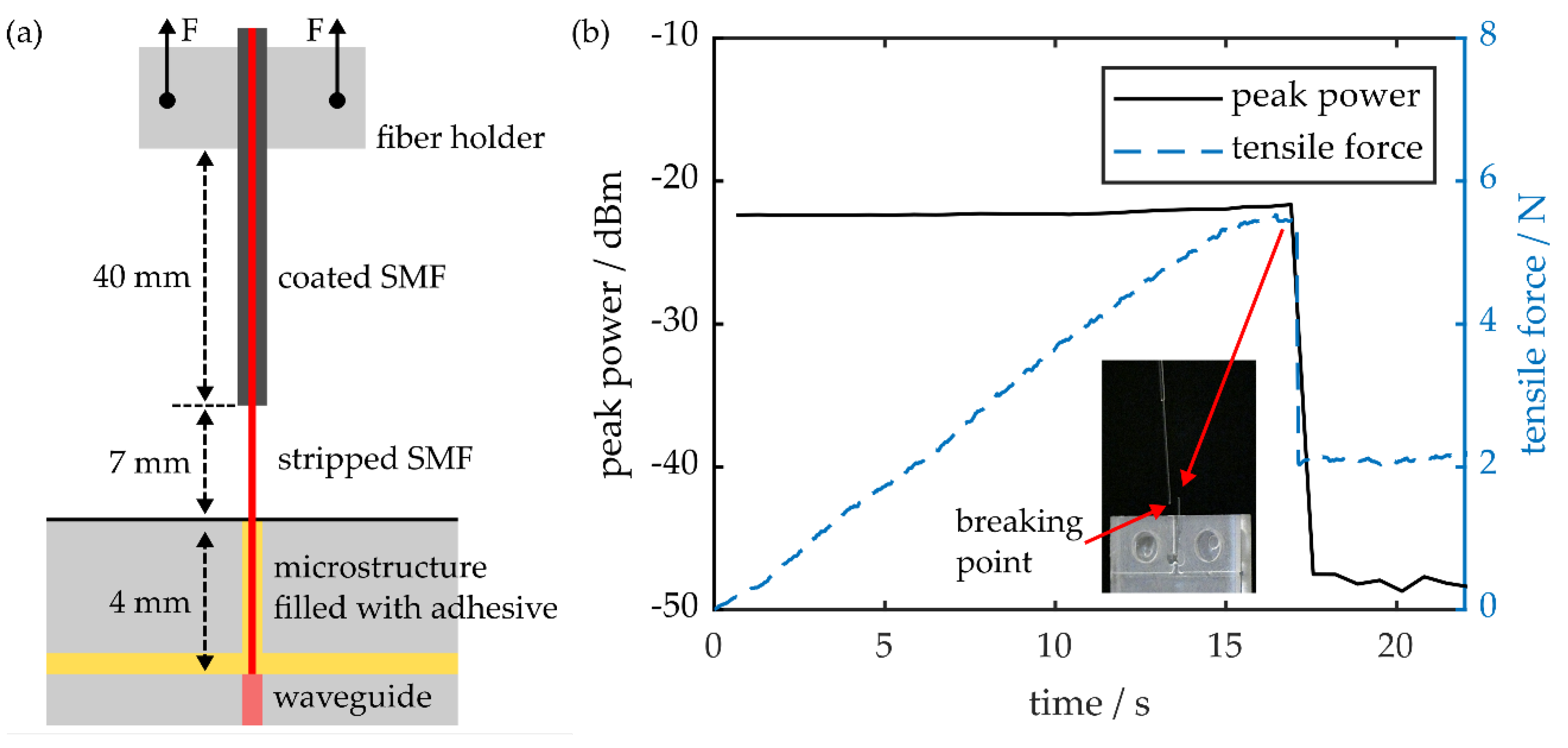
3.3. Resistance to Tensile Forces
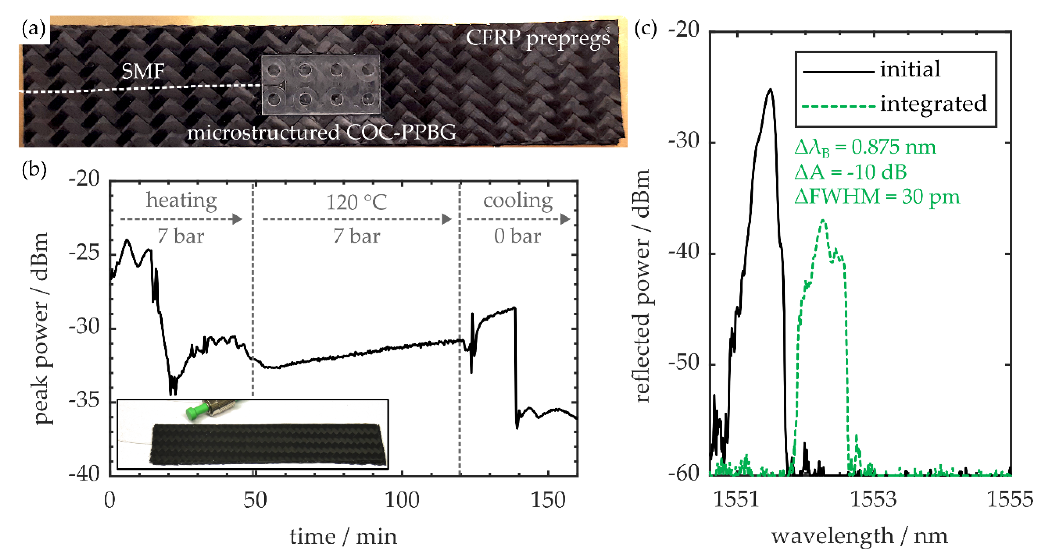
3.4. Carbon Fiber Reinforced Polymer Integration
4. Conclusions
Author Contributions
Funding
Acknowledgments
Conflicts of Interest
References
- Krohn, D.A.; MacDougall, T.; Mendez, A. Fiber Optic Sensors: Fundamentals and Applications, 4th ed.; SPIE Press: Bellingham, WA, USA, 2014; ISBN 9781628411805. [Google Scholar]
- Allwood, G.; Wild, G.; Hinckley, S. Fiber Bragg grating sensors for mainstream industrial processes. Electronics 2017, 6, 92. [Google Scholar] [CrossRef]
- Lopez-Higuera, J.M.; Rodriguez Cobo, L.; Quintela Incera, A.; Cobo, A. Fiber optic sensors in structural health monitoring. J. Lightwave Technol. 2011, 29, 587–608. [Google Scholar] [CrossRef]
- Qiao, X.; Shao, Z.; Bao, W.; Rong, Q. Fiber Bragg grating sensors for the oil industry. Sensors 2017, 17, 429. [Google Scholar] [CrossRef] [PubMed]
- Liu, Z.; Tam, H.-Y. Industrial and medical applications of fiber Bragg gratings. Chin. Opt. Lett. 2016, 14, 120007–120011. [Google Scholar] [CrossRef]
- Webb, D.J. Fibre Bragg grating sensors in polymer optical fibres. Meas. Sci. Technol. 2015, 26, 92004. [Google Scholar] [CrossRef]
- Broadway, C.; Min, R.; Leal-Junior, A.G.; Marques, C.; Caucheteur, C. Toward commercial polymer fiber Bragg grating sensors: Review and applications. J. Lightwave Technol. 2019, 37, 2605–2615. [Google Scholar] [CrossRef]
- Rosenberger, M.; Eisenbeil, W.; Schmauss, B.; Hellmann, R. Simultaneous 2D strain sensing using polymer planar Bragg gratings. Sensors 2015, 15, 4264–4272. [Google Scholar] [CrossRef]
- Rosenberger, M.; Pauer, H.; Girschikofsky, M.; Woern, H.; Schmauss, B.; Hellmann, R. Flexible polymer shape sensor based on planar waveguide Bragg gratings. IEEE Photonics Technol. Lett. 2016, 28, 1898–1901. [Google Scholar] [CrossRef]
- Wochnowski, C. UV-laser-based fabrication of a planar, polymeric Bragg-structure. Opt. Laser Technol. 2009, 41, 734–740. [Google Scholar] [CrossRef]
- Rosenberger, M.; Hessler, S.; Belle, S.; Schmauss, B.; Hellmann, R. Multi-axial strain sensing using polymer planar Bragg gratings. In Advanced Photonics. Bragg Gratings, Photosensitivity, and Poling in Glass Waveguides, Barcelona; OSA: Washington, DC, USA, 2014; p. BM3D.2. [Google Scholar] [CrossRef]
- Rosenberger, M.; Schmauss, B.; Hellmann, R. UV-writing of a superstructure waveguide Bragg grating in a planar polymer substrate. Sensors 2017, 17, 1964. [Google Scholar] [CrossRef]
- Girschikofsky, M.; Rosenberger, M.; Förthner, M.; Rommel, M.; Frey, L.; Hellmann, R. Waveguide Bragg gratings in Ormocer®s for temperature sensing. Sensors 2017, 17, 2459. [Google Scholar] [CrossRef]
- Foerthner, M.; Rumler, M.; Stumpf, F.; Fader, R.; Rommel, M.; Frey, L.; Girschikofsky, M.; Belle, S.; Hellmann, R.; Klein, J.J. Hybrid polymers processed by substrate conformal imprint lithography for the fabrication of planar Bragg gratings. Appl. Phys. A 2016, 122, 213. [Google Scholar] [CrossRef]
- Missinne, J.; Teigell Benéitez, N.; Mattelin, M.-A.; Lamberti, A.; Luyckx, G.; van Paepegem, W.; van Steenberge, G. Bragg-grating-based photonic strain and temperature sensor foils realized using imprinting and operating at very near infrared wavelengths. Sensors 2018, 18, 2717. [Google Scholar] [CrossRef]
- Missinne, J.; Teigell Benéitez, N.; Chiesura, G.; Luyckx, G.; Degrieck, J.; van Steenberge, G. Flexible thin polymer waveguide Bragg grating sensor foils for strain sensing. In Proceedings of the Organic Photonic Materials and Devices XIX. SPIE OPTO, San Francisco, CA, USA, 28 January 2017; Tabor, C.E., Kajzar, F., Kaino, T., Koike, Y., Eds.; SPIE: Bellingham, WA, USA, 2017; p. 101010X. [Google Scholar] [CrossRef]
- Hessler, S.; Schmauss, B.; Hellmann, R. Temperature corrected lab-on-a-chip-platform with integrated epoxy polymer Bragg gratings. In Proceedings of the Optical Sensing and Detection V. Optical Sensing and Detection, Strasbourg, France, 22–26 April 2018; Berghmans, F., Mignani, A.G., Eds.; SPIE: Bellingham, WA, USA, 2018; p. 106800Q. [Google Scholar] [CrossRef]
- Hessler, S.; Rüth, M.; Sauvant, C.; Lemke, H.-D.; Schmauss, B.; Hellmann, R. Hemocompatibility of EpoCore/EpoClad photoresists on COC substrate for optofluidic integrated Bragg sensors. Sens. Actuators B Chem. 2017, 239, 916–922. [Google Scholar] [CrossRef]
- Hessler, S.; Bott, P.; Kefer, S.; Schmauss, B.; Hellmann, R. Multipurpose polymer Bragg grating-based optomechanical sensor pad. Sensors 2019, 19, 4101. [Google Scholar] [CrossRef]
- Rosenberger, M.; Hessler, S.; Belle, S.; Schmauss, B.; Hellmann, R. Fabrication and characterization of planar Bragg gratings in TOPAS polymer substrates. Sens. Actuator A Phys. 2015, 221, 148–153. [Google Scholar] [CrossRef]
- Khanarian, G. Optical properties of cyclic olefin copolymers. Opt. Eng. 2001, 40, 1024. [Google Scholar] [CrossRef]
- Kefer, S.; Rosenberger, M.; Hessler, S.; Girschikofsky, M.; Belle, S.; Roth, G.-L.; Schmauss, B.; Hellmann, R. Fabrication and applications of polymer planar Bragg grating sensors based on cyclic olefin copolymers. In Proceedings of the 2019 Photonics & Electromagnetics Research Symposium—Fall (PIERS—Fall), Xiamen, China, 17–20 December 2019; IEEE: Piscataway, NJ, USA, 2019; pp. 647–655. [Google Scholar] [CrossRef]
- Rosenberger, M.; Kefer, S.; Girschikofsky, M.; Roth, G.-L.; Hessler, S.; Belle, S.; Schmauss, B.; Hellmann, R. High-temperature stable and sterilizable waveguide Bragg grating in planar cyclo-olefin copolymer. Opt. Lett. 2018, 43, 3321–3324. [Google Scholar] [CrossRef]
- Rosenberger, M.; Roth, G.-L.; Adelmann, B.; Schmauss, B.; Hellmann, R. Temperature referenced planar Bragg grating strain sensor in fs-laser cut COC specimen. IEEE Photonics Technol. Lett. 2017, 29, 885–888. [Google Scholar] [CrossRef]
- Kefer, S.; Sauer, T.; Hessler, S.; Kaloudis, M.; Schmauss, B.; Hellmann, R. Robust polymer planar Bragg grating sensors embedded in commercial-grade composites. Polymers 2020, 12, 715. [Google Scholar] [CrossRef] [PubMed]
- Rosenberger, M.; Girschikofsky, M.; Förthner, M.; Belle, S.; Rommel, M.; Frey, L.; Schmauss, B.; Hellmann, R. TiO2 surface functionalization of COC based planar waveguide Bragg gratings for refractive index sensing. J. Opt. 2018, 20, 01LT02. [Google Scholar] [CrossRef]
- Kefer, S.; Dai, J.; Yang, M.; Schmauss, B.; Hellmann, R. Hypersensitive H2 sensor based on polymer planar Bragg gratings coated with Pt-loaded WO3-SiO2. Opt. Lett. 2020, 45, 3601–3604. [Google Scholar] [CrossRef]
- Werneck, M.M.; de Nazaré, F.V.B.; Allil, R.C.D.S.B. Fiber Bragg Gratings Theory, Fabrication, and Applications; SPIE Press: Bellingham, WA, USA, 2017; ISBN 9781510613867. [Google Scholar]
- Holmes, C.; Godfrey, M.; Bull, D.J.; Dulieu-Barton, J. Real-time through-thickness and in-plane strain measurement in carbon fibre reinforced polymer composites using planar optical Bragg gratings. Opt. Laser Eng. 2020, 133, 106111. [Google Scholar] [CrossRef]
- Rosenberger, M.; Koller, G.; Belle, S.; Schmauss, B.; Hellmann, R. Planar Bragg grating in bulk polymethylmethacrylate. Opt. Express 2012, 20, 27288–27296. [Google Scholar] [CrossRef]
- Selvaraja, S.K.; Sethi, P. Review on Optical Waveguides. In Emerging Waveguide Technology; You, K.Y., Ed.; IntechOpen: London, UK, 2018; ISBN 978-1-78923-492-3. [Google Scholar]
- Rosenberger, M.; Schmauss, B.; Hellmann, R. Influence of the UV dosage on planar Bragg gratings in cyclo-olefin copolymer substrates. Opt. Mater. Express 2016, 6, 2118. [Google Scholar] [CrossRef]
- International Telecommunication Union. Series G: Transmission Systems and Media, Digital Systems and Networks: Transmission Media and Optical Systems Characterisitcs—Optical Fibre Cables. Characterisitics of a Single-Mode Optical Fibre and Cable. Available online: http://handle.itu.int/11.1002/1000/13076 (accessed on 22 June 2020).
- Keil, R.; Auracher, F. Coupling of single-mode Ti-diffused LiNbO3 waveguides to single-mode fibers. Opt. Commun. 1979, 30, 23–28. [Google Scholar] [CrossRef]
- McCaughan, L.; Murphy, E. Influence of temperature and initial titanium dimensions of Fiber-Ti:LiNbO3 waveguide insertion loss at λ = 1.3 µm. IEEE J. Quantum Electron. 1983, 19, 131–136. [Google Scholar] [CrossRef]
- Calvo, M.L.; Lakshminarayanan, V. Optical Waveguides from Theory to Applied Technologies; CRC Press: Boca Raton, FL, USA, 2007; ISBN 9781315221342. [Google Scholar]
- Hessler, S.; Rosenberger, M.; Schmauss, B.; Hellmann, R. Two-dimensional interferometric characterization of laser-induced refractive index profiles in bulk Topas polymer. Opt. Mater. 2018, 75, 230–235. [Google Scholar] [CrossRef]
- Gafsi, R.; El-Sherif, M.A. Analysis of induced-birefringence effects on fiber Bragg gratings. Opt. Fiber Technol. 2000, 6, 299–323. [Google Scholar] [CrossRef]
- Yan, C.; Bai, R.X.; Yu, H.; Canning, J.; Law, S. The strength and failure of silica optical fibers. Phys. Scr. 2010, T139, 14069. [Google Scholar] [CrossRef]
- Schneider, S.J.; Reinhart, T.J. (Eds.) Engineered Materials Handbook Volume 4. Ceramics and Glasses; ASM Internat: Metals Park, OH, USA, 1991; ISBN 0871702827. [Google Scholar]
- Zhang, K.; Gu, Y.; Li, M.; Wang, S.; Zhang, Z. Effects of curing time and de-molding temperature on the deformation of glass fiber/epoxy resin prepreg laminates fabricated by rapid hot press. Polym. Polym. Compos. 2019, 27, 301–313. [Google Scholar] [CrossRef]


| Macrostructures | Microstructures | |
|---|---|---|
| tool diameter/mm | 1 1 | 0.254 2 |
| spindle speed/min−1 | 15,000 | 30,000 |
| feed rate/mm·min−1 | 500 | 500 |
| cross infeed/mm | 0.20 | 0.04 |
| depth infeed/mm | 0.25 | 0.04 |
© 2020 by the authors. Licensee MDPI, Basel, Switzerland. This article is an open access article distributed under the terms and conditions of the Creative Commons Attribution (CC BY) license (http://creativecommons.org/licenses/by/4.0/).
Share and Cite
Kefer, S.; Sauer, T.; Hessler, S.; Kaloudis, M.; Hellmann, R. Microstructure-Based Fiber-To-Chip Coupling of Polymer Planar Bragg Gratings for Harsh Environment Applications. Sensors 2020, 20, 5452. https://doi.org/10.3390/s20195452
Kefer S, Sauer T, Hessler S, Kaloudis M, Hellmann R. Microstructure-Based Fiber-To-Chip Coupling of Polymer Planar Bragg Gratings for Harsh Environment Applications. Sensors. 2020; 20(19):5452. https://doi.org/10.3390/s20195452
Chicago/Turabian StyleKefer, Stefan, Theresia Sauer, Steffen Hessler, Michael Kaloudis, and Ralf Hellmann. 2020. "Microstructure-Based Fiber-To-Chip Coupling of Polymer Planar Bragg Gratings for Harsh Environment Applications" Sensors 20, no. 19: 5452. https://doi.org/10.3390/s20195452
APA StyleKefer, S., Sauer, T., Hessler, S., Kaloudis, M., & Hellmann, R. (2020). Microstructure-Based Fiber-To-Chip Coupling of Polymer Planar Bragg Gratings for Harsh Environment Applications. Sensors, 20(19), 5452. https://doi.org/10.3390/s20195452