Abstract
Due to complicated processing technology, the mass distribution of a hemispherical resonator made of fused silica is not uniform, which can affect the azimuth of the standing wave of a resonator under the linear vibration excitation. Therefore, the analysis of standing wave evolution of a resonator with mass imperfection under linear vibration excitation is of significance for the improvement of the output accuracy of a gyroscope. In this paper, it is assumed that the resonator containing the first–third harmonics of mass imperfection is excited by horizontal and vertical linear vibration, respectively; then, the equations of motion of an imperfect resonator under the second-order vibration mode are established by the elastic thin shell theory and Lagrange mechanics principle. Through error mechanism analysis, it is found that, when the frequency of linear vibration is equal to the natural frequency of resonator, the standing wave is bound in the azimuth of different harmonics of mass imperfection with the change in vibration excitation direction. In other words, there are parasitic components in the azimuth of the standing wave of a resonator under linear vibration excitation, which can cause distortion of the output signal of a gyroscope. On the other hand, according to the standing wave binding phenomenon, the azimuths of the first–third harmonics of mass imperfection of a resonator can also be identified under linear vibration excitation, which can provide a theoretical method for the mass balance of an imperfect resonator.
1. Introduction
Hemispherical resonators composed of fused quartz were studied extensively by researchers all over the world, especially for their engineering applications, such as a hemispherical resonance gyroscope (HRG). An HRG [1,2,3] is a kind of all-solid vibratory gyros based on the Coriolis effect, well known for its high precision, high reliability, simple mechanical structure, long service life, low power consumption, miniaturization, and radiation resistance. Thus, it is particularly suitable for long-term space missions; for example, the National Aeronautics and Space Administration (NASA) applied an HRG for the Hubble Space Telescope and Cassini spacecraft [4]. However, the exceptional performance of an HRG is limited by the imperfections of the resonator, including mass, stiffness, and damping imperfections, where the mass and stiffness imperfections lead to a mismatch between the natural frequencies of the two principal vibration modes of the resonator, which is one of the error sources of the gyroscope. In order to analyze the dynamics of a Coriolis vibratory gyroscope (CVG), Lynch [5] established the generalized equations of motion of a CVG including frequency and damping imperfections of the resonator, which are the most widely used and are being written into IEEE standards [6]. Moreover, Lynch also derived averaged equations which can describe the dynamics of a resonator including the influence of control loops, which provides a theoretical basis for the design of the control system of a CVG. Loveday and Rogers [7] established a system of averaged equations describing the dynamics of a CVG and designed the force-to-rebalance control system to eliminate the first-order effects of frequency imperfections of a resonator. Fox [8] considered the flexural radial vibration of circular rings with imperfections represented by small attached masses and springs, introduced the concept of “equivalent imperfection mass”, and proposed a method of eliminating the frequency split by removing mass from the antinode of the low-frequency axis or by adding mass to the antinode of the high-frequency axis. Choi and Kim [9] pointed out that the effect of point masses on a hemispherical resonator can be expressed by functions for the frequency split and shift angle of the vibration mode, while the dynamic model of an imperfect resonator with multiple point masses can be represented by the model of an imperfect resonator with an equivalent single-point mass. Basarab et al. [10] proposed a chemical etching method to remove the first–fourth harmonics of mass nonuniformity of an imperfect resonator and gave the rotation angle about the axis of symmetry of resonator, the depth and inclination of resonator immersion into a chemical bath, and the duration time of chemical etching of resonator. Wang et al. [11] investigated a chemical etching procedure to remove the fourth harmonic of mass nonuniformity of a hemispherical resonator, which resulted in a frequency split, and the experimental results indicated that the frequency split of the resonator could be reduced to 0.05 Hz. Gallacher et al. [12] demonstrated that the nonlinear negative spring component produced from a particular arrangement of capacitive electrodes is capable of removing the mass and stiffness imperfections. Schwartz et al. [13] proposed a mass matrix perturbation method for the frequency tuning of a disc resonator gyroscope, where small magnets were used to induce perturbations of resonator. Xiao et al. [14] presented the electrostatic balance method to reduce the frequency split of a disc resonator gyroscope, and the experimental results indicated that the frequency split of resonator could be less than 0.03 Hz. Senkal et al. [15] demonstrated the sub-1 Hz frequency symmetry in micro-glassblown wineglass resonators with integrated electrode structures for the first time and proposed a new fabrication process based on deep glass dry etching to fabricate micro wineglasses with self-aligned stem structures and integrated electrodes. In [16], the hemispherical resonator was equivalent to a thin elastic ring, and the relationship between the frequency split and the fourth harmonic of mass nonuniformity was deduced, which could be used to calculate the magnitude of trimming mass. Shao et al. [17] reported an integrated polysilicon micro-hemispherical resonator gyroscope with self-aligned drive, sense, and tuning electrodes, all fabricated using a single-wafer process. Xi et al. [18] presented an acoustic method to measure the frequency split, quality factor, and deflection of vibration mode of a resonator using the superposition and decomposition of acoustic waves generated by standing wave eigenmodes of the resonator. Hu et al. [19] used the ion beam to remove the first–fourth harmonics of mass imperfection of a hemispherical resonator, and the experimental result indicated that the frequency split was reduced from 0.46 Hz to 0.004 Hz. Wan et al. [20] reported a highly symmetry polysilicon microscale HRG with spherical electrodes, and the frequency split of the resonator could be reduced from 10 Hz to 0.51 Hz by tuning the voltages of electrodes. Tao et al. [21] established a dynamic model of a lumped mass of a cupped vibratory gyroscope using the discretization method, analyzed the effects of different position trimming of the imperfect resonator on the frequency split, and then developed a balance method based on cup-bottom trimming, giving the entire procedures for frequency trimming of the resonator; the finite element method simulation results indicated that the frequency split could be reduced to 10−3 Hz. Abdelmoneum et al. [22] demonstrated geometrically symmetrical laser targeting in maintaining high quality on the microscale, much higher than on the macroscale for different types of micromechanical resonators. Kim and Kim [23] deduced the analytical model of frequency split on a hemispherical shell with mass imperfection, and they established a function to predict the trimming mass of an imperfect resonator. Xi et al. [24] analyzed the stability of a vibration system using the imperfect ring model, and the theoretical analysis results indicated that the offset of the principal vibration axis, which gives rise to the bias of an all solid-state vibratory gyroscope, is affected synthetically by the frequency split, exciting force, and damping coefficient. Wang et al. [25] designed an FPGA digital circuit of force rebalance control based on the equations of motion of an HRG containing a frequency split and damping nonuniformity, and the experiment indicated that the HRG had a higher linearity scale factor and lower bias stability. Zhao et al. [26] established the equations of motion of a resonator with density imperfection using the Bubonov–Galerkin method, and they derived a drift model in a short time by applying the averaging method. Tao et al. [27] proposed a method for the identification of the mode offset of a cupped vibration gyroscope based on the output signal detection of a piezoelectric electrode. In the above references, the mass imperfection of a resonator was equivalent to the mass point instead of a harmonic form, which led to some error mechanism problems unable to be analyzed. In comparison, the advantage of a Fourier series is to orthogonalize the mass imperfection and analyze the influence of each harmonic component on the vibration characteristics of a resonator. Huo [28] deduced that the fourth harmonic of mass imperfection has the greatest influence on the frequency split. Due to the orthogonality of the trigonometric function system and the second-order vibration of a resonator, the first–third harmonics of mass imperfection cannot appear in the equations of motion of an imperfect resonator. However, when the resonator is in a linear vibration environment, the influence of the first–third harmonics of mass imperfection on the azimuth of a standing wave cannot be ignored, which is the focus of this paper.
In this paper, the mass imperfection is expressed in the form of a Fourier expansion of density with respect to the circumference direction of the resonator; and the equations of motion of a resonator containing the first–third harmonics of mass imperfection are established using the theory of elastic thin shell and the Lagrange mechanics principle. Moreover, the inertial force caused by the external linear vibration excitation is considered. Based on the equations of motion, the binding phenomenon of a standing wave is analyzed. On the other hand, according to the binding phenomenon of a standing wave, an identification method for the location of the first–third harmonics of mass imperfection is proposed, and the numerical simulation model based on the equations of motion of an imperfect resonator proves the correctness of the identification method.
2. Equations of Motion of Hemispherical Resonator with First–Third Harmonics of Mass Imperfection
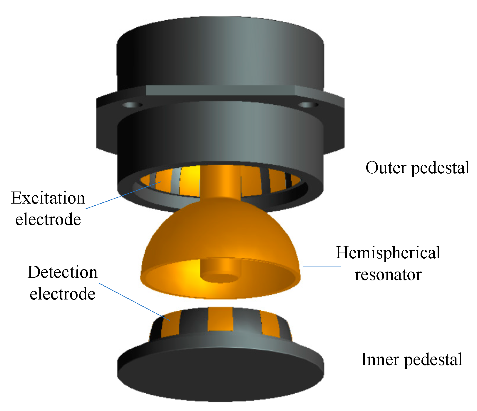
2.1. Basic Structure of HRG
The sensitive element of HRG in force feedback mode is composed of three parts: outer pedestal, hemispherical resonator, and inner pedestal, as shown in Figure 1. Sixteen excitation electrodes are evenly distributed on the inner surface of the outer pedestal, which are used for the amplitude, quadrature, and rate control of resonator. Eight detection electrodes are evenly distributed on the outer surface of the inner pedestal, which are used to detect the frequency, amplitude, azimuth of the standing wave, and orthogonal vibration component of the resonator. The geometric structure of the resonator is shown in Figure 2.
Figure 1.
Structure of a hemispherical resonance gyroscope (HRG).
Figure 2.
Sectional view of a hemispherical resonator.
In this section, the equations of motion of a hemispherical resonator containing the first–third harmonics of mass imperfection under the second-order vibration mode are established using the Lagrange mechanics principle and the theory of elastic thin shell.
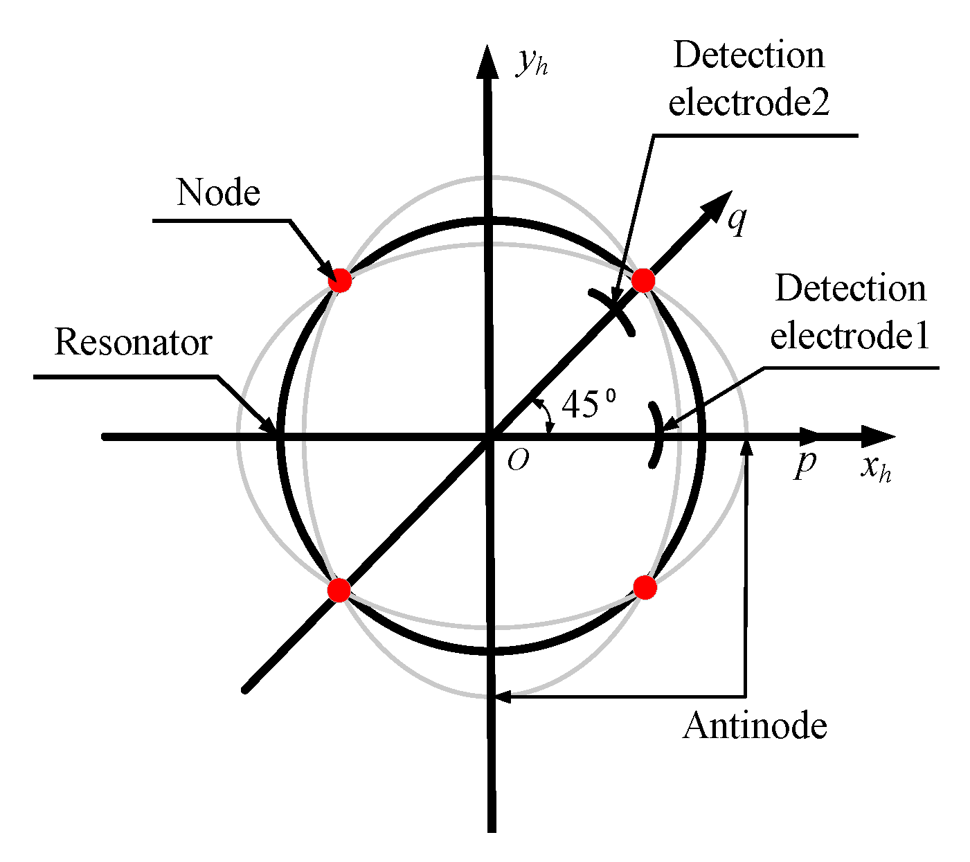
2.2. Establishment of Coordinate Systems of Hemispherical Resonator
Orthogonal Curvilinear Coordinate SystemP-αβz: Origin P is located on the mid-surface of the resonator, axis z is the normal line of the mid-surface, and axes α and β are mutually orthogonal tangent lines located on the mid-surface.
Hemispherical Resonator Coordinate SystemO-xhyhyh: Origin O is at the center of the ground opening of the resonator. Axis zh is coincident with the symmetry axis of the resonator. Axes xh and yh are perpendicular and lying on the ground opening plane of the resonator.
Local Coordinate SystemP-e1e2m: Origin P is located on the mid-surface of the resonator, while axes e1, e2, and m are parallel to the tangential lines α, β, and z, respectively.
Rotating Coordinate SystemO-xryrzr: Origin O is at the center of the ground opening of the resonator, while axes xr, yr, and zr are parallel to the axes e1, e2, and m, respectively.
The attitude matrix from O-xhyhzh to P-e1e2m is described as
The mid-surface deformation and shell stress of a hemispherical resonator are shown in Figure 3a,b. In addition, the defined coordinate systems are also shown in Figure 3a,b.
Figure 3.
(a) Mid-surface deformation of a hemispherical resonator; (b) Stress of hemispherical thin shell microelement.
2.3. Deformation Energy of Hemispherical Resonator
The deformation equations of the mid-surface of a hemispherical resonator are obtained as follows [29]:
where εα and εβ are the normal strains of the mid-surface in the directions α and β. γαβ is the shear strain on the αβ plane determined by coordinate tangential lines α and β. κ1 and κ2 are the principal curvature of the mid-surface along the directions α and β. χ is the twist rate of the mid-surface. R is the curvature radius of the mid-surface, as shown in Figure 3.
The strains of the point with the displacement z from the mid-surface of a hemispherical resonator are expressed as follows [30]:
The relationships between stress and strain displacement z from the mid-surface of a hemispherical resonator by Hooke’s law [30] are given by
where E and μ are the Young’s modulus and the Poisson’s ratio of the resonator, respectively. and are the normal stress and shear stress of the mid-surface in the α direction, respectively. Similarly, and are the normal stress and shear stress of the mid-surface in the β direction, respectively, as shown in Figure 3b.
The deformation energy [30] of a hemispherical resonator is written as
where h is the thickness of the resonator, as shown in Figure 2.
The vibration amplitude of a resonator under the second-order vibration mode is only a few micrometers. Thus, the assumption that the mid-surface is not stretchable can be applied; then,
Substituting Equations (2)−(4) into Equation (5), the approximate deformation energy of a hemispherical resonator is described as
2.4. Second-Order Vibration Mode Function
When the hemispherical resonator works in the second-order vibration mode, the displacements of a point on the mid-surface are denoted as follows [16]:
where U(α), V(α), and W(α) are Raleigh’s functions, which restrict the displacement relationship among different microelements of the resonator. p(t) and q(t) are time-dependent harmonic oscillation functions, which reveal the amplitude, frequency, and phase information of vibration, and their directions are shown in Figure 4.
Figure 4.
Second-order mode decomposition.
Substituting Equation (8) into Equations (2) and (6), the differential equations are as follows:
By solving the differential equations, Raleigh’s functions are given by
When central attention is paid to the form of Raleigh’s functions rather than their amplitudes, C1 = 1 can be considered.
2.5. Kinetic Energy of Hemispherical Resonator
When a hemispherical resonator works in the second-order vibration mode, point P on the mid-surface will move to ; the vector M in the rotating coordinate system O-xryrzr is expressed as
The absolute velocity of a point on the mid-surface of a hemispherical resonator is written as
where , , and are the first time derivatives of u, v, and w, respectively.
The approximate kinetic energy of a hemispherical resonator is obtained by
where ρ is the density of the resonator, which is related to the circumferential angle.
The density ρ is expanded in the form of a Fourier series,
where ρ0 is average density, while εi and βi are the relative amplitude and azimuth of the i-th harmonic of density imperfection, respectively.
2.6. Equations of Motion of Hemispherical Resonator Containing First–Third Harmonics of Mass Imperfection
It is known from the orthogonality of the trigonometric function system that, for integers i and j,
Substituting Equations (8), (14), and (15) into Equation (13), the kinetic energy of a hemispherical resonator is rewritten as
where and are the first-order time derivatives of p and q, respectively. Similarly, and are the second-order time derivatives.
Applying Equations (8), (14), and (15) into Equation (7), the deformation energy of a hemispherical resonator is rearranged as
where
The Lagrange function of the second-order vibration mode of a hemispherical resonator is given by
The second-order vibration mode is governed by the Lagrange equations
where the energy dissipation function is
where ξp = ξq = ξ is the viscous damping coefficient of the hemispherical resonator. Fp and Fq are the external forces applied on the resonator. If the resonator is in an accelerated state, then
where Fp-e and Fq-e are the electrostatic forces, while Fp-i and Fq-i are the inertia forces.
The inertia forces of a hemispherical resonator are described by
where ap, aq, and mh are the acceleration and equivalent mass of the resonator, respectively.
The equations of motion of a hemispherical resonator under the second-order vibration mode are written as
where
where fp and fq are the electrostatic-specific forces, while gp and gq are the inertia-specific forces. Under ideal conditions, cp = cq = c.
Equation (27) is the natural angular frequency of an ideal hemispherical resonator. Based on the basic parameters of the resonator in Table 1, the natural angular frequency ω0 = 12,393.6 rad/s, and its corresponding natural frequency f0 = 1972.5 Hz.
Table 1.
Geometric and physical parameters of resonator made of fused quartz.
The relative damping coefficient of a hemispherical resonator is defined as follows [31]:
The quality factor of a hemispherical resonator can be expressed as follows [31]:
Substituting Equation (29) into Equation (28) yields
Applying Equation (30) into Equation (25), the equations of motion of a hemispherical resonator under the second-order vibration mode are finally written as
Equation (31) is the basis of the error mechanism analysis of a hemispherical resonator containing the first–third harmonics of mass imperfection under linear vibration excitation.
3. Effect of Linear Vibration on Standing Wave of Imperfect Hemispherical Resonator
In this section, the binding problems of a standing wave of a hemispherical resonator containing the first–third harmonics of mass imperfection are analyzed under linear vibration excitation.
3.1. Effect of Vertical Linear Vibration on Standing Wave of Imperfect Hemispherical Resonator
As shown in Figure 2, the hemispherical resonator is subjected to linear vibrations in the x-, y-, and z-directions. The first choice is to analyze the influence of vertical linear vibration on the standing wave of a hemispherical resonator.
The linear vibration of a hemispherical resonator in the zh axis direction is expressed as
where z0 and λ represent the vibration amplitude and frequency of the resonator, respectively.
The linear acceleration in the zh axis direction is obtained by
The linear acceleration in the zh axis direction is projected into the local coordinate system P-e1e2m as
The equations of motion of a hemispherical resonator under linear vibration excitation in the zh axis direction are given by
where
Substituting Equations (14), (34), and (36) into Equation (35) yields
where
The steady-state response of Equation (36) can be represented by
where a, m, b, and n are the amplitude parameters of the steady-state response of the vibration system.
Substituting Equation (40) into Equation (37), when λ = ω0, the parameters of vibration amplitude are obtained by
where G/M = −0.4 on the basis of the parameters in Table 1.
Substituting Equation (40) into Equation (8), the radial vibration of a hemispherical resonator is expressed as
where
where ϑ represents the azimuth of the antinode of the standing wave relative to the initial position, as shown in Figure 5.
Figure 5.
Azimuth of a standing wave.
Substituting Equation (41) into Equation (43), the azimuth of a standing wave is obtained by
Equation (44) shows that the standing wave is bound in the orientation of the second harmonic of mass imperfection under linear vibration in the zh axis direction.
Substituting Equations (41) and (40) into Equation (8), the steady-state radial vibration is obtained by
3.2. Effect of Horizonal Linear Vibration on Standing Wave of Imperfect Hemispherical Resonator
After analyzing the influence of vertical vibration, the next step is to demonstrate the influence of horizontal vibration on the standing wave of a resonator, where the horizontal linear vibration consists of two directions: xh and yh.
The linear vibration of a hemispherical resonator in the xh axis direction is expressed as
where x0 and λ represent the vibration amplitude and frequency of the resonator, respectively.
The linear acceleration of a hemispherical resonator in the xh axis direction is obtained by
The linear acceleration in the xh axis direction is projected into the local coordinate system P-e1e2m as
The equations of motion of a hemispherical resonator under linear vibration excitation in the xh axis direction are given by
Substituting Equations (14), (36), and (48) into Equation (49) yields
where
According to Equations (51)–(53), it can be calculated that
Substituting Equation (54) into Equation (50) yields
Substituting Equation (40) into Equation (55), when λ = ω0, the parameters of vibration amplitude are obtained by
where (A + B + C)/M = −0.23 on the basis of applying the parameters in Table 1.
Substituting Equation (56) into Equation (43), the azimuth of a standing wave is obtained by
Equation (57) shows that the standing wave is bound in the orientation of the first and third harmonics of mass imperfection under linear vibration excitation in the xh axis direction.
Substituting Equations (56) and (40) into Equation (8), the steady-state radial vibration of a resonator is given by
The linear vibration of a hemispherical resonator in the yh axis direction is expressed as
where y0 and λ represent the vibration amplitude and frequency of the resonator, respectively.
The linear acceleration in the yh axis direction is obtained by
The linear acceleration in the yh axis direction is projected into the local coordinate system P-e1e2m as
The equations of motion of a hemispherical resonator under linear vibration excitation in the yh axis direction are given by
Substituting Equations (14), (36), and (61) into Equation (62) yields
Substituting Equation (40) into Equation (63), when λ = ω0, the parameters of vibration amplitude are obtained by
Substituting Equation (64) into Equation (43), the azimuth of a standing wave is obtained by
Equation (65) shows that the standing wave is bound in the orientation of the first and third harmonics of mass imperfection under linear vibration excitation in the yh axis direction.
Substituting Equations (64) and (40) into Equation (8), the steady-state radial vibration of a resonator is expressed by
4. Identification of Location of First–Third Harmonics of Mass Imperfection by Linear Vibration
In this section, the identification method for the locations of the first–third harmonics of mass imperfection of a hemispherical resonator by vertical and horizontal vibration is proposed.
4.1. Identification for Location of the Second Harmonic of Mass Imperfection by Vertical Vibration
Under vertical linear vibration excitation, the radial vibration of the bottom (α = π/2) of a resonator at β = 0 and β = π/4 can be expressed by
The azimuth of the second harmonic of mass imperfection of a resonator is obtained by
4.2. Calibration for Locations of the First and Third Harmonics of Mass Imperfection by Horizontal Vibration
Under horizontal linear vibration excitation, the radial vibration of the bottom (α = π/2) of a resonator at β = 0 and β = π/4 can be expressed as
In order to identify the locations of the first and third harmonics of mass imperfection, the resonator is rotated 90°; then, the radial vibration of the resonator under horizontal linear vibration excitation can be described by
Similarly, according to Equation (70), the radial vibration of the bottom (α = π/2) of a resonator at β = 0 and β = π/4 can be expressed as
By solving Equations (69) and (71), the azimuth of the first harmonic of mass imperfection of a resonator is given by
Similarly, the azimuth of the third harmonic of mass imperfection of a resonator is obtained by
5. Numerical Simulation Results
Here, the standing wave binding phenomenon of a hemispherical resonator containing the first–third harmonics of mass imperfection and the location identification method of mass imperfection are verified using a numerical simulation model of the vibration system, which is based on the equations of motion and radial vibration displacement of a resonator.
The radial displacement detection of a resonator is usually completed by two detection electrodes, which are positioned at 0° and 45° in the circumferential direction of the resonator, as shown in Figure 4. The surfaces of both electrodes are metalized with a thin platinum coating. Similarly, the inner surface of the resonator is also metallized with a thin platinum coating. A capacitor is formed between the resonator and electrodes. Thus, the change in radial vibration displacement of the resonator can be reflected by the change in capacitance.
The signals detected by sensors 1 and 2 can be expressed by
The output signals of the displacement detection electrodes can be demodulated by the reference signal sinλt; then, the following equation can be obtained:
where and represent the demodulated signals.
The demodulated signals need to be filtered by the low-pass filter, for which the order and pass band edge frequency are set to 2 and 20 rad/s in the numerical simulation model of the vibration system, respectively.
The basic parameters of the numerical simulation model are as follows: x0 = y0 = z0 = 1 mm, ε1 = ε2 = ε3 = 10−6, β1 = 88.3°, β2 = 16.2°, β3 = 6.0°, λ = ω0 = 1972.5 Hz, Qf = 106, G/M = −0.4, (A + B + C)/M = −0.23. The numerical simulation results are shown in Figure 6 and Figure 7.
Figure 6.
Standing wave binding of a hemispherical resonator containing the first–third harmonics of mass imperfection under linear vibration.
Figure 7.
Location identification of the first–third harmonics of mass imperfection of a hemispherical resonator under linear vibration.
Figure 6a–c indicate the correctness of the azimuth of the standing wave derived from the equations of motion of a hemispherical resonator with mass imperfection under linear vibration.
As shown in Figure 7a–c, the numerical simulation model based on the equations of motion of an imperfect resonator can verify the correctness of the identification method for the locations of the first–third harmonics of mass imperfection.
6. Conclusions
In order to analyze the influence of the first–third harmonics of mass imperfection on the vibration characteristics of a hemispherical resonator, the equations of motion of a resonator containing the first–third harmonics of mass imperfection under linear vibration excitation were established using the elastic thin shell theory and the Lagrange mechanics principle. Through dynamic analysis, it can be concluded that, when the frequency of external linear vibration is equal to the natural frequency of the resonator, the standing wave under vertical linear vibration excitation is bound in the azimuth of the second harmonic of mass imperfection; similarly, the standing wave is bound in the azimuth of the first and third harmonics of mass imperfection under horizontal linear vibration excitation, which indicates that linear vibration excitation can cause a parasitic component to be hidden in the azimuth of the standing wave, which can cause the output signal distortion of the gyroscope. Therefore, it is very important to identify the position of the first - third harmonics of mass imperfection. According to the binding phenomenon of standing wave, vertical linear vibration can be used to calibrate the location of the second harmonic of mass imperfection, and horizontal linear vibration can be used to determine the locations of the first and third harmonics of mass imperfection, which can provide a theoretical method for the mass balance of an imperfect resonator.
Author Contributions
Conceptualization, Y.H.; data curation, Y.H.; formal analysis, Y.H. and Z.W.; funding acquisition, S.R.; investigation, Y.H. and Z.W.; methodology, Y.H.; software, Y.H.; supervision, S.R.; writing—original draft, Y.H.; writing—review and editing, S.R. and G.Y. All authors have read and agreed to the published version of the manuscript.
Funding
This research was funded by the Pre-Research Fund during the “13th Five-Year Plan”, grant number 41417060101.
Acknowledgments
This work was carried out at the Laboratory of the Inertial Technology, Space Control, and Inertial Technology Research Center, Harbin Institute of Technology.
Conflicts of Interest
The authors declare no conflict of interest.
References
- Rozelle, D.M. The Hemispherical Resonator Gyro: From Wineglass to the Planets. In Proceedings of the 19th AAS/AIAA Space Flight Mechanics Meeting, Savannah, GA, USA, 8–12 February 2009. [Google Scholar]
- Jeanroy, A.; Bouvet, A.; Remillieux, G. HRG and marine applications. Gyroscopy Navig. 2014, 5, 67–74. [Google Scholar] [CrossRef]
- Meyer, A.D.; Rozelle, D.M. Milli-HRG inertial navigation system. Gyroscopy Navig. 2012, 3, 24–29. [Google Scholar] [CrossRef]
- Emily, L.B.; Allan, Y.L. In-Flight Characterization of Cassini Inertial Reference Units, AIAA Guidance, Navigation and Control Conference and Exhibit; AIAA: Hilton Head, SC, USA, 2007. [Google Scholar]
- Lynch, D.D. Vibratory Gyro Analysis by the Method of Averaging. In Proceedings of the 2nd SAINT Petersburg International Conference on Gyroscopic Technology Navigation Part 1, Saint Petersburg, Russia, 24–25 May 1995; pp. 26–34. [Google Scholar]
- IEEE Standard Specification Format Guide and Test Procedure for Coriolis Vibratory Gyros. 2004. Available online: https://ieeexplore.ieee.org/servlet/opac?punumber=9606 (accessed on 8 April 2019).
- Loveday, P.W.; Rogers, C.A. The influence of control system design on the performance of vibratory gyroscopes. J. Sound Vib. 2002, 255, 417–432. [Google Scholar] [CrossRef]
- Fox, C.H.J. A simple theory for the analysis and correction of frequency splitting in slightly imperfect rings. J. Sound Vib. 1990, 142, 227–243. [Google Scholar] [CrossRef]
- Choi, S.Y.; Kim, J.H. Natural frequency split estimation for inextensional vibration of imperfect hemispherical shell. J. Sound Vib. 2011, 330, 2094–2106. [Google Scholar] [CrossRef]
- Basarab, M.A.; Lunin, B.S.; Matveev, V.A.; Chumankin, E.A. Balancing of hemispherical resonator gyros by chemical etching. Gyroscopy Navig. 2015, 6, 218–223. [Google Scholar] [CrossRef]
- Wang, Y.T.; Pan, Y.; Qu, T.L.; Yang, K.Y.; Luo, H. Decreasing Frequency Splits of Hemispherical Resonators by Chemical Etching. Sensors 2018, 18, 3772. [Google Scholar] [CrossRef] [PubMed]
- Gallacher, B.J.; Hedley, J.; Burdess, J.S.; Harris, A.J.; Rickard, A.; King, D.O. Electrostatic correction of structural imperfections present in a micro-ring gyroscope. J. Microelectromech. Syst. 2005, 14, 221–234. [Google Scholar] [CrossRef]
- Schwartz, D.; Dong, J.K.; M’Closkey, R.T. Frequency tuning of a disk resonator gyro via mass matrix perturbation. In Proceedings of the 2008 American Control Conference, Seattle, WA, USA, 11–13 June 2008; Volume 131, pp. 3740–3745. [Google Scholar]
- Xiao, D.; Yu, D.; Zhou, X.; Hou, Z.; He, H.; Wu, X. Frequency Tuning of a Disk Resonator Gyroscope via Stiffness Perturbation. IEEE Sens. J. 2017, 17, 4725–4734. [Google Scholar] [CrossRef]
- Senkal, D.; Ahamed, M.J.; Trusov, A.A.; Shkel, A.M. Achieving Sub-Hz Frequency Symmetry in Micro-Glassblown Wineglass Resonators. J. Microelectromech. Syst. 2014, 23, 30–38. [Google Scholar] [CrossRef]
- Matveev, V.A.; Lipatnikov, V.I.; Alekin, A.V.; Basarab, M.A. Solid Wave Gyroscope; National Defense Industry Press: Beijing, China, 2009. [Google Scholar]
- Shao, P.; Mayberry, C.L.; Gao, X.; Tavassoli, V.; Ayazi, F. A Polysilicon Micro-hemispherical Resonating Gyroscope. J. Microelectromech. Syst. 2014, 23, 762–764. [Google Scholar] [CrossRef]
- Xi, X.; Wu, Y.L.; Zhang, Y.M.; Wu, X.M.; Zheng, Y.; Wu, X.Z. A Simple Acoustic Method for Modal Parameter Measurement of the Resonator for Vibratory Shell Gyroscope. IEEE Sens. J. 2014, 14, 4069–4077. [Google Scholar]
- Hu, X.D.; Luo, J.K.; Yu, B.; Zhou, Q.; Lin, K.; Lei, T.; Fang, Z. Application of ion beam in the mass balancing of hemispherical resonator. In Proceedings of the Fifth Chinese Society of Inertial Technology Annual Conference Proceedings, Guilin, China, 13–17 October 2003; pp. 247–252. [Google Scholar]
- Wan, Q.; Gu, H.; Fan, B.; Zhao, H.; Xu, D.; Guo, S. A High Symmetry Polysilicon Micro Hemispherical Resonating Gyroscope with Spherical Electrodes. In Proceedings of the 2017 IEEE SENSORS, Glasgow, UK, 29 October–1 November 2017; pp. 1–3. [Google Scholar]
- Tao, Y.; Xi, X.; Xiao, D.; Tan, Y.; Cui, H.; Wu, X. Precision balance method for cupped wave gyro based on cup-bottom trimming. Chin. J. Mech. Eng. 2012, 25, 63–70. [Google Scholar] [CrossRef]
- Abdelmoneum, M.A.; Demirci, M.M.; Lin, Y.-W.; Nguyen, C.T.-C. Location-dependent frequency tuning of vibrating micromechanical resonators via laser trimming. In Proceedings of the 2004 IEEE International Frequency Control Symposium and Exposition, Montreal, QC, Canada, 23–27 August 2004; pp. 272–279. [Google Scholar]
- Kim, J.H.; Kim, J.H. Trimming of imperfect hemispherical shell including point mass distributions. Int. J. Mech. Sci. 2017, 131, 847–852. [Google Scholar] [CrossRef]
- Xi, X.; Qu, Y.L.; Wang, D.Y.; Wu, X.M.; Tao, Y.; Wu, X.Z. Investigation on standing wave vibration of the imperfect resonant shell for cylindrical gyro. Sens. Actuators A Phys. 2012, 179, 70–77. [Google Scholar] [CrossRef]
- Wang, X.; Wu, W.; Luo, B.; Fang, Z.; Li, Y.; Jiang, Q. Force to rebalance control of HRG and suppression of its errors on the basis of FPGA. Sensors 2011, 11, 11761–11773. [Google Scholar] [CrossRef] [PubMed]
- Ren, S.Q.; Zhao, H.B. Influence of density error of hemispherical resonator on output accuracy of gyro. J. Chin. Inert Technol. 2011, 19, 364–368. (In Chinese) [Google Scholar]
- Tao, Y.; Xi, X.; Xiao, D.B.; Chen, Z.H.; Tan, Y.Q.; Wu, X.Z. A fast identification method for mode offset angle of cupped wave gyroscope. J. Vib. Eng. 2011, 24, 351–358. [Google Scholar]
- Huo, Y.; Ren, S.Q.; Yi, G.X.; Wang, C.H. Establishment of equations of motion of hemispherical resonator and analysis of frequency split caused by slight mass non-uniformity. Chin. J. Aeronaut. 2020, in press. [Google Scholar] [CrossRef]
- Xu, Z.L. Elasticity, 5th ed.; Higher Education Press: Beijing, China, 2016; pp. 174–193. (In Chinese) [Google Scholar]
- Liu, H.W. Shell Theory; Zhejiang University Press: Hangzhou, China, 1989; pp. 269–271. (In Chinese) [Google Scholar]
- Department of Engineering Mechanics, Tsinghua University. Mechanical Vibration; Mechanical Industry Press: Beijing, China, 1980; pp. 52–152. (In Chinese) [Google Scholar]
© 2020 by the authors. Licensee MDPI, Basel, Switzerland. This article is an open access article distributed under the terms and conditions of the Creative Commons Attribution (CC BY) license (http://creativecommons.org/licenses/by/4.0/).