Enhancement of Diversity in Production and Applications Utilizing Electrolytically Polymerized Rubber Sensors with MCF: The Second Report on Various Engineering Applications


Abstract
1. Introduction
2. Electrical Properties for Normal and Shear Motions
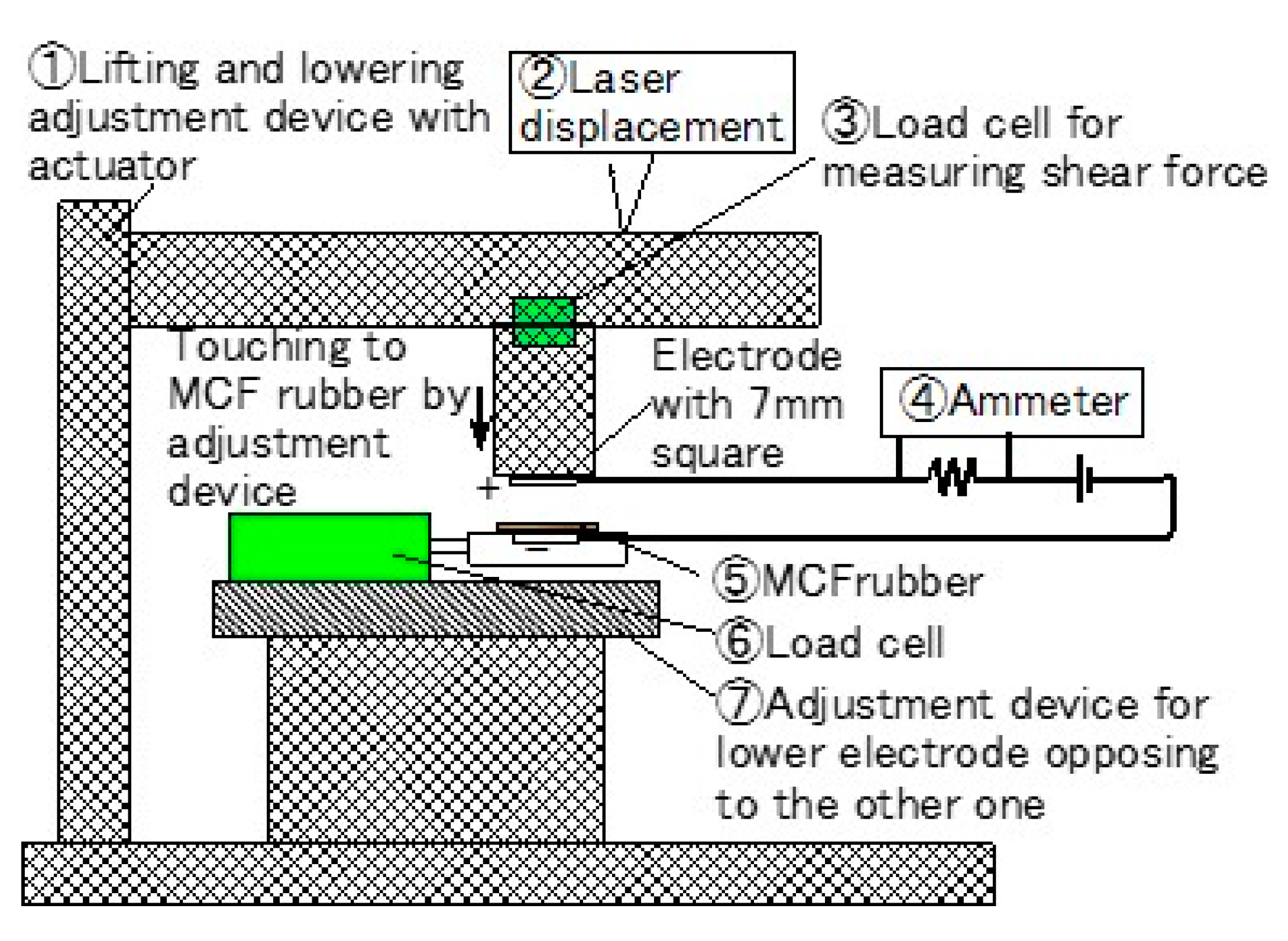
2.1. Compression
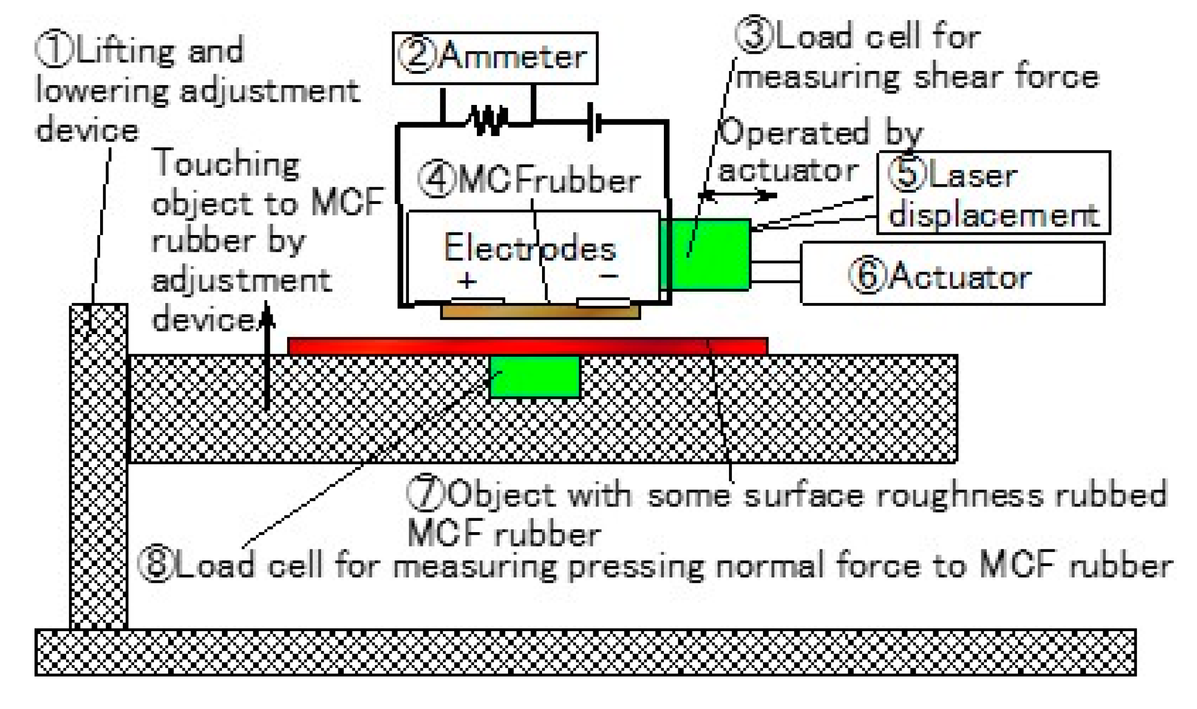
2.2. Shear Motion
3. Electrical Properties of Diverse Object
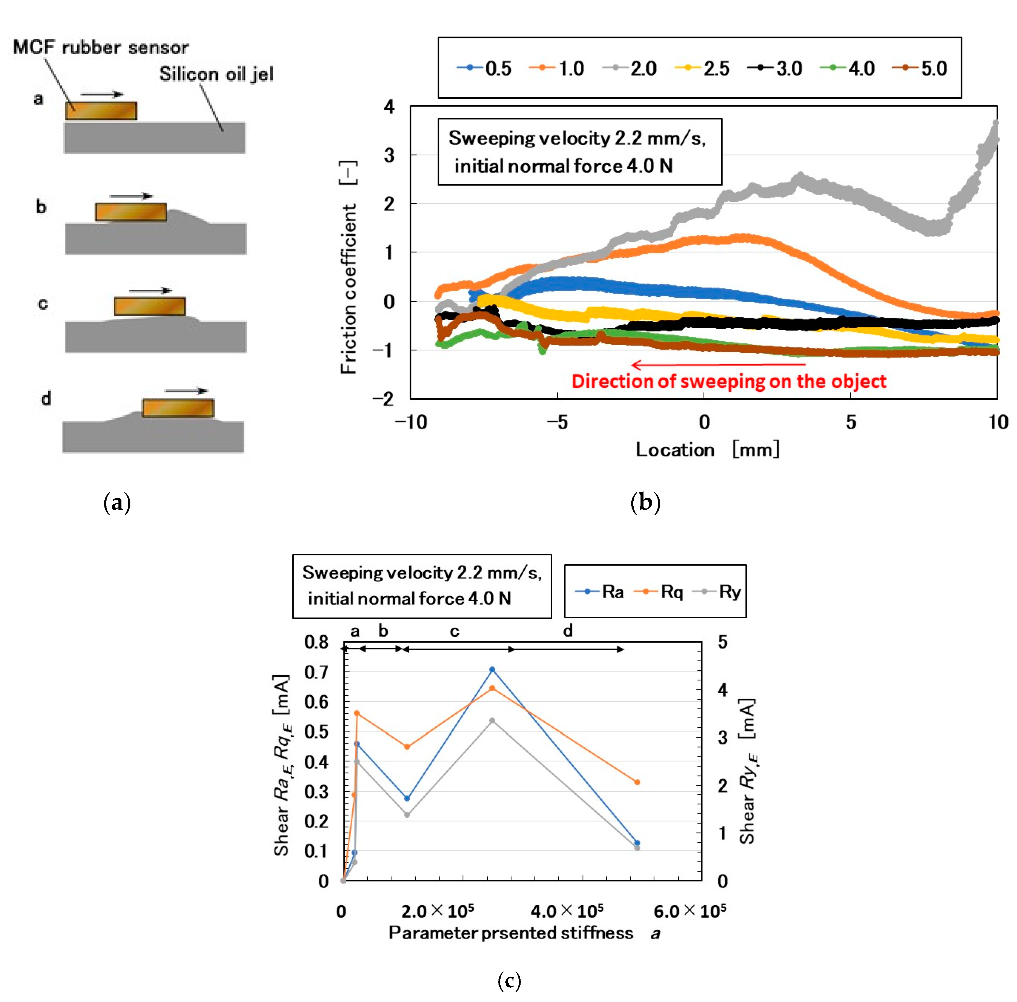
3.1. Soft Object
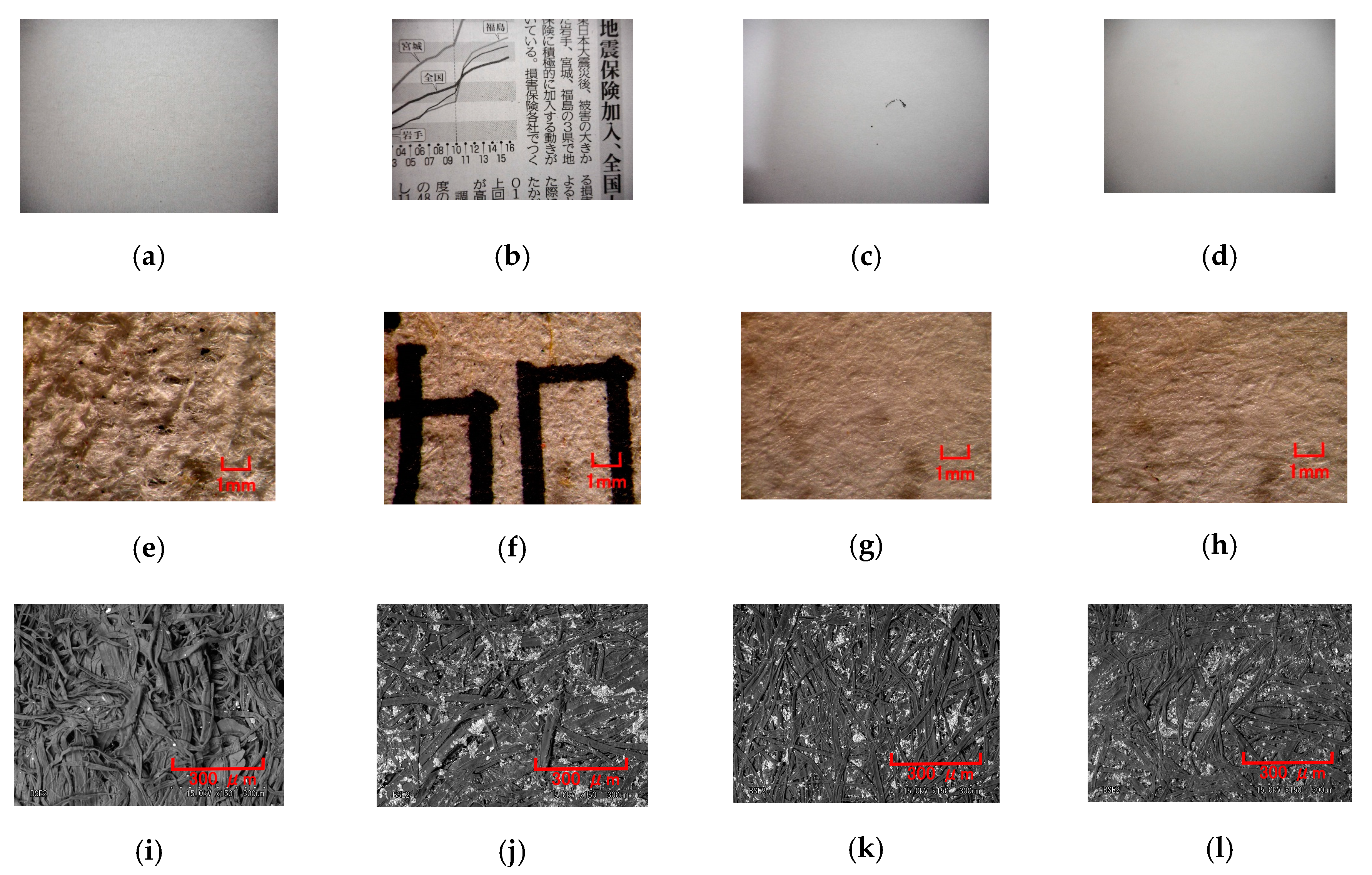
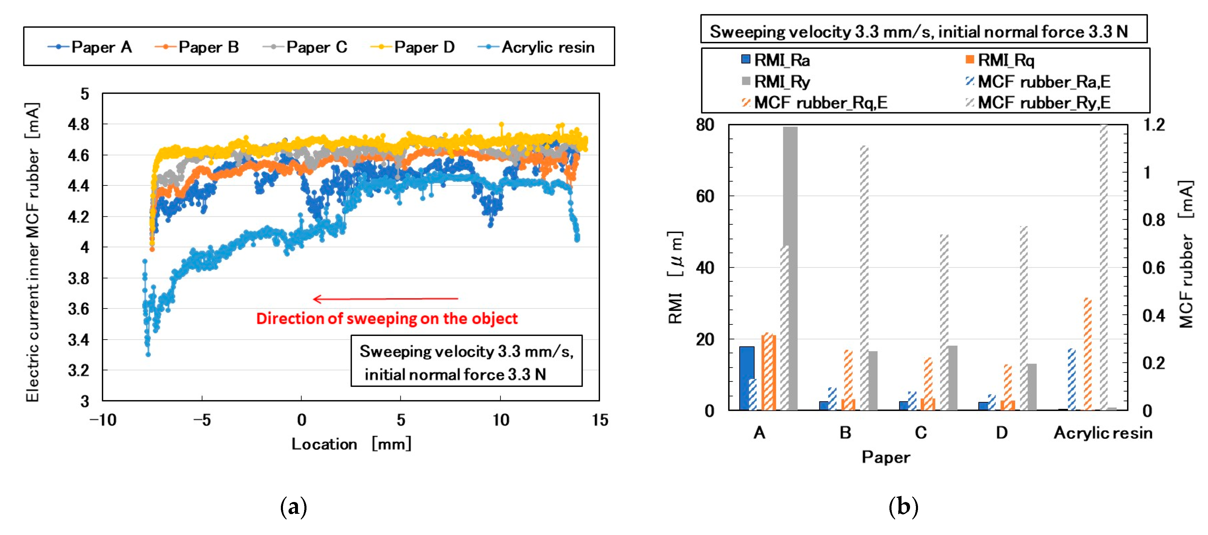
3.2. Paper
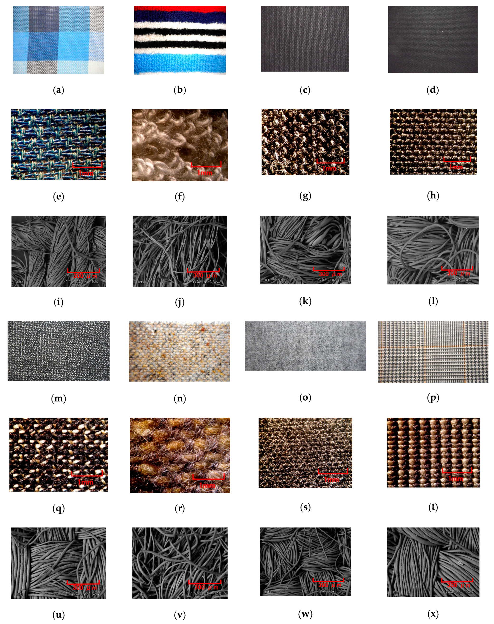
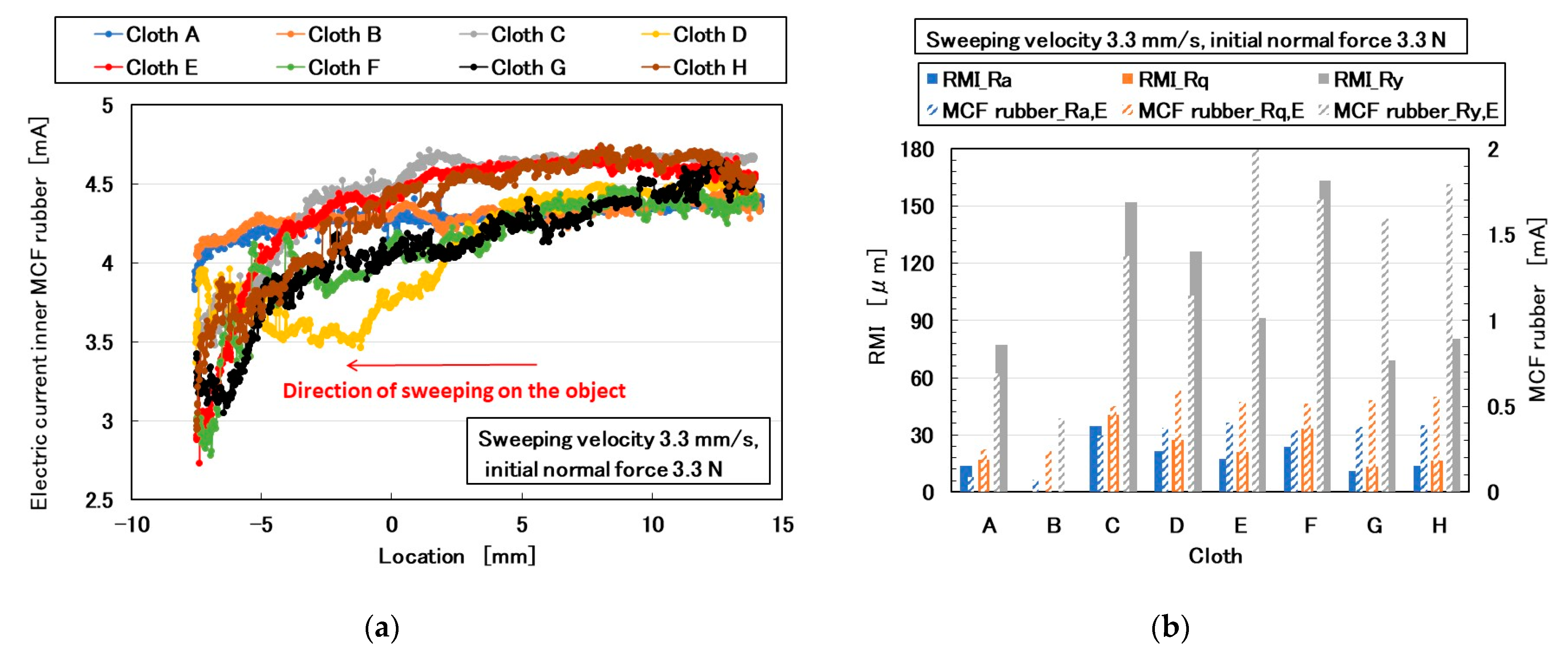
3.3. Cloth
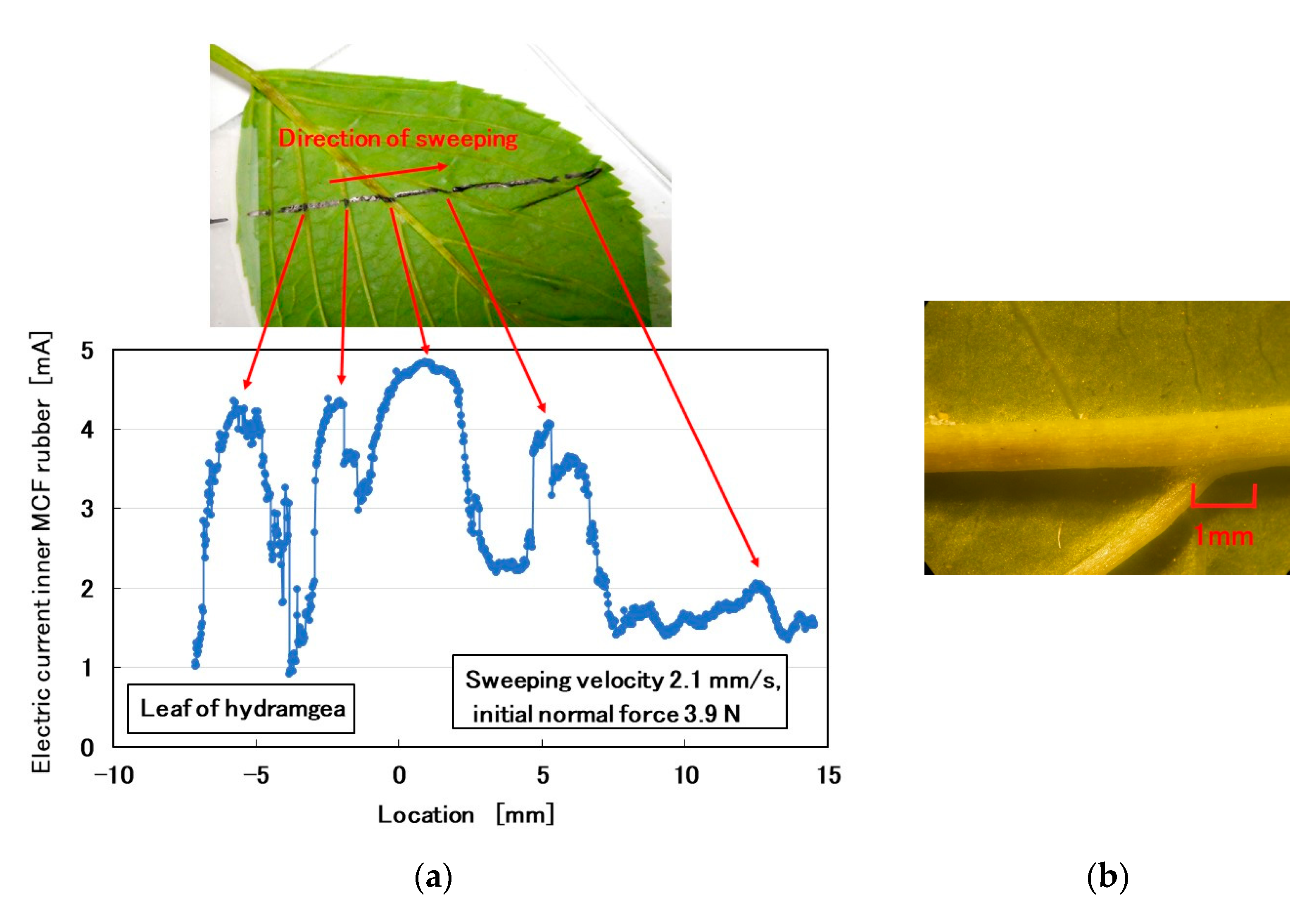
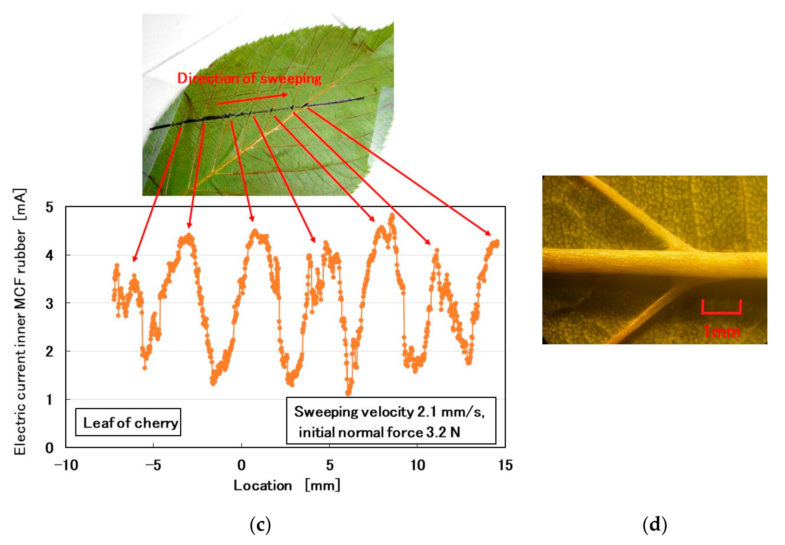
3.4. Plants
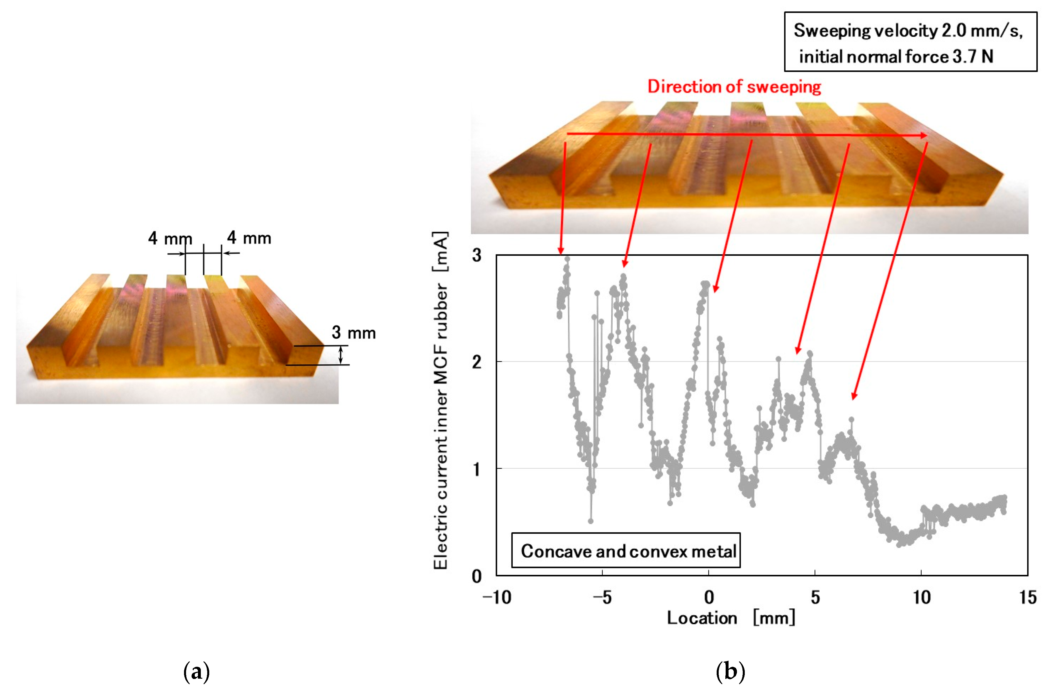
3.5. Large Convexo-Oconcave Body
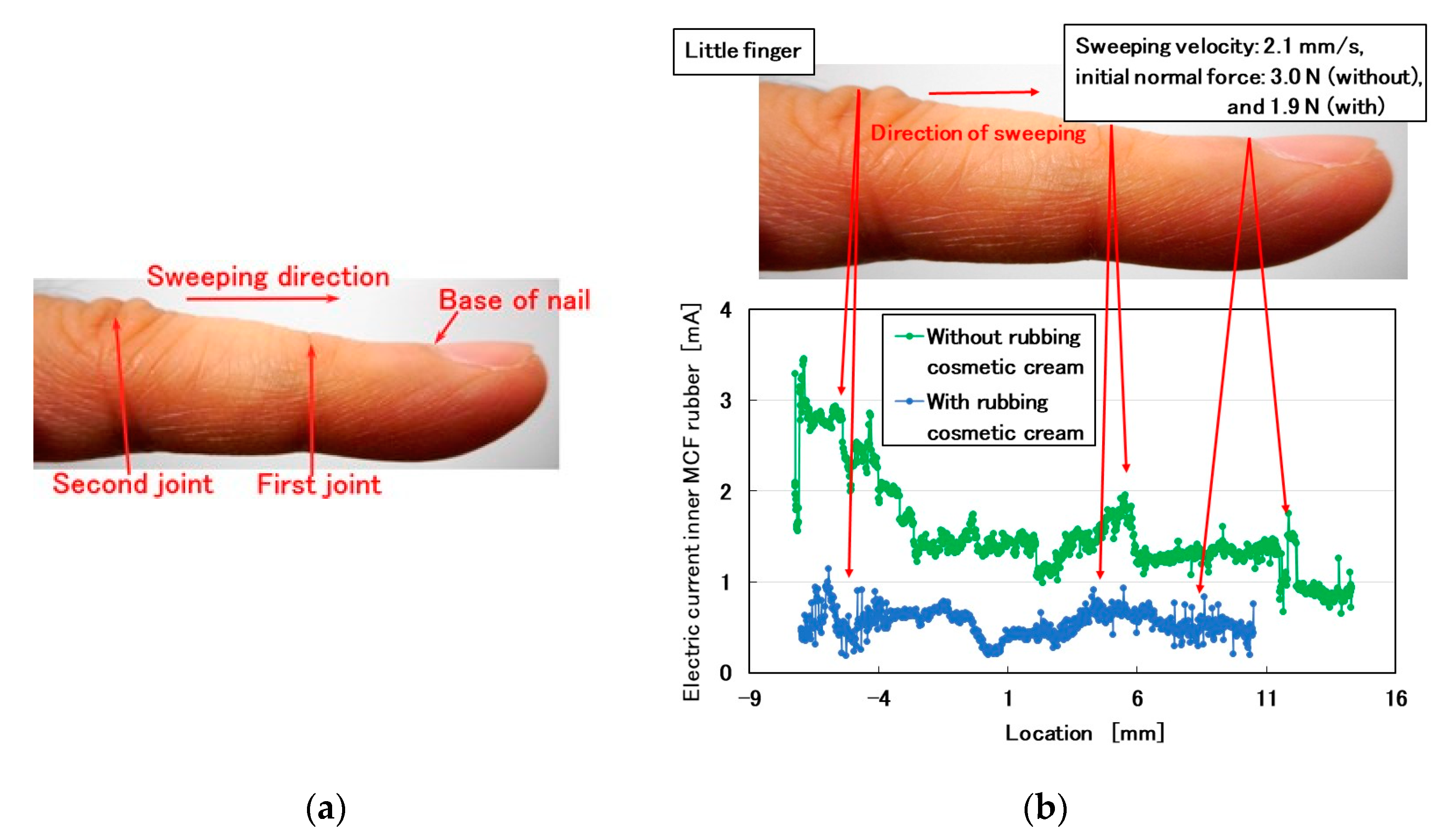
3.6. Cosmetic
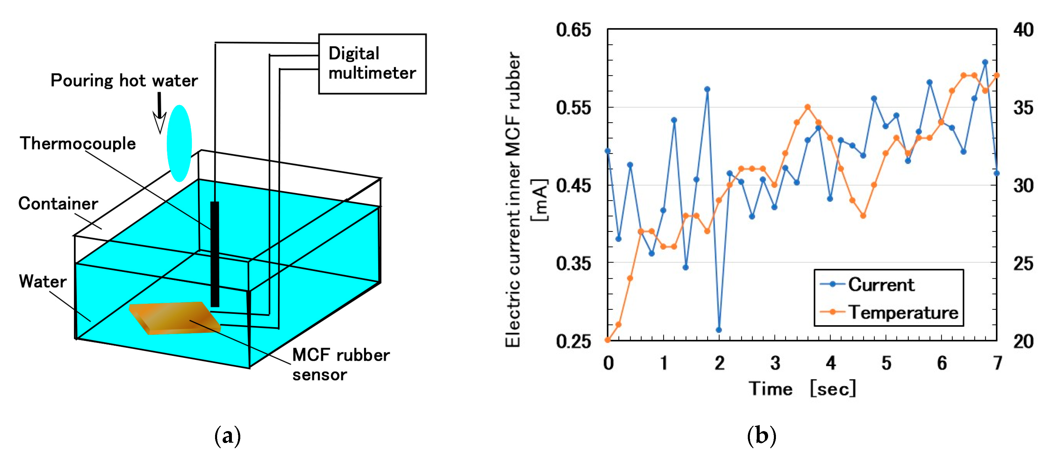
4. Temperature Sensing
5. Conclusions
Author Contributions
Funding
Conflicts of Interest
Appendix A

Appendix B

References
- Shimada, K.; Ikeda, R.; Kikura, H.; Takahashi, H. Enhancement of diversity in production and application utilizing electrolytically polymerized rubber sensors with MCF: The first report on consummate fabrication combining varied kinds of constituents with porous permeant stoking-like rubber. Sensors 2020. To Be Published. [Google Scholar]
- Shimada, K.; Shuchi, S.; Kanno, H.; Wu, Y.; Kamiyama, S. Magnetic cluster and its applications. J. Magn. Magn. Mater. 2005, 289, 9–12. [Google Scholar] [CrossRef]
- Shimada, K.; Kikura, H.; Takahashi, H.; Ikeda, R. Novel adhesion technique using metallic or non-metallic hydrous oxide of metal complexes involving magnetic compound fluid rubber under electrolytic polymerization and magnetic field for producing sensors. Sensors 2019, 19, 689. [Google Scholar] [CrossRef]
- Yoshida, T. The Leading Edge of Development of Super Five Senses Sensor, 1st ed.; NTS Press: Tokyo, Japan, 2005; pp. 253–393. [Google Scholar]
- Nomata, T.; Okuyama, T.; Tanaka, M. Quantification of a constant stimulus applied to infants by diapers–relationship between walking motion and constant stimuli. J. Soc. Appl. Electromagne. Mech. 2011, 19, 330–335. [Google Scholar]
- Liu, W.; Zhang, C.; Lin, H.; Qu, W.; Li, X.; Wang, X. Texture and sliding motion sensation with atriboelectric-nanogenerator transducer. Sens. Actuators A Phys. 2017, 265, 89–94. [Google Scholar] [CrossRef]
- Crowther, J.M. Understanding the effects of topography on skin moisturization measurement via two-dimensional capacitance imaging. Int. J. Cosmetic Sci. 2017, 39, 572–578. [Google Scholar] [CrossRef] [PubMed]
- Gao, Z.; Ishihara, S.; Nakano, S.; Hayakawa, F.; Funami, T.; Koyama, K. Texture evaluation of soft gels with different fractures strains using an artificial tongue. J. Tex. Stud. 2016, 47, 496–503. [Google Scholar] [CrossRef]
- Tsuji, S.; Kohama, T. Using a convolutional neural network to construct a pen-type tactilesensor system for roughness recognition. Sens. Actuators A Phys. 2019, 291, 7–12. [Google Scholar] [CrossRef]
- Tiwana, M.I.; Redmond, S.J.; Lovell, N.H. A review of tactile sensing technologies with applications in biomedical engineering. Sens. Actuators A Phys. 2012, 179, 17–31. [Google Scholar] [CrossRef]
- Dargahi, J. An endoscopic and robotic tooth-like compliance and roughness tactile sensor. Trans. ASME J. Mech. Des. 2002, 8124, 576–582. [Google Scholar] [CrossRef]
- Tanaka, M.; Tanaka, Y.; Chonan, S. Measurement and evaluation of tactile sensations using a PVDF sensor. J. Intell. Mater. Syst. Struct. 2008, 19, 35–42. [Google Scholar] [CrossRef]
- Canepa, G.; Rossi, D.D.; Mageces, G.; Germagnoli, F.; Caiti, A.; Parisini, T. Skin-like tactile sensor arrays for contact stress field extraction. Mater. Sci. Eng. C 1993, 1, 23–36. [Google Scholar]
- Sato, K.; Kawakami, N.; Kamiyama, K.; Tachi, S. Finger-shaped gelforce: Sensor for measuring surface traction fields for robotic hand. IEEE Trans. Haptics. 2010, 3, 37–47. [Google Scholar] [CrossRef] [PubMed]
- Tanaka, M.; Leveque, J.L.; Tagami, H.; Kikuchi, K.; Chonan, S. The “Haptic finger”—A new device for monitoring skin condition. Skin Res. Technol. 2003, 9, 131–136. [Google Scholar] [CrossRef] [PubMed]
- Yabuki, Y.; Tanahashi, K.; Mouri, Y.; Murai, Y.; Togo, S.; Kato, R.; Jiang, Y.; Yokoi, H. Development of new cosmetic gloves for myoelectric prosthetic hand using superelastic rubber. Robot. Autono. Syst. 2019, 111, 31–43. [Google Scholar] [CrossRef]
- Shimada, K.; Saga, N. Development of a hybrid piezo natural rubber piezoelectricity and piezoresistivity sensor with magnetic clusters made by electric and magnetic field assistance and filling with magnetic compound fluid. Sensors 2017, 17, 1521. [Google Scholar] [CrossRef]
- Shimada, K. Elastic MCF rubber with photovoltaics and sensing for use as artificial or hybrid skin (H-Skin): 1st report on dry-type solar cell rubber with piezoelectricity for compressive sensing. Sensors 2018, 18, 1841. [Google Scholar] [CrossRef] [PubMed]
- Shimada, K. Enhancement of MCF rubber utilizing electric and magnetic fields, and clarification of electrolytic polymerization. Sensors 2017, 17, 767. [Google Scholar] [CrossRef] [PubMed]
- Shimada, K.; Saga, N. Mechanical enhancement of sensitivity in natural rubber using electrolytic polymerization aided by a magnetic field and MCF for application in haptic sensors. Sensors 2016, 16, 1521. [Google Scholar] [CrossRef] [PubMed]
- Shimada, K.; Kato, R.; Ikeda, R.; Kikura, H.; Takahashi, H. Gamma-ray irradiation effect on MCF rubber solar cell with both photovoltaics and sensing involving semiconductors fabricated under magnetic and electric fields. World J. Mech. 2020. To Be Submitted. [Google Scholar]


© 2020 by the authors. Licensee MDPI, Basel, Switzerland. This article is an open access article distributed under the terms and conditions of the Creative Commons Attribution (CC BY) license (http://creativecommons.org/licenses/by/4.0/).
Share and Cite
Shimada, K.; Ikeda, R.; Kikura, H.; Takahashi, H. Enhancement of Diversity in Production and Applications Utilizing Electrolytically Polymerized Rubber Sensors with MCF: The Second Report on Various Engineering Applications. Sensors 2020, 20, 4674. https://doi.org/10.3390/s20174674
Shimada K, Ikeda R, Kikura H, Takahashi H. Enhancement of Diversity in Production and Applications Utilizing Electrolytically Polymerized Rubber Sensors with MCF: The Second Report on Various Engineering Applications. Sensors. 2020; 20(17):4674. https://doi.org/10.3390/s20174674
Chicago/Turabian StyleShimada, Kunio, Ryo Ikeda, Hiroshige Kikura, and Hideharu Takahashi. 2020. "Enhancement of Diversity in Production and Applications Utilizing Electrolytically Polymerized Rubber Sensors with MCF: The Second Report on Various Engineering Applications" Sensors 20, no. 17: 4674. https://doi.org/10.3390/s20174674
APA StyleShimada, K., Ikeda, R., Kikura, H., & Takahashi, H. (2020). Enhancement of Diversity in Production and Applications Utilizing Electrolytically Polymerized Rubber Sensors with MCF: The Second Report on Various Engineering Applications. Sensors, 20(17), 4674. https://doi.org/10.3390/s20174674