Fuzzy Logic Type-2 Based Wireless Indoor Localization System for Navigation of Visually Impaired People in Buildings

 , , , and
Abstract
:1. Introduction
2. Materials and Methods
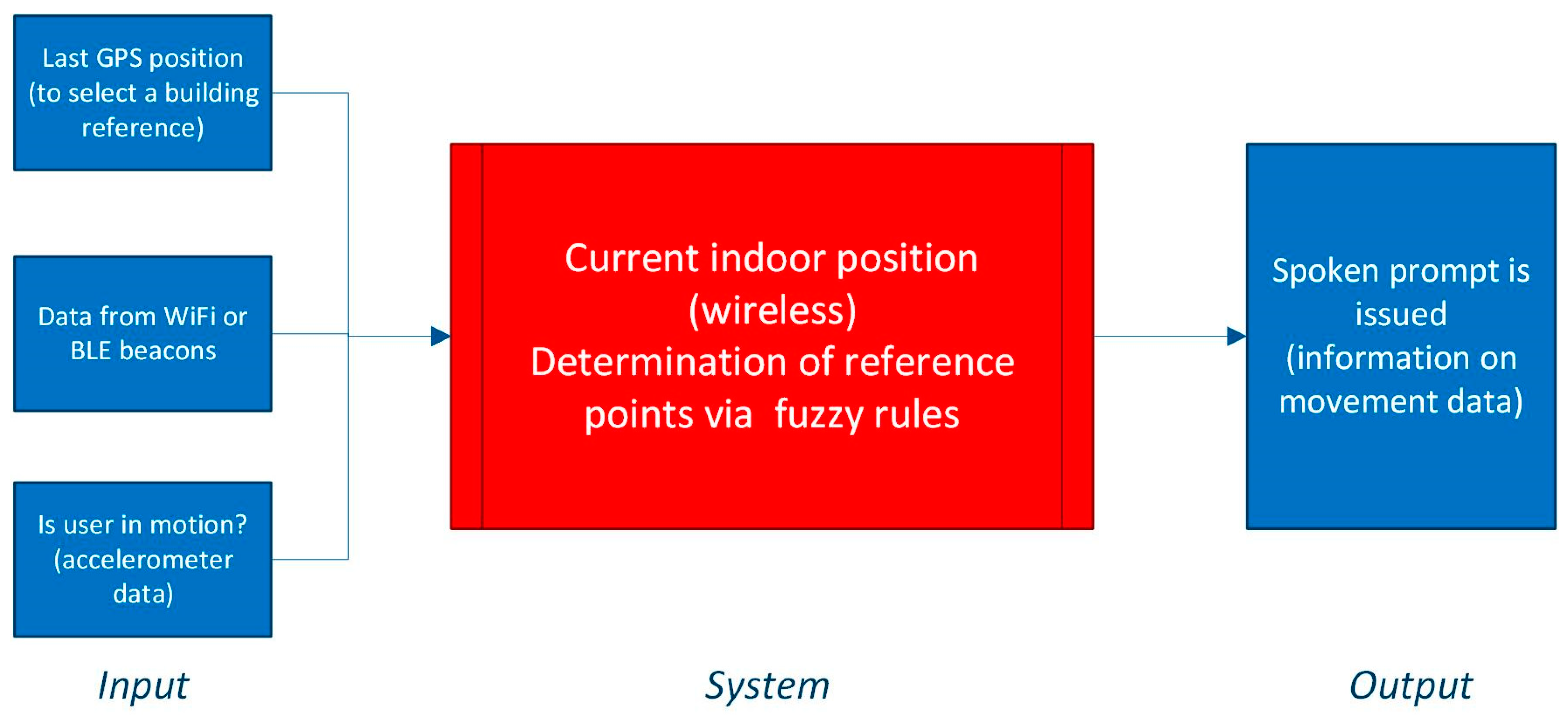
2.1. Model of Indoor Localization
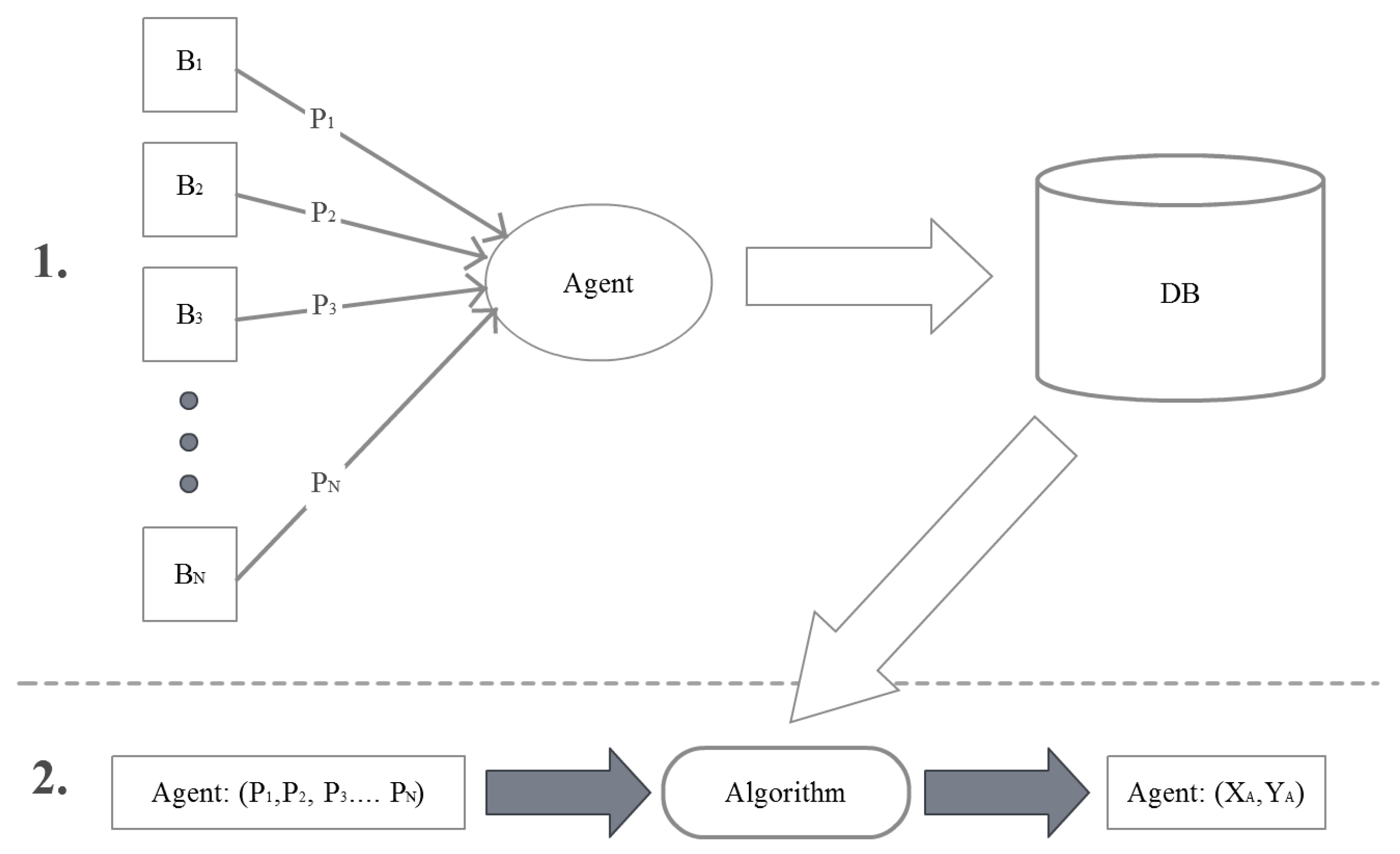
2.2. Fingerprinting Localization
- The stage configuration environment. At this stage, the power signals of all the known active beacons are measured in pre-planned locations. The information collected is stored in a database with reference to the local coordinate space (assigned to specific rooms) or global coordinate space (assigned to a building).
- Step positioning. At this stage, the signal power measurements made over the receiver are compared with the information stored in the database by means of an algorithm. The k-nearest neighbors algorithm is used [58].
2.2.1. K-Nearest Neighbors
2.2.2. Fuzzy Logic Type-1
2.2.3. Fuzzy Logic Type-2
2.3. Evaluation
3. Experiments and Results
3.1. Experiment Setting
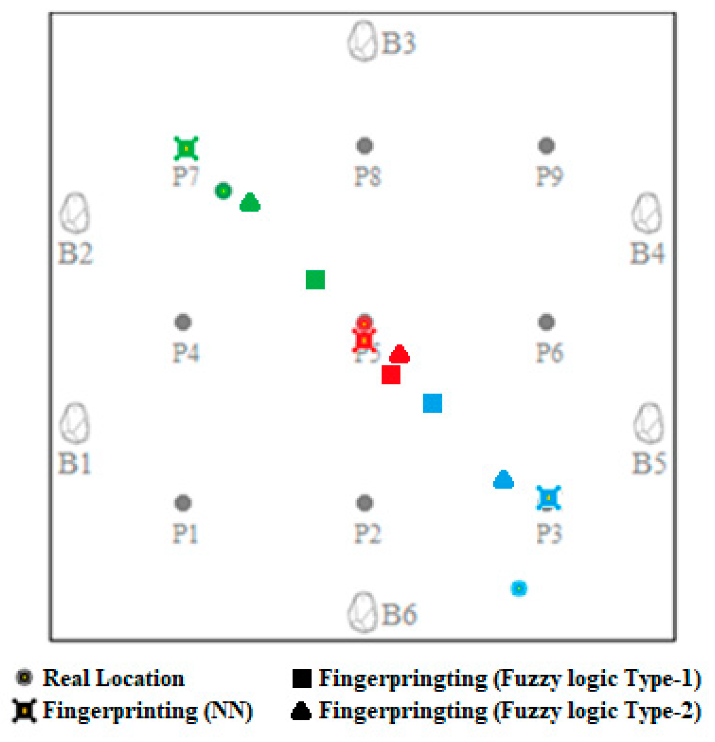
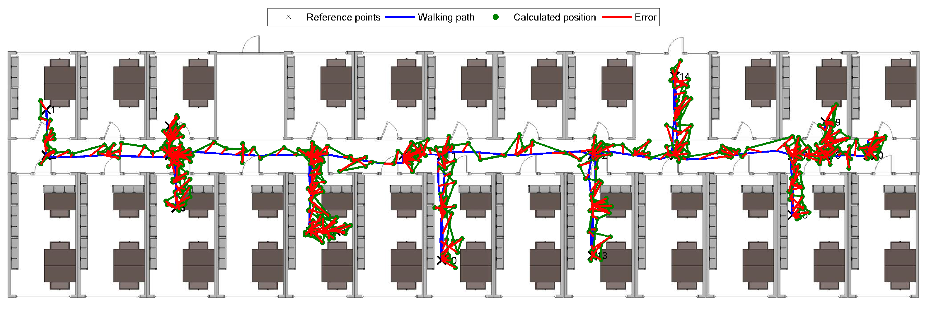
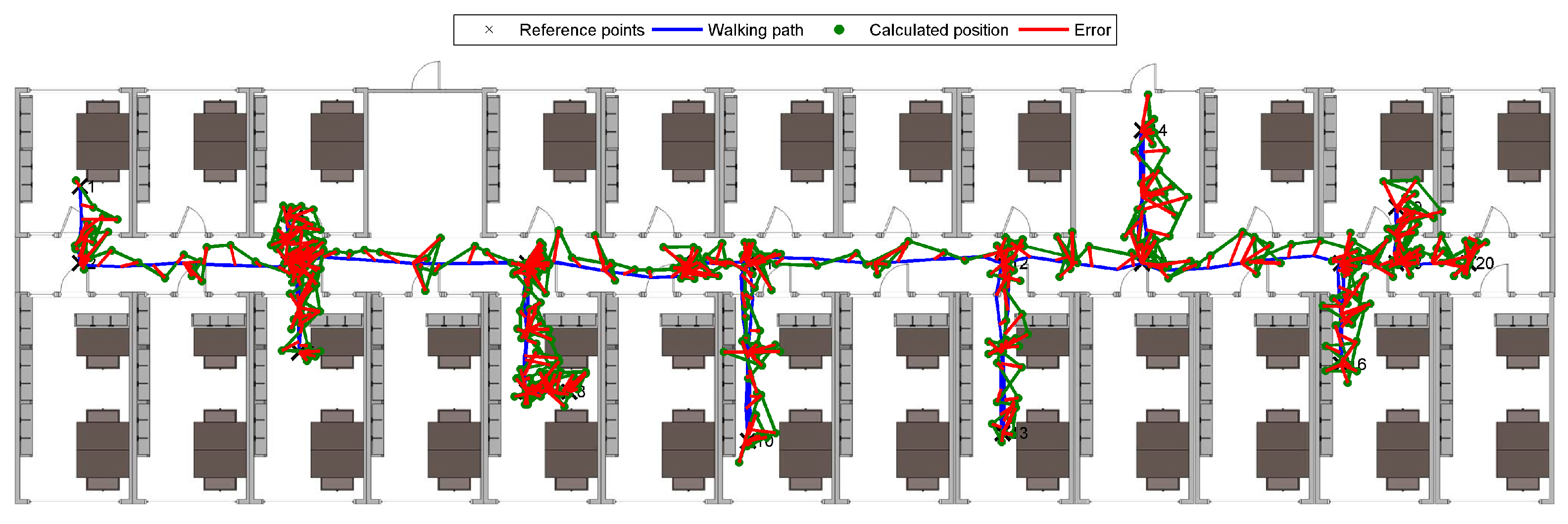
3.2. Results of Fingerprinting Localization
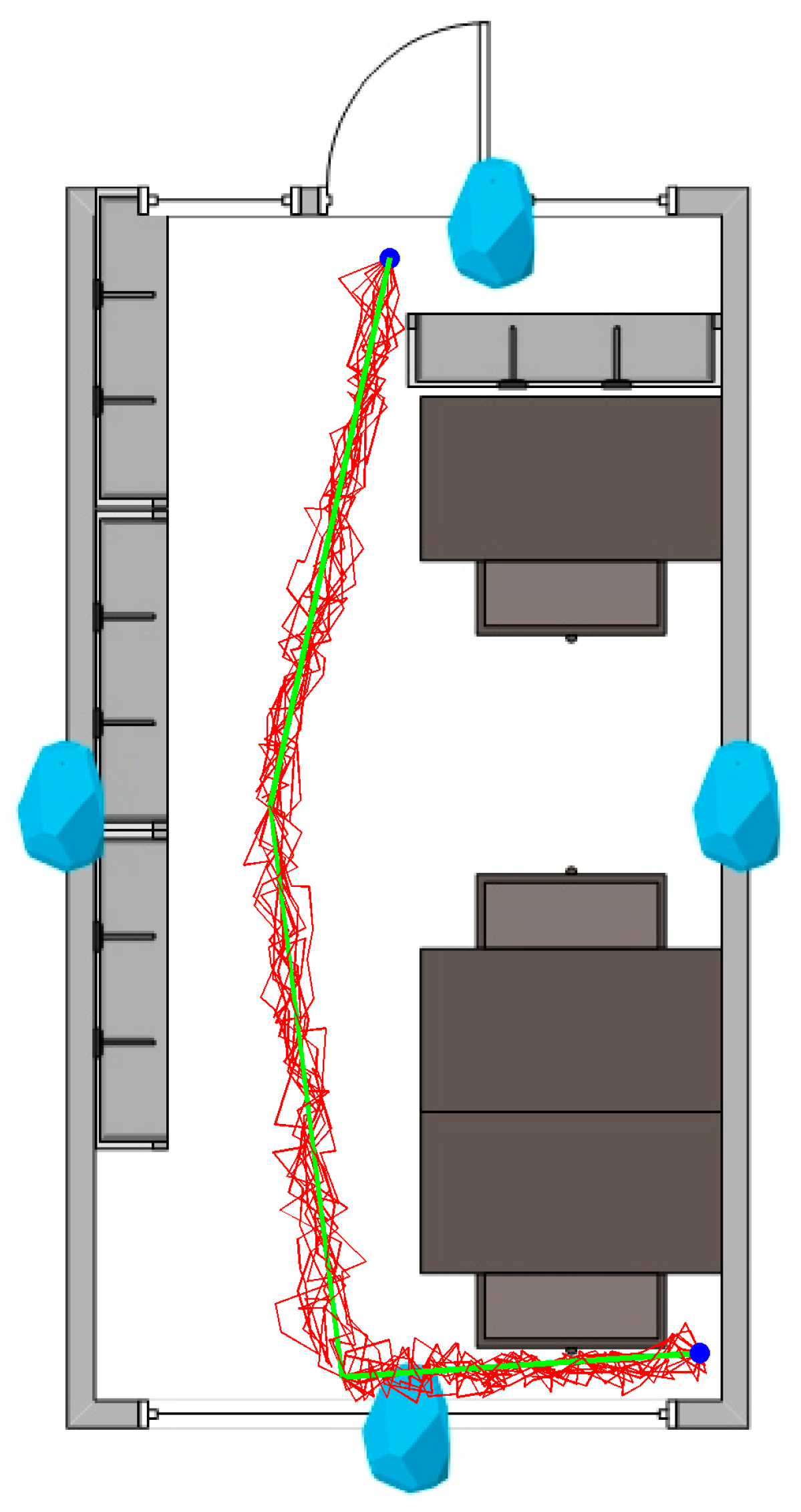
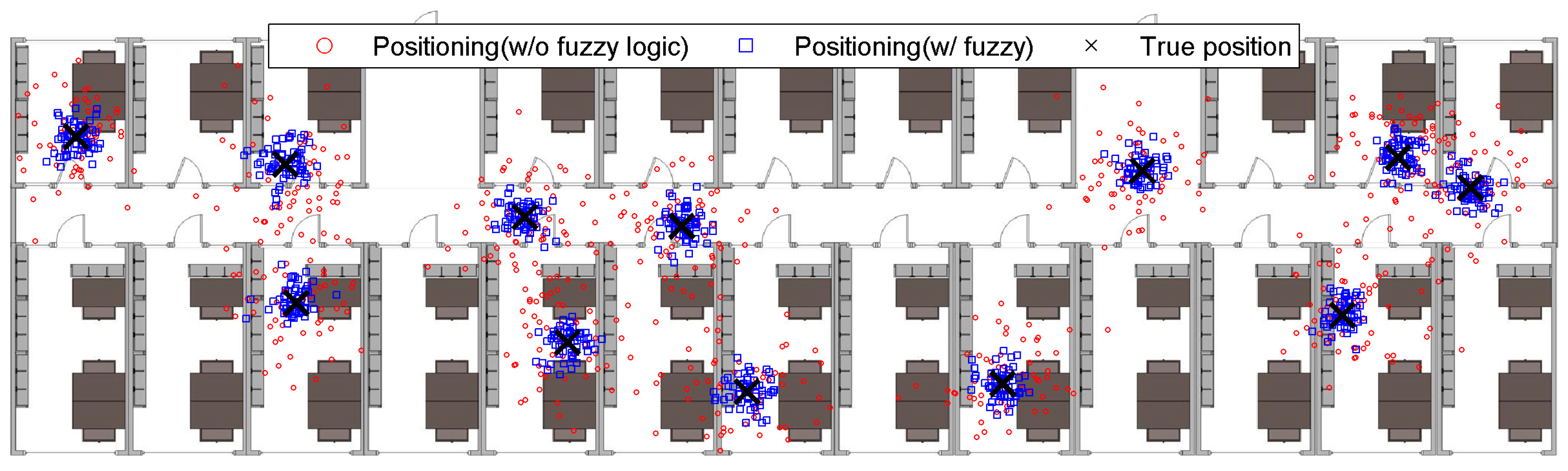
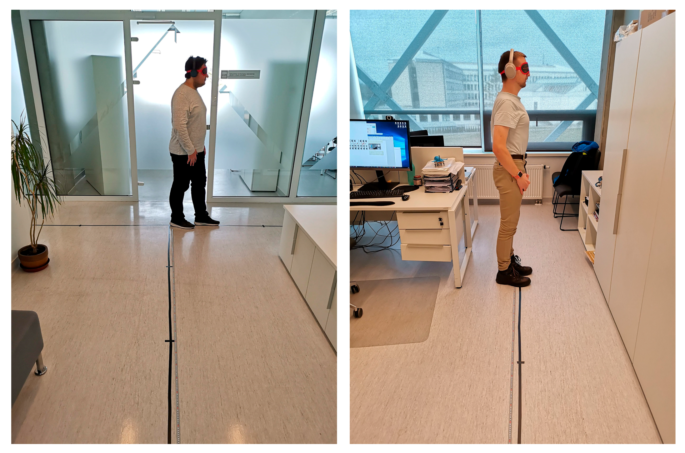
3.3. Real-World Experiment
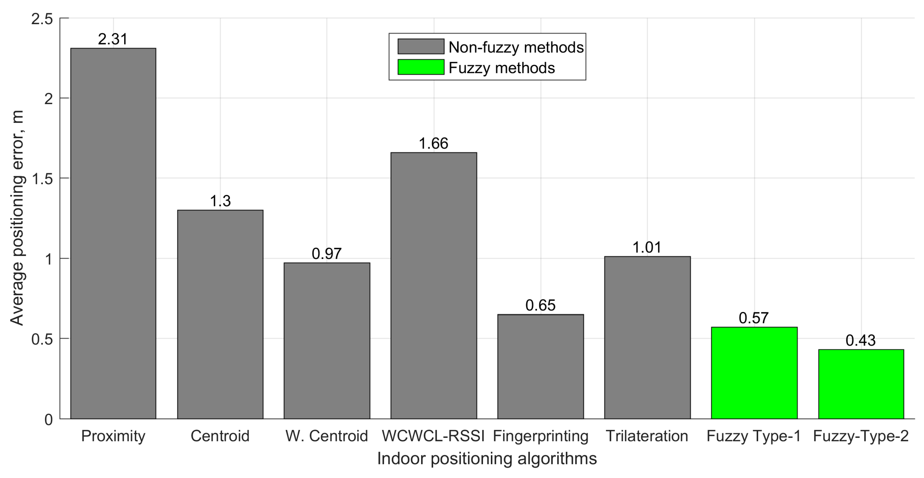
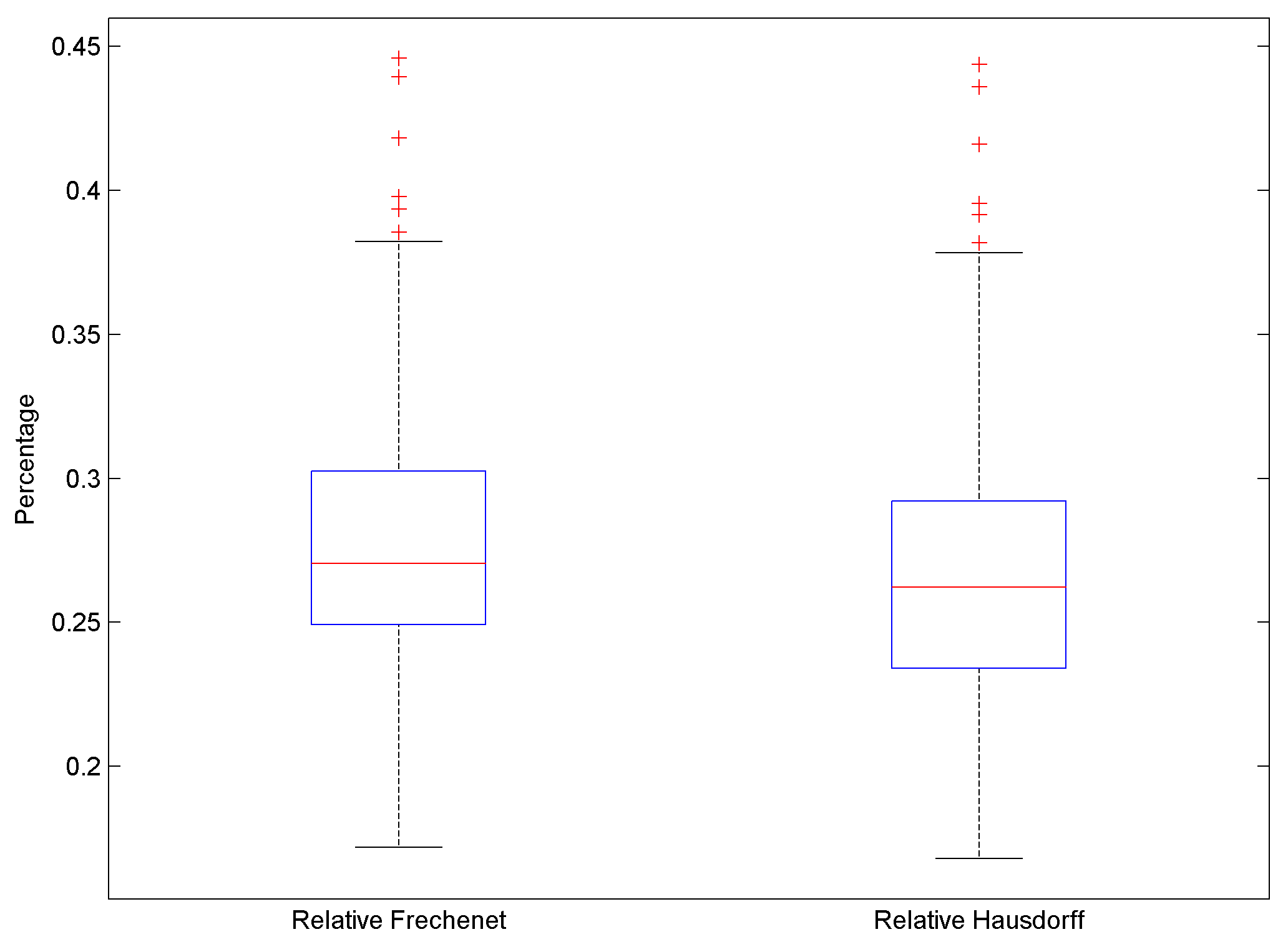
3.4. Evaluation
3.5. Evaluation
4. Concluding Remarks
Author Contributions
Funding
Acknowledgments
Conflicts of Interest
Appendix A
Appendix B
Appendix C

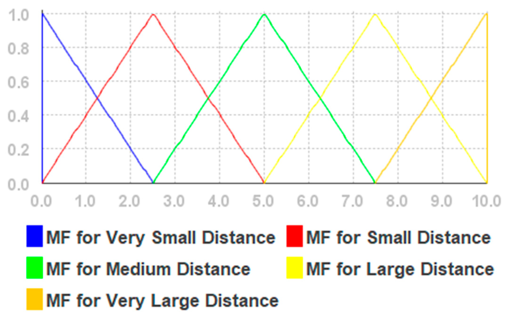
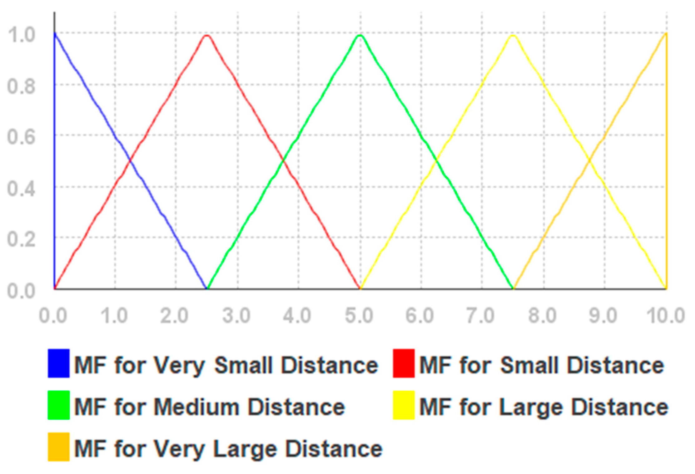
| Linguistic Variables | Membership Function Variable Values |
|---|---|
| Very Small Distance | 0.0→0.0→2.5 |
| Small Distance | 0.0→2.5→5.0 |
| Medium Distance | 2.5→5.0→7.5 |
| Large Distance | 5.0→7.5→10.0 |
| Very Large Distance | 7.5→10.0→10.0 |
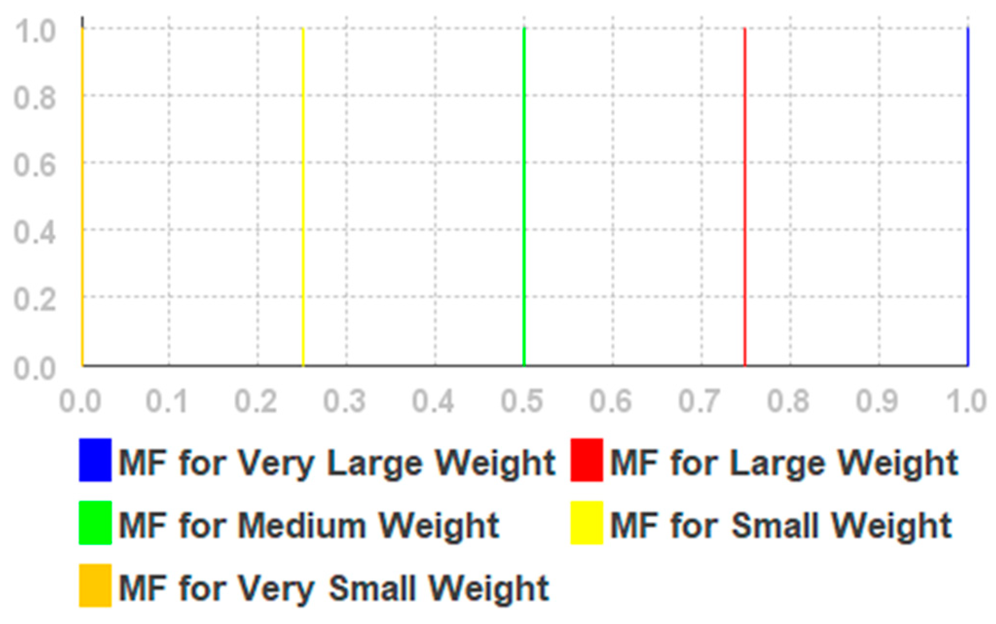
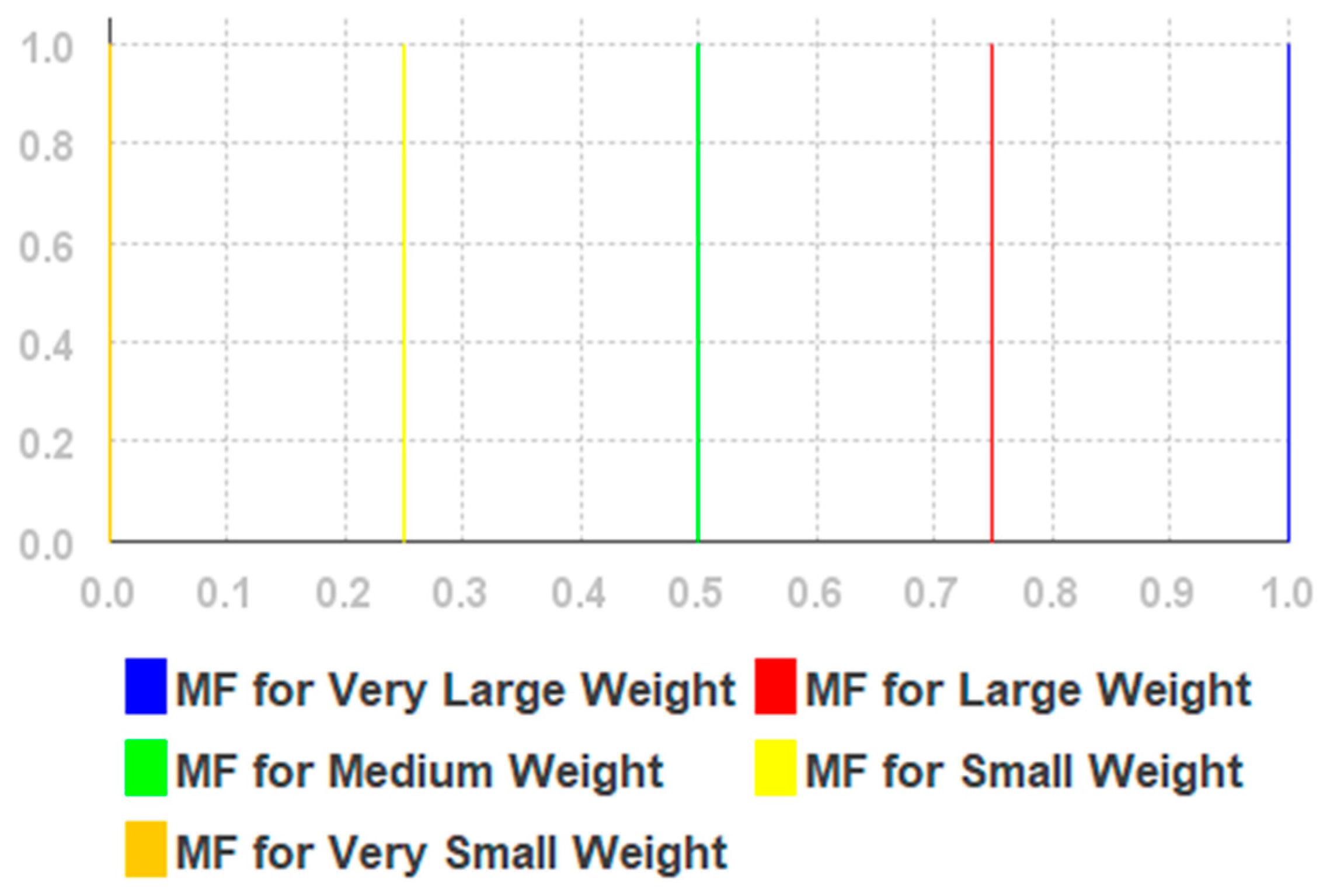
| Linguistic Variables | Membership Function Variable Values |
|---|---|
| Very Small Weight | 0.0 |
| Small Weight | 2.5 |
| Medium Weight | 5.0 |
| Large Weight | 7.5 |
| Very Large Weight | 10.0 |
| Linguistic Variables | Membership Function Variable Values |
|---|---|
| Very Small Distance | 0.0→0.0→2.5 |
| Small Distance | 0.0→2.5→5.0 |
| Medium Distance | 2.5→5.0→7.5 |
| Large Distance | 5.0→7.5→10.0 |
| Very Large Distance | 7.5→10.0→10.0 |
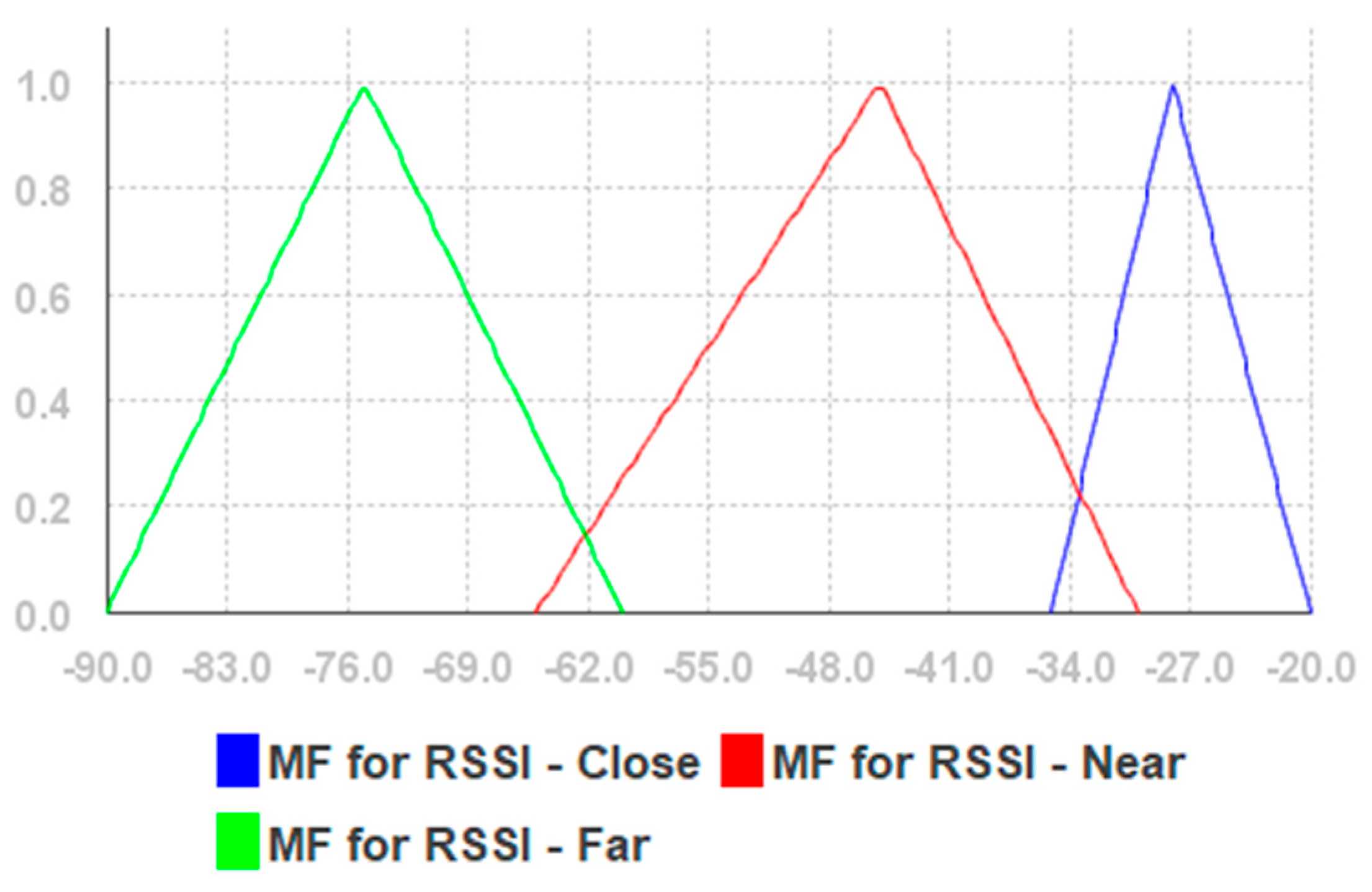
| Linguistic Variables | Membership Function Variable Values |
|---|---|
| RSSI-Close | −35.0→−28.0→−20.0 |
| RSSI-Near | −66.0→−44.5→−31.0 |
| RSSI-Far | −90.0→−75.0→−60.5 |
| Linguistic Variables | Membership Function Variable Values |
|---|---|
| Very Small Weight | 0.0 |
| Small Weight | 2.5 |
| Medium Weight | 5.0 |
| Large Weight | 7.5 |
| Very Large Weight | 10.0 |
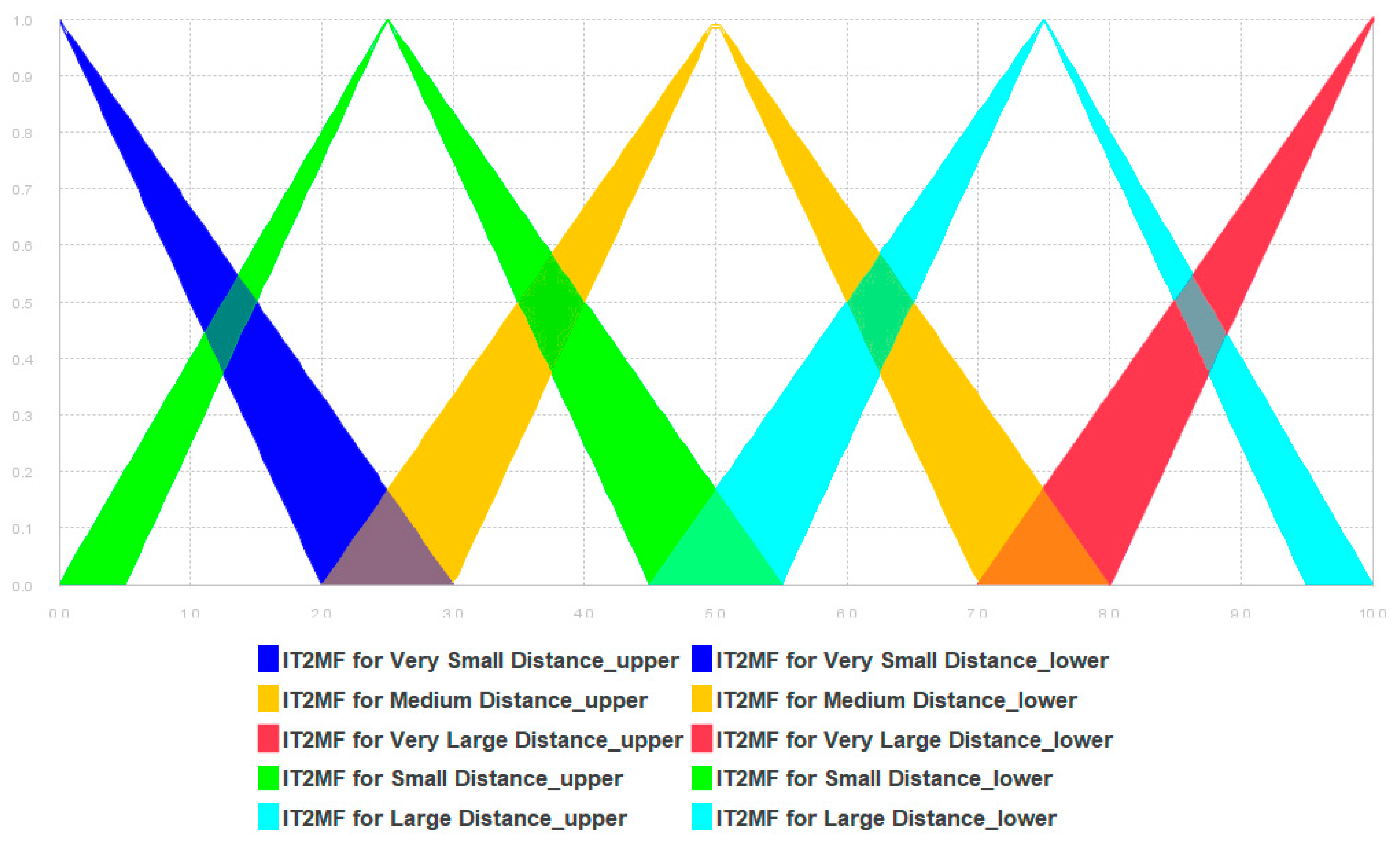
| Linguistic Variables | Upper Membership Function | Lower Membership Function |
|---|---|---|
| Very Small Distance | 0.0→0.0→3.0 | 0.0→0.0→2.0 |
| Small Distance | 0.0→2.5→5.5 | 0.5→2.5→4.5 |
| Medium Distance | 2.0→5.0→8.0 | 3.0→5.0→7.0 |
| Large Distance | 4.5→7.5→10.0 | 5.5→7.5→9.5 |
| Very Large Distance | 7.0→10.0→10.0 | 8.0→10.0→10.0 |
References
- Wise, E.; Li, B.; Gallagher, T.; Dempster, A.G.; Rizos, C.; Ramsey-Stewart, E.; Woo, D. Indoor navigation for people who are blind or vision impaired: Where are we and where are we going? J. Locat. Based Serv. 2014, 8, 54–73. [Google Scholar] [CrossRef]
- Legge, G.E.; Beckmann, P.J.; Tjan, B.S.; Havey, G.; Kramer, K.; Rolkosky, D.; Gage, R.; Chen, M.; Puchakayala, S.; Rangarajan, A. Indoor Navigation by People with Visual Impairment Using a Digital Sign System. PLoS ONE 2013, 8, e76783. [Google Scholar] [CrossRef]
- Van Haute, T.; De Poorter, E.; Crombez, P.; Lemic, F.; Handziski, V.; Wirström, N.; Wolisz, A.; Voigt, T.; Moerman, I. Performance analysis of multiple Indoor Positioning Systems in a healthcare environment. Int. J. Health Geogr. 2016, 15, 7. [Google Scholar] [CrossRef] [PubMed]
- Kanwal, N.; Bostanci, E.; Currie, K.; Clark, A.F. A Navigation System for the Visually Impaired: A Fusion of Vision and Depth Sensor. Appl. Bionics Biomech. 2015, 2015, 479857. [Google Scholar] [CrossRef]
- Xiao, A.; Chen, R.; Li, D.; Chen, Y.; Wu, D. An indoor positioning system based on static objects in large indoor scenes by using smartphone cameras. Sensors 2018, 18, 2229. [Google Scholar] [CrossRef] [PubMed]
- Fusco, G.; Coughlan, J.M. Indoor Localization Using Computer Vision and Visual-Inertial Odometry. In Computers Helping People with Special Needs. ICCHP 2018. Lecture Notes in Computer Science 2018; Miesenberger, K., Kouroupetroglou, G., Eds.; Springer: Cham, Switzerland, 2018; Volume 10897, pp. 86–93. [Google Scholar]
- Bramhe, M.V.; Gan, J.; Ghodpage, N.; Nawale, A.; Bahe, G. Indoor Positioning System using Magnetic Positioning and BLE beacons. Int. Res. J. Eng. Technol. 2017, 4, 1031–1036. [Google Scholar]
- Ando, B.; Baglio, S.; Marletta, V.; Crispino, R.; Pistorio, A. A measurement strategy to assess the optimal design of an RFID-based navigation aid. IEEE Trans. Instrum. Meas. 2018. [Google Scholar] [CrossRef]
- Du, H.; Zhang, C.; Ye, Q.; Xu, W.; Kibenge, P.L.; Yao, K. A hybrid outdoor localization scheme with high-position accuracy and low-power consumption. EURASIP J. Wirel. Commun. Netw. 2018, 2018. [Google Scholar] [CrossRef]
- Huh, J.; Seo, K. An indoor location-based control system using Bluetooth beacons for IoT systems. Sensors 2017, 17, 2917. [Google Scholar] [CrossRef]
- Kawai, T.; Matsui, K.; Honda, Y.; Villarubia, G.; Rodriguez, J.M.C. Preliminary study for improving accuracy on Indoor positioning method using compass and walking detect. In 14th International Conference on Distributed Computing and Artificial Intelligence, DCAI 2017. Advances in Intelligent Systems and Computing 2018; Springer: Cham, Switzerland, 2018; Volume 620, pp. 318–325. [Google Scholar] [CrossRef]
- Lee, H.S.; Lee, S.H.; Lee, J.G.; Lee, J.K. Design of Beacon-Based Positioning System Using RF and Sound Wave in Smartphone. In Advances in Computer Science and Ubiquitous Computing. CUTE 2017, CSA 2017. Lecture Notes in Electrical Engineering 2018; Park, J., Loia, V., Yi, G., Sung, Y., Eds.; Springer: Singapore, 2017; Volume 474. [Google Scholar]
- Naz, A.; Asif, H.M.; Umer, T.; Kim, B. PDOA based indoor positioning using visible light communication. IEEE Access 2018, 6, 7557–7564. [Google Scholar] [CrossRef]
- Uradzinski, M.; Guo, H.; Liu, X.; Yu, M. Advanced indoor positioning using zigbee wireless technology. Wirel. Person. Commun. 2017, 97, 6509–6518. [Google Scholar] [CrossRef]
- Ruggiero, L.; Charitha, D.; Xiang, S.; Lucia, B. Investigating pedestrian navigation in indoor open space environments using big data. Appl. Math. Model. 2018, 62, 499–509. [Google Scholar] [CrossRef]
- Liu, W.; Jiang, H.; Jiang, G.; Liu, J.; Ma, X.; Jia, Y.; Xiao, F. Indoor Navigation with Virtual Graph Representation: Exploiting Peak Intensities of Unmodulated Luminaries. IEEE/ACM Trans. Netw. 2019, 27, 187–200. [Google Scholar] [CrossRef]
- Segura, M.; Mut, V.; Sisterna, C. Ultra wideband indoor navigation system. IET Radar Sonar Navig. 2012, 6, 402. [Google Scholar] [CrossRef]
- Großwindhager, B.; Rath, M.; Kulmer, J.; Bakr, M.S.; Boano, C.A.; Witrisal, K.; Römer, K. SALMA: UWB-based Single-Anchor Localization System Using Multipath Assistance. In Proceedings of the 16th ACM Conference on Embedded Networked Sensor Systems, SenSys’18, Shenzhen, China, 4–7 November 2018; pp. 132–144. [Google Scholar] [CrossRef]
- Zhang, K.; Shen, C.; Zhou, Q.; Wang, H.; Gao, Q.; Chen, Y. A combined GPS UWB and MARG locationing algorithm for indoor and outdoor mixed scenario. Clust. Comput. 2018, 1–10. [Google Scholar] [CrossRef]
- Zhou, Y.; Zheng, X.; Chen, R.; Xiong, H.; Guo, S. Image-Based Localization Aided Indoor Pedestrian Trajectory Estimation Using Smartphones. Sensors 2018, 18, 258. [Google Scholar] [CrossRef]
- Sun, Y.; Zhao, Y.; Schiller, J. An indoor positioning system based on inertial sensors in smartphone. In Proceedings of the 2015 IEEE Wireless Communications and Networking Conference (WCNC), New Orleans, LA, USA, 9–12 March 2015; pp. 2221–2226. [Google Scholar] [CrossRef]
- Qiu, S.; Wang, Z.; Zhao, H.; Qin, K.; Li, Z.; Hu, H. Inertial/magnetic sensors based pedestrian dead reckoning by means of multi-sensor fusion. Inf. Fusion 2018, 39, 108–119. [Google Scholar] [CrossRef]
- Zhao, H.; Wang, Z.; Qiu, S.; Shen, Y.; Zhang, L.; Tang, K.; Fortino, G. Heading Drift Reduction for Foot-Mounted Inertial Navigation System via Multi-Sensor Fusion and Dual-Gait Analysis. IEEE Sens. J. 2018, 18, 1. [Google Scholar] [CrossRef]
- Yang, B.; Xu, X.; Zhang, T.; Li, Y.; Tong, J. An Indoor Navigation System Based on Stereo Camera and Inertial Sensors with Points and Lines. J. Sens. 2018, 2018, 4801584. [Google Scholar] [CrossRef]
- Meliones, A.; Sampson, D. Blind MuseumTourer: A System for Self-Guided Tours in Museums and Blind Indoor Navigation. Technologies 2018, 6, 4. [Google Scholar] [CrossRef]
- Rezazadeh, J.; Subramanian, R.; Sandrasegaran, K.; Kong, X.; Moradi, M.; Khodamoradi, F. Novel iBeacon placement for indoor positioning in IoT. IEEE Sens. J. 2018, 18, 10240–10247. [Google Scholar] [CrossRef]
- Wang, J.; Hu, A.; Liu, C.; Li, X. A Floor-Map-Aided WiFi/Pseudo-Odometry Integration Algorithm for an Indoor Positioning System. Sensors 2015, 15, 7096–7124. [Google Scholar] [CrossRef] [PubMed] [Green Version]
- Nguyen-Huu, K.; Lee, K.; Lee, S.-W. An indoor positioning system using pedestrian dead reckoning with WiFi and map-matching aided. In Proceedings of the 2017 International Conference on Indoor Positioning and Indoor Navigation (IPIN), Sapporo, Japan, 18–21 September 2017; pp. 1–8. [Google Scholar] [CrossRef]
- Xu, W.; Liu, L.; Zlatanova, S.; Penard, W.; Xiong, Q. A pedestrian tracking algorithm using grid-based indoor model. Autom. Constr. 2018, 92, 173–187. [Google Scholar] [CrossRef]
- Patel, M.; Girgensohn, A.; Biehl, J. Fusing Map Information with a Probabilistic Sensor Model for Indoor Localization Using RF Beacons. In Proceedings of the 2018 International Conference on Indoor Positioning and Indoor Navigation (IPIN), Nantes, France, 24–27 September 2018; pp. 1–8. [Google Scholar] [CrossRef]
- Jeong, J.P.; Yeon, S.; Kim, T.; Lee, H.; Kim, S.M.; Kim, S. SALA: Smartphone-assisted localization algorithm for positioning indoor IoT devices. Wirel. Netw. 2018, 24, 27–47. [Google Scholar] [CrossRef]
- Link, J.A.B.; Smith, P.; Viol, N.; Wehrle, K. Footpath: Accurate map-based indoor navigation using smartphones. In Proceedings of the 2011 International Conference on Indoor Positioning and Indoor Navigation (IPIN), Guimaraes, Portugal, 21–23 September 2011; pp. 1–8. [Google Scholar]
- Tomazic, S.; Dovzan, D.; Skrjanc, I. Confidence-Interval-Fuzzy-Model-Based Indoor Localization. IEEE Trans. Ind. Electron. 2019, 66, 2015–2024. [Google Scholar] [CrossRef]
- Dari, Y.E.; Suyoto, S.; Pranowo, P. CAPTURE: A mobile based indoor positioning system using wireless indoor positioning system. Int. J. Interact. Mobile Technol. 2018, 12, 61–72. [Google Scholar] [CrossRef]
- Cong, C.; Men, X. An Innovative Indoor Location Algorithm Based on Supervised Learning and WIFI Fingerprint Classification. In Signal and Information Processing, Networking and Computers, ICSINC 2017; Springer: Singapore, 2018; pp. 238–246. [Google Scholar]
- Raspopoulos, M. Multidevice map-constrained fingerprint-based indoor positioning using 3-D ray tracing. IEEE Trans. Instrum. Meas. 2018, 67, 466–476. [Google Scholar] [CrossRef]
- Song, Q.; Guo, S.; Liu, X.; Yang, Y. CSI amplitude fingerprinting based NB-IoT indoor localization. IEEE Internet Things J. 2017. [Google Scholar] [CrossRef]
- Subedi, S.; Pyun, J.-Y. Practical Fingerprinting Localization for Indoor Positioning System by Using Beacons. J. Sens. 2017, 2017, 9742170. [Google Scholar] [CrossRef]
- Wang, Y.; Wu, X.; Cheng, L. A Novel Non-Line-of-Sight Indoor Localization Method for Wireless Sensor Networks. J. Sens. 2018, 2018, 3715372. [Google Scholar] [CrossRef]
- Li, B.; Munoz, J.P.; Rong, X.; Chen, Q.; Xiao, J.; Tian, Y.; Yousuf, M. Vision-Based Mobile Indoor Assistive Navigation Aid for Blind People. IEEE Trans. Mobile Comput. 2019, 18, 702–714. [Google Scholar] [CrossRef] [PubMed]
- Deng, Z.; Fu, X.; Wang, H. An IMU-aided body-shadowing error compensation method for indoor bluetooth positioning. Sensors 2018, 18, 304. [Google Scholar] [CrossRef]
- Al-Qudsi, B.; Joram, N.; El-Shennawy, M.; Ellinger, F. Scalable indoor positioning system with multi-band FMCW. IET Radar Sonar Navig. 2018, 12, 46–55. [Google Scholar] [CrossRef]
- Seco, F.; Jiménez, A.R. Smartphone-based cooperative indoor localization with RFID technology. Sensors 2018, 18, 266. [Google Scholar] [CrossRef]
- Klepal, M.; Beauregard, S. A novel backtracking particle filter for pattern matching indoor localization. In Proceedings of the First ACM International Workshop on Mobile Entity Localization and Tracking in GPS-Less Environments, San Francisco, CA, USA, 19 September 2008; pp. 79–83. [Google Scholar]
- Dierna, G.L.; Machì, A.; Scirè, S. A ROS Driven Platform for Radiomap Management Optimization in Fingerprinting Based Indoor Positioning. In Intelligent Interactive Multimedia Systems and Services 2017; KES-IIMSS-18; Springer: Cham, Switzerland, 2018; Volume 76, pp. 139–150. [Google Scholar] [CrossRef]
- Fu, Y.; Chen, P.; Yang, S.; Tang, J. An indoor localization algorithm based on continuous feature scaling and outlier deleting. IEEE Internet Things J. 2018, 5, 1108–1115. [Google Scholar] [CrossRef]
- Geng, X.; Zhou, M.; Wei, Y.; Tang, Y. Indoor WLAN Collaborative Localization Algorithm Based on Geometric Figure Overlap. In Communications, Signal Processing, and Systems. CSPS 2016. Lecture Notes in Electrical Engineering; Liang, Q., Mu, J., Wang, W., Zhang, B., Eds.; Springer: Singapore, 2016; Volume 423, pp. 515–524. [Google Scholar]
- Krasuski, A.; Meina, M. Correcting Inertial Dead Reckoning Location Using Collision Avoidance Velocity-Based Map Matching. Appl. Sci. 2018, 8, 1830. [Google Scholar] [CrossRef]
- Du, X.; Wu, J.; Yang, K.; Wang, L. An AP-Centred Indoor Positioning System Combining Fingerprint Technique. In Proceedings of the 2016 IEEE Global Communications Conference (GLOBECOM), Washington, DC, USA, 4–8 December 2016; pp. 1–6. [Google Scholar] [CrossRef]
- Machaj, J.; Brida, P. Impact of optimization algorithms on hybrid indoor positioning based on GSM and wi-fi signals. Concurr. Comput. 2017, 29, e3911. [Google Scholar] [CrossRef]
- Guo, H.; Li, H.; Xiong, J.; Yu, M. Indoor positioning system based on particle swarm optimization algorithm. Measurement 2019, 134, 908–913. [Google Scholar] [CrossRef]
- Brena, R.F.; García-Vázquez, J.P.; Galván-Tejada, C.E.; Muñoz-Rodriguez, D.; Vargas-Rosales, C.; Fangmeyer, J. Evolution of Indoor Positioning Technologies: A Survey. J. Sens. 2017, 2017, 2630413. [Google Scholar] [CrossRef]
- Chow, J.C.K.; Peter, M.; Scaioni, M.; Al-Durgham, M. Indoor Tracking, Mapping, and Navigation: Algorithms, Technologies, and Applications. J. Sens. 2018, 2018, 5971752. [Google Scholar] [CrossRef]
- Davidson, P.; Piché, R. A survey of selected indoor positioning methods for smartphones. IEEE Commun. Surv. Tutor. 2017, 19, 1347–1370. [Google Scholar] [CrossRef]
- Orujov, F.; Maskeliūnas, R.; Damaševičius, R.; Wei, W.; Li, Y. Smartphone based intelligent indoor positioning using fuzzy logic. Future Gener. Comput. Syst. 2018, 89, 335–348. [Google Scholar] [CrossRef]
- Zadeh, L.A. Fuzzy algorithms. Inf. Control 1968, 12, 94–102. [Google Scholar] [CrossRef] [Green Version]
- Jiang, L. A WLAN Fingerprinting Based Indoor Localization Technique. MSc Thesis, University of Nebraska-Lincoln, Lincoln, NE, USA, 2012; p. 38. [Google Scholar]
- Turgut, Z.; Üstebay, S.; Aydın, G.Z.G.; Sertbaş, A. Deep Learning in Indoor Localization Using WiFi. In International Telecommunications Conference. Lecture Notes in Electrical Engineering 2019; Boyaci, A., Ekti, A., Aydin, M., Yarkan, S., Eds.; Springer: Singapore, 2019; Volume 504, pp. 101–110. [Google Scholar]
- Chi, W.; Tian, Y.; Al-Rodhaan, M.; Al-Dhelaan, A.; Jin, Y. A Revised Received Signal Strength Based Localization for Healthcare. Int. J. Multimedia Ubiquitous Eng. 2015, 10, 273–282. [Google Scholar] [CrossRef]
- Sebastian, S.; Ramakrishnan, T.V. Multi-fuzzy sets: An extension of fuzzy sets. Fuzzy Inf. Eng. 2011, 3, 35. [Google Scholar] [CrossRef]
- Harliana, P.; Rahim, R. Comparative Analysis of Membership Function on Mamdani Fuzzy Inference System for Decision Making. J. Phys. 2017, 930, 12029. [Google Scholar] [CrossRef]
- Faragher, R.; Harle, R. An Analysis of the Accuracy of Bluetooth Low Energy for Indoor Positioning Applications. J. Netw. Sci. 2015, 4, 22–26. [Google Scholar]
- Rodríguez, R.M.; Martínez, L.; Torra, V.; Xu, Z.S.; Herrera, F. Hesitant Fuzzy Sets: State of the Art and Future Directions. Int. J. Intell. Syst. 2014, 29, 495–524. [Google Scholar] [CrossRef] [Green Version]
- Har-Peled, S.; Raichel, B. The Fréchet distance revisited and extended. ACM Trans. Algorithms 2014, 10, 3. [Google Scholar] [CrossRef]
- Gastaldo, P.; Zunino, R. Hausdorff distance for target detection. IEEE Int. Symp. Circuits Syst. 2002, 5, 661–664. [Google Scholar]
- Torres-Sospedra, J.; Jiménez, A.R.; Knauth, S.; Moreira, A.; Beer, Y.; Fetzer, T.; Ta, V.-C.; Montoliu, R.; Seco, F.; Mendoza-Silva, G.M.; et al. The Smartphone-Based Offline Indoor Location Competition at IPIN 2016: Analysis and Future Work. Sensors 2017, 17, 557. [Google Scholar] [CrossRef]
- Ganz, A.; Schafer, J.; Gandhi, S.; Puleo, E.; Wilson, C.; Robertson, M. PERCEPT Indoor Navigation System for the Blind and Visually Impaired: Architecture and Experimentation. Int. J. Telemed. Appl. 2012, 2012, 894869. [Google Scholar] [CrossRef]
- Bulusu, N.; Heidemann, J.; Estrin, D. Adaptive beacon placement. In Proceedings of the 21st International Conference on Distributed Computing Systems, Mesa, AZ, USA, 16–19 April 2001; pp. 489–498. [Google Scholar] [CrossRef]
- Küpper, A. Location-Based Services: Fundamentals and Operation; Wiley: Hoboken, NJ, USA, 2005; p. 365. [Google Scholar]
- Kolodziej, K.W.; Hjelm, J. Local Positioning Systems: LBS Applications and Services; CRC Press: Boca Raton, FL, USA, 2006; p. 445. [Google Scholar]
- Liang, S.C.; Liao, L.H.; Lee, Y.C. Localization algorithm based on improved weighted centroid in wireless sensor networks. J. Netw. 2014, 9, 183–189. [Google Scholar] [CrossRef]
- Dong, Q.; Xu, X. A novel weighted centroid localization algorithm based on rssi for an outdoor environment. J. Commun. 2014, 9, 279–285. [Google Scholar] [CrossRef]
- Shchekotov, M. Indoor localization method based on Wi-Fi trilateration technique. In Proceedings of the 16th Conference of Open Innovations Association FRUCT, Oulu, Finland, 27–31 October 2014; pp. 177–179. [Google Scholar]
- Lymberopoulos, D.; Liu, J. The Microsoft Indoor Localization Competition: Experiences and Lessons Learned. IEEE Signal Process. Mag. 2017, 34, 125–140. [Google Scholar] [CrossRef]
- Sung, K.; Lee, D.K.; Kim, H. Indoor Pedestrian Localization Using iBeacon and Improved Kalman Filter. Sensors 2018, 18, 1722. [Google Scholar] [CrossRef]
- Chen, G.; Meng, X.; Wang, Y.; Zhang, Y.; Tian, P.; Yang, H. Integrated WiFi/PDR/Smartphone Using an Unscented Kalman Filter Algorithm for 3D Indoor Localization. Sensors 2015, 15, 24595–24614. [Google Scholar] [CrossRef] [Green Version]
- Lee, S.; Kim, J.; Moon, N. Random forest and WiFi fingerprint-based indoor location recognition system using smart watch. Hum.-Centric Comput. Inf. Sci. 2019, 9, 6. [Google Scholar] [CrossRef]
- Kanaris, L.; Kokkinis, A.; Liotta, A.; Stavrou, S. Fusing Bluetooth Beacon Data with Wi-Fi Radiomaps for Improved Indoor Localization. Sensors 2017, 17, 812. [Google Scholar] [CrossRef]
- Chen, J.; Zhang, Y.; Xue, W. Unsupervised Indoor Localization Based on Smartphone Sensors, iBeacon and Wi-Fi. Sensors 2018, 18, 1378. [Google Scholar] [CrossRef]
- Bi, J.; Wang, Y.; Li, X.; Qi, H.; Cao, H.; Xu, S. An Adaptive Weighted KNN Positioning Method Based on Omnidirectional Fingerprint Database and Twice Affinity Propagation Clustering. Sensors 2018, 18, 2502. [Google Scholar] [CrossRef] [PubMed]
| Method | Technology | Environment | Error in Meters | Error % |
|---|---|---|---|---|
| Segura et al. [17] | UWB | Room (6 m × 8 m) | 0.2 | N/A |
| Zhang et al. [19] | GPS, UWB, MARG | Business center | 3.2 | N/A |
| Sun et al. [21] | PDR | Atrium of Informatics Forum building (9.7 m × 5.94 m) | 1.96 | N/A |
| Yang et al. [24] | Stereo Camera | Room (8 m × 8.4 m × 4 m) | 0.677 | N/A |
| Qiu et al. [22] | Inertial/magnetic sensors, PDR | Room (approx. 20 m diameter, height 10 m), empty room | 2.59 | N/A |
| Meliones et al. [25] | Inertial dead-reckoning, BLE beacon | Floor (1640 m2) | N/A | 2.53% |
| Liu et al. [16] | Peak intensities of lights | Supermarket (1000 m2) | N/A | 0% |
| Shopping mall (20 000 m2) | N/A | 1.7% | ||
| Office building (800 m2) | N/A | 0% | ||
| Großwindhager et al. [18] | UWB | Office room (4 m × 6 m) | 0.2 | N/A |
| Zhou et al. [20] | Camera, PDR | Meeting room (16 m × 7.7 m) | 0.56 | N/A |
| Xu et al. [29] | grid-based, WiFi | Office (780 m2) Lab (1200 m2) | 3.5m | N/A |
| Wang et al. [27] | WiFi, PDR | Floor in China University of Mining and Technology | 4.99 | N/A |
| Nguyen-Huu et al. [28] | PDR, WiFi fingerprint | Floor in Engineering building, Hallym University | 2.40 | N/A |
| Patel et al. [30] | BLE, Mapping/Poi | Office floor (1200 m2) | 1.6 | N/A |
| Proposed Method | BLE fingerprint, fuzzy logic | Floor (52.5m × 12.5 m) | 0.43 | N/A |
© 2019 by the authors. Licensee MDPI, Basel, Switzerland. This article is an open access article distributed under the terms and conditions of the Creative Commons Attribution (CC BY) license (http://creativecommons.org/licenses/by/4.0/).
Share and Cite
AL-Madani, B.; Orujov, F.; Maskeliūnas, R.; Damaševičius, R.; Venčkauskas, A. Fuzzy Logic Type-2 Based Wireless Indoor Localization System for Navigation of Visually Impaired People in Buildings. Sensors 2019, 19, 2114. https://doi.org/10.3390/s19092114
AL-Madani B, Orujov F, Maskeliūnas R, Damaševičius R, Venčkauskas A. Fuzzy Logic Type-2 Based Wireless Indoor Localization System for Navigation of Visually Impaired People in Buildings. Sensors. 2019; 19(9):2114. https://doi.org/10.3390/s19092114
Chicago/Turabian StyleAL-Madani, Basem, Farid Orujov, Rytis Maskeliūnas, Robertas Damaševičius, and Algimantas Venčkauskas. 2019. "Fuzzy Logic Type-2 Based Wireless Indoor Localization System for Navigation of Visually Impaired People in Buildings" Sensors 19, no. 9: 2114. https://doi.org/10.3390/s19092114
APA StyleAL-Madani, B., Orujov, F., Maskeliūnas, R., Damaševičius, R., & Venčkauskas, A. (2019). Fuzzy Logic Type-2 Based Wireless Indoor Localization System for Navigation of Visually Impaired People in Buildings. Sensors, 19(9), 2114. https://doi.org/10.3390/s19092114