This subsection discusses the network architecture, propagation and energy model of BF-SPR-Three. Afterward, the neighbor’s selection procedure and tree establishment criteria are elaborated. Then the steps included in BF-SPR-Three are shown in Algorithm 2.
4.2.1. Network Configuration
Before explaining the network architecture of BF-SPR-Three, a few terms need to be defined here. The nodes which perform data forwarding including their own sensed data and the data they received from higher depth nodes, are known as relay nodes and the nodes which lie on the layer or coinciding with the layers are considered as cross nodes.
The proposed protocol BF-SPR-Three consists of sinks, relay nodes, cross nodes varying from (150–450) and surface gateways. Basically, the sink works as an embedded unit and housed with both acoustic and radio modems. The radio modem is used for the communication among sinks and base stations, while the acoustic modem is used for underwater communication and data collection among sinks and underwater sensor nodes (using multi-hop). Moreover, we assumed that:
Firstly, sinks have high energy. Moreover, they are connected with each other to balance the load of DPs on respective sinks.
Secondly, if the data is successfully delivered from any of the relay nodes to any of the sinks, then it means that data is successfully delivered to the control station.
In the end, we have not considered the movement of nodes in a vertical direction, which is almost negligible, whereas we have only considered the mobility of the nodes in the horizontal direction (due to water currents).
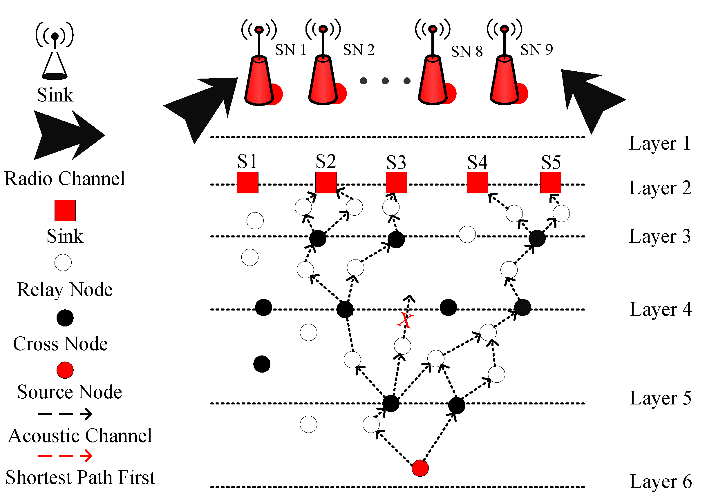
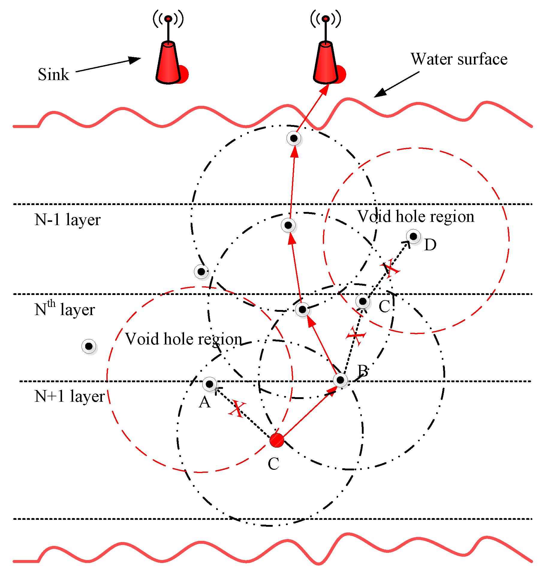
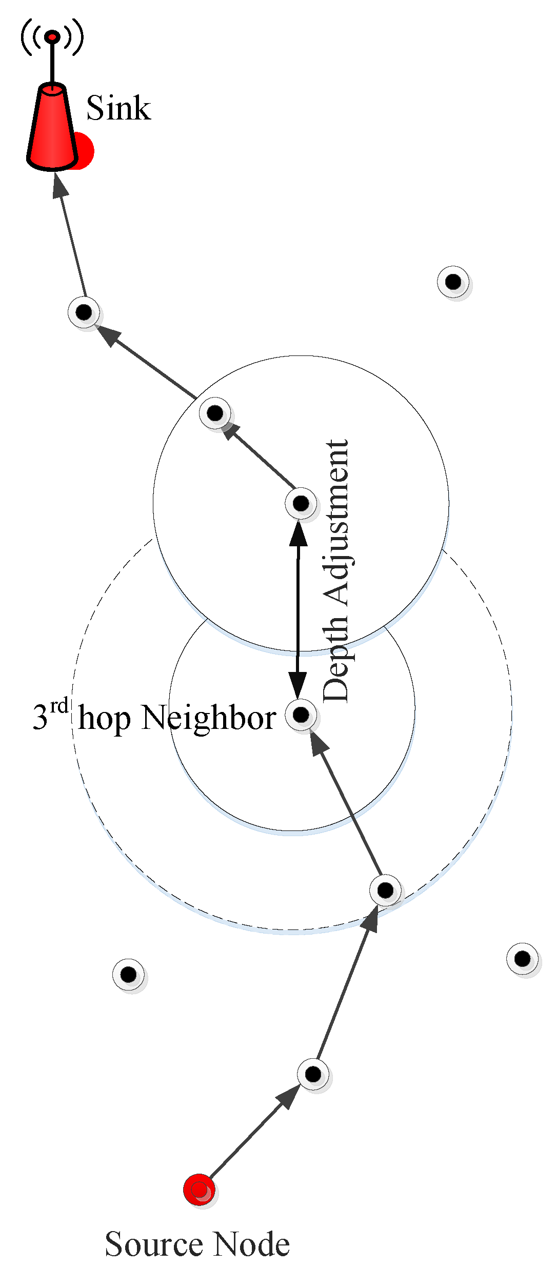
Initially, all the sensor nodes are randomly distributed in the underwater network and they are in sleeping mode (in this mode, nodes are basically alive, consuming a negligible amount of energy; however, they are not participating in the transmission process). When a node (during sleeping mode) receives a DP, then this node changes its status from sleeping to the active mode (in this mode, nodes actively participate in the transmission process and consume energy during packets reception and transmission). If any node is not participating in the transmission process, then that nodes get back to the sleeping mode again. In addition, the key step in the proposed protocol is binary tree generation. This tree generation procedure is adopted for multi-path transmission. Let us consider the LMPC routing protocol scenario (as shown in
Figure 8). In LMPC, the UWSN is distributed into layers. Moreover, the binary tree generation helps the routing protocol in reliable data delivery. Then, from every sensor node, different copies of DP are transmitted. This process remains continuous until the DP reaches the destined sink. While forwarding the DP from sea depth to lower depth, different noises including shipping noises add up with data and produce bit error in the packets. If this hindrance exceeds a certain limit, it ultimately drops the DP. Due to this reason, multiple copies of DP are required for reliable data delivery.
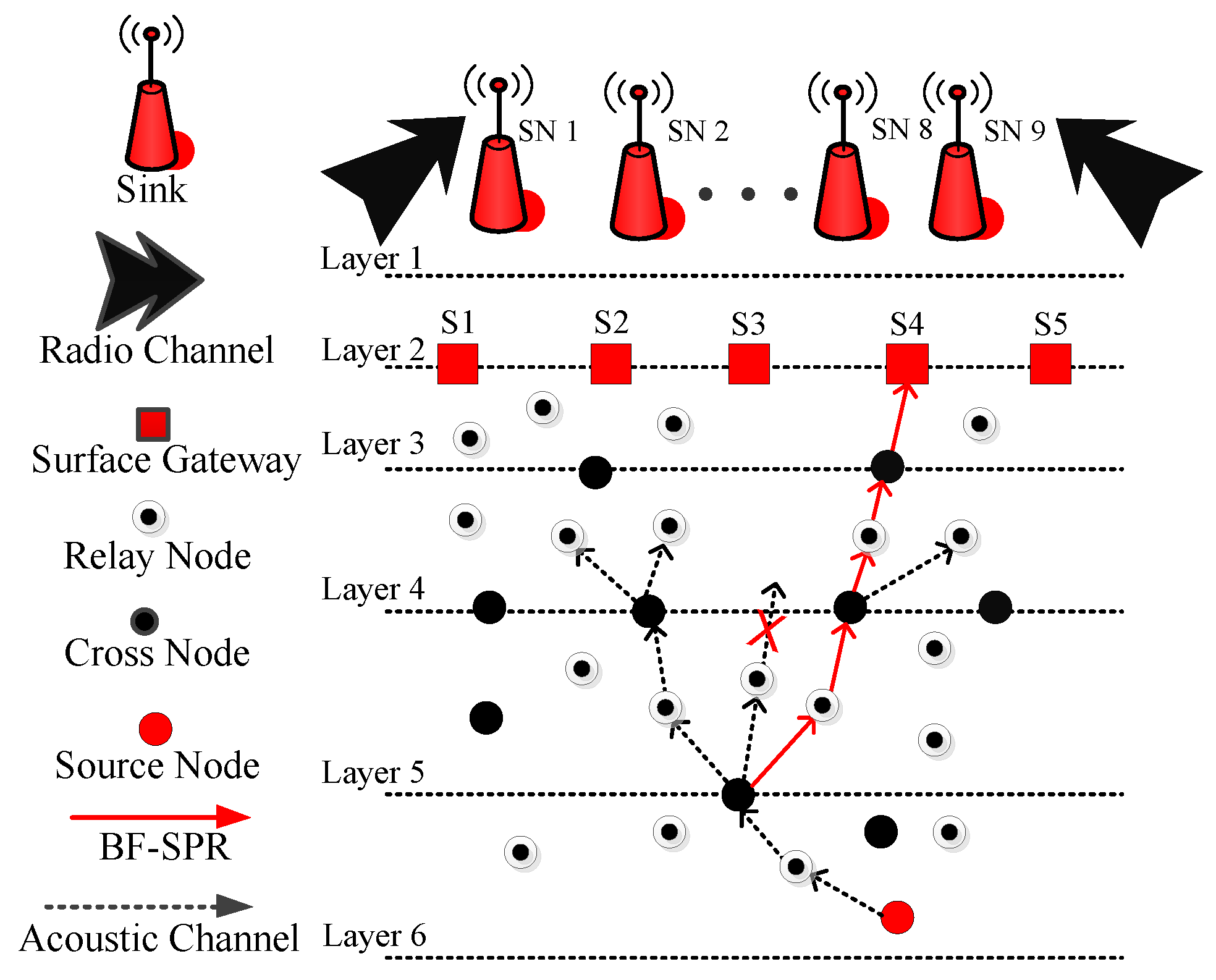
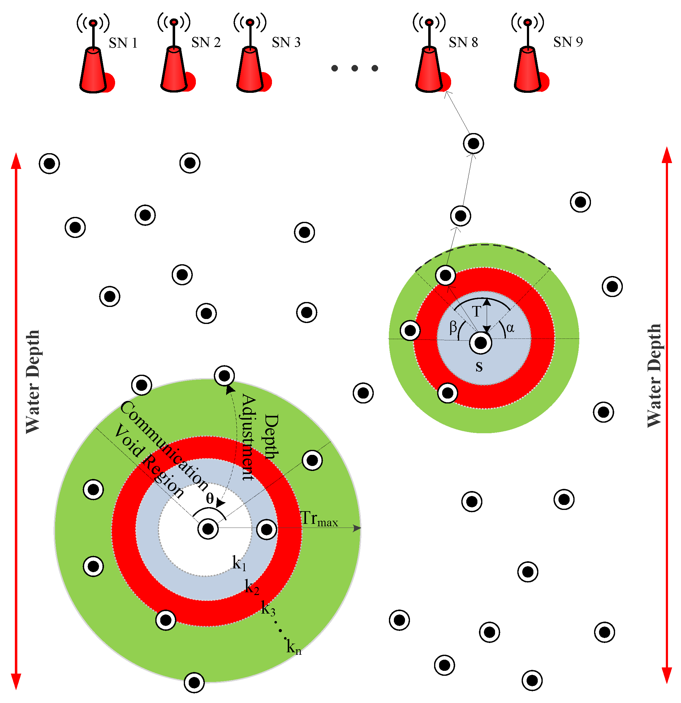
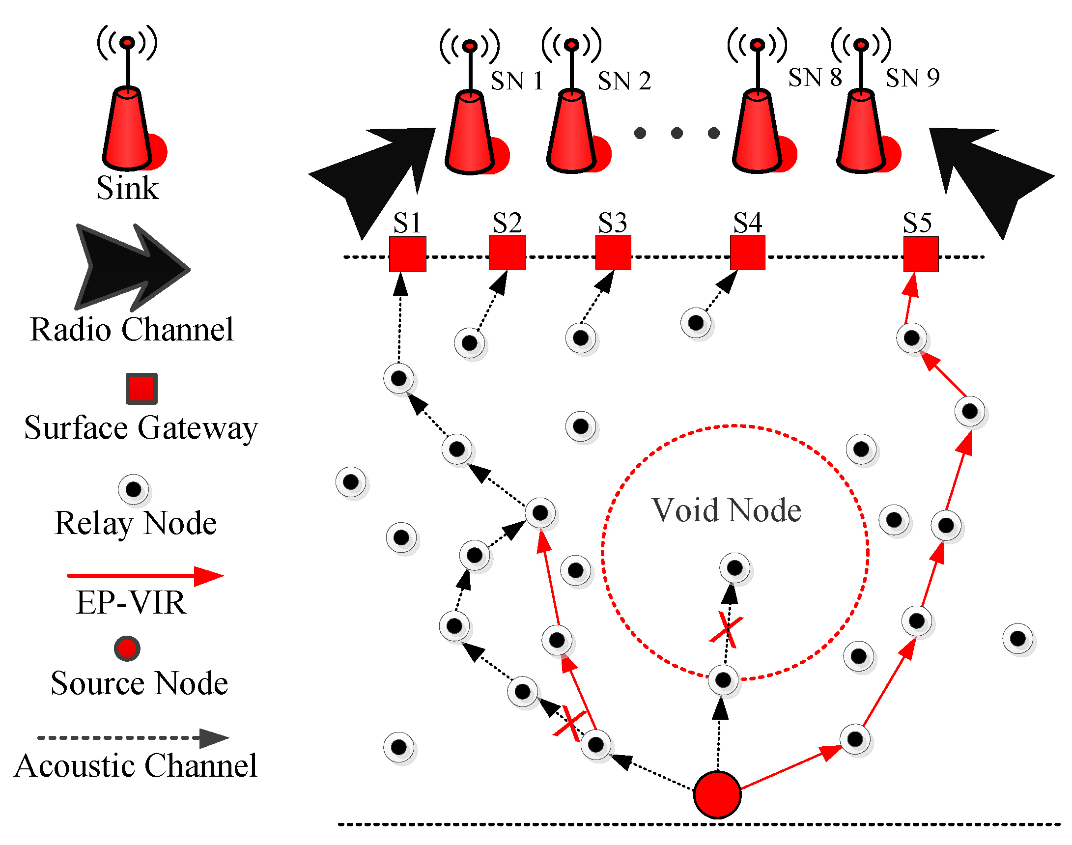
By keeping these parameters in mind, we have implemented a new routing protocol named BF-SPR-Three. The beacon mechanism is similar for EP-VIR-Three routing protocol. In BF-SPR-Three, the complete shortest and the efficient path is computed using the ‘BF’ algorithm. The network environment is distributed into unequal layers (closer near the sea surface and distanced at the sea bottom (see
Figure 10)). In the current protocol, the sensor node (source) generates a single copy of the data. As the data is advanced to the lower depth layer using relay nodes (selected from the BF algorithm), then the current forwarder (source node) checks the next forwarder node (destination node) regarding whether it is a cross-node or a simple relay node. Upon DPs reception, if the next forwarder node is a relay node, then it unicasts the DP. On the contrary, a cross-node uses IP multicasting technology (a bandwidth preserving technology that minimizes the traffic of DPs by instantaneously delivering a single stream of data to potentially thousands of corporate receivers) to transmit the DP. In current work, the IP of the neighbor nodes is their unique ID. In the end, these DPs are directed towards surface gateways and ultimately data reaches the sink. DPs are combined at the destined sink to generate the real DP and advanced towards control station.
Why ‘BF’ Algorithm?
In graph theory, negative weight edges can make negative weight cycles, i.e., a cycle which will diminish the path by returning to a similar point. Briefest path algorithms, i.e., ‘Dijkstra’ Algorithm, are not ready to distinguish such a cycle. Eventually, they give an unseemly outcome since they can experience a negative weight cycle and reduce the route length. Afterward, in this work, we chose to utilize a ‘BF’ algorithm for our proposed protocol.
Functioning of ‘BF’ Algorithm?
‘BF’ algorithm works by overestimating the length of the route from the earliest starting vertex to all unique vertices. By then, it iteratively slackens up those evaluations by finding new routes that are shorter than the as of late overestimated ways. By doing this on and on for all vertices, we can guarantee that the final route is upgraded. The essential steps of the ‘BF’ algorithm are:
Starts with a graph having weights,
Selects a starting node and allocates the infinity path value to all other nodes,
Visit each vertex and relax the path if it inaccurate,
Iterate these steps up to the number of nodes in the vertices,
After all the nodes have their path lengths, the algorithm will check for the negative cycles.
4.2.2. Detailed Theoretical Analysis of Propagation and Data Transmission Model
In this section, the propagation model and the EC model of the acoustic signals are explained. In addition, the absorption constraints are also formulated in the underwater environment. The propagation and EC model include:
Channel Fading Model in BF-SPR-Three
The attenuation of the acoustic channel is formulated using Equation (
2) as in [
24]:
where
k represents the spreading factor. Whereas,
denotes absorption coefficient. Basically, k is describing the propagation pattern. For cylindrical spreading,
k is taken as 1 with limited propagation pattern (with no attenuation). Similarly, for practical spreading, the value of
k is taken as 1.5. In this spreading, the signal propagation considers both transmission and attenuation losses to get the precise result. In the end,
k is taken as 2 for spherical spreading. In spherical spreading, the signal propagates in omni directions. However, these waves move a long way from source by keeping the power of the signal same. The
is defined by Thorp’s Model as in [
24].
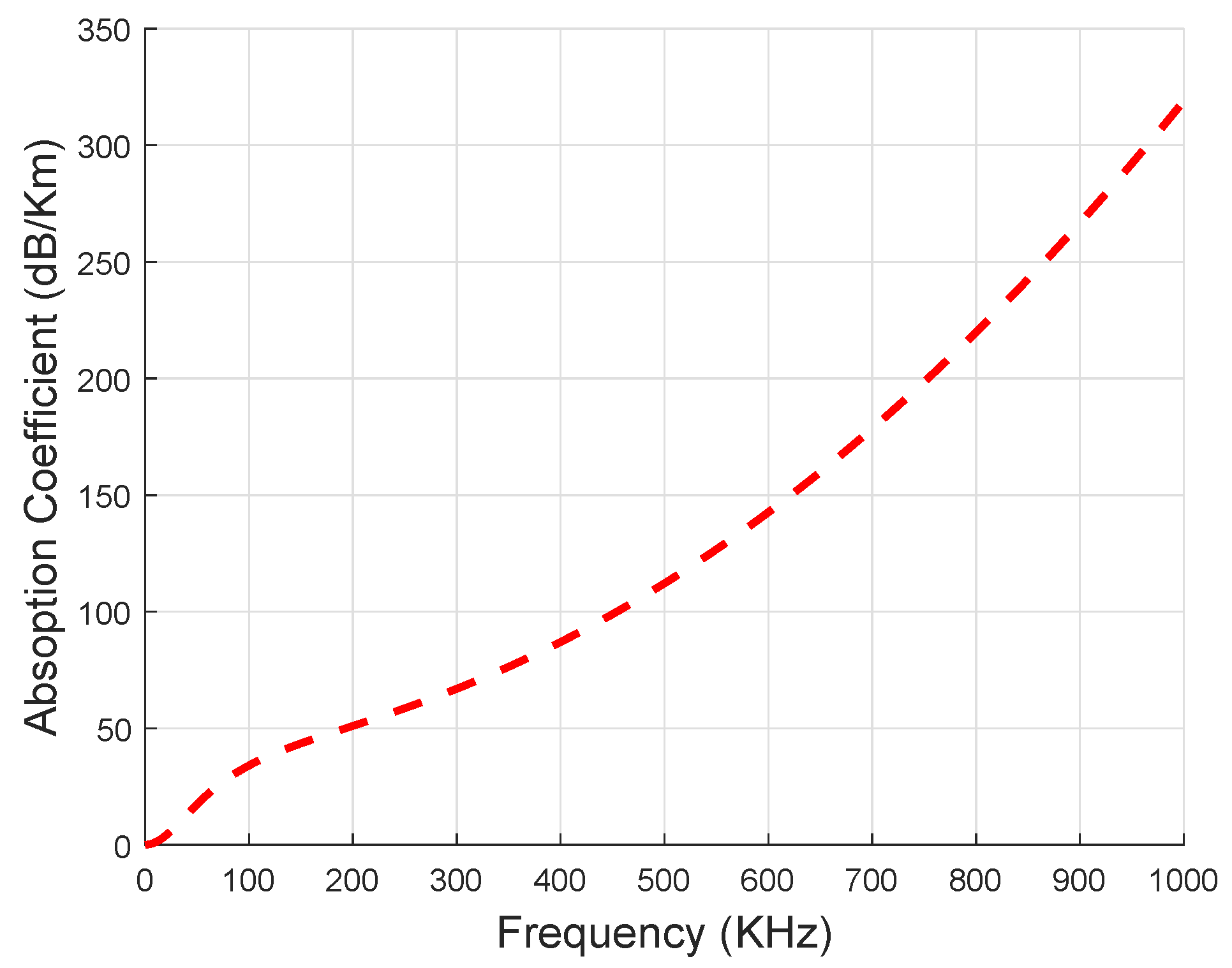
Here,
is measured in dB/Km and
f is measured in KHz, respectively. The relationship between
and
is shown in
Figure 11. From the figure, it is obvious that the absorption rate of the acoustic signal increases with the increase in
value. IoT-UWSN includes shipping noise, thermal noise and turbulence noise. Therefore, these noises affect the acoustic channel during transmission. The total Noise Power
including the spectral density of all the noises at frequency
is calculated as [
24]:
where, the aforemention total noises are represented by
. The value of
is measured in dB. The attenuation over the distance
is calculated using Equation (
5).
Here, is measured in dB and it should be lies in between (1-tn).
Channel Capacity Model in BF-SPR-Three
The Channel Capacity (cc) of the acoustic channel is formulated using Equations (
6) and (
7) as in [
24].
here,
B represents the bandwidth of the acoustic channel,
is used to denote signal to noise ratio (calculated using Equation (
8)). Meanwhile,
is used to represent the number of bits without any error and
is a binary entropy function using PER, which is defined as
.
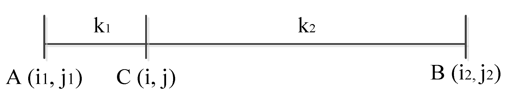
here,
P is the power of the acoustic signal and
is the distance among
and
nth nodes. Whereas, SNR follows the additive white gaussian noise channel.
Transmission and Receiving Energy Calculations in BF-SPR-Three
The EC of the sensor nodes during the packet transmission and reception is calculated using Equations (
9) and (
10).
Here, the EC of the sensor nodes during the packet transmission is denoted as
.
is used to represent the EC of the sensor nodes during the packet reception. Whereas,
and
denotes transmission and reception power of the sensor node, respectively. Packet size is represented as
and
is used to represent the data rate of the acoustic channel. The total residual energy of the nodes in the underwater environment after forwarding all the DP is denoted as
and computed using Equation (
11).
Here,
N represents the total number of
in the network. Where total hop counts (for a single
from source to the destination) are denoted as
. Whereas,
is used to represent ith node. The total residual energy of the nodes in the underwater environment after receiving all the
is denoted as
and computed using Equation (
12).
The initial energy of the node is represented as
. Whereas, the total energy of the network is denoted as
and calculated using Equation (
13).
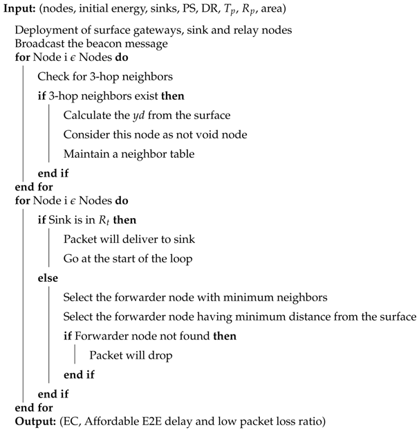
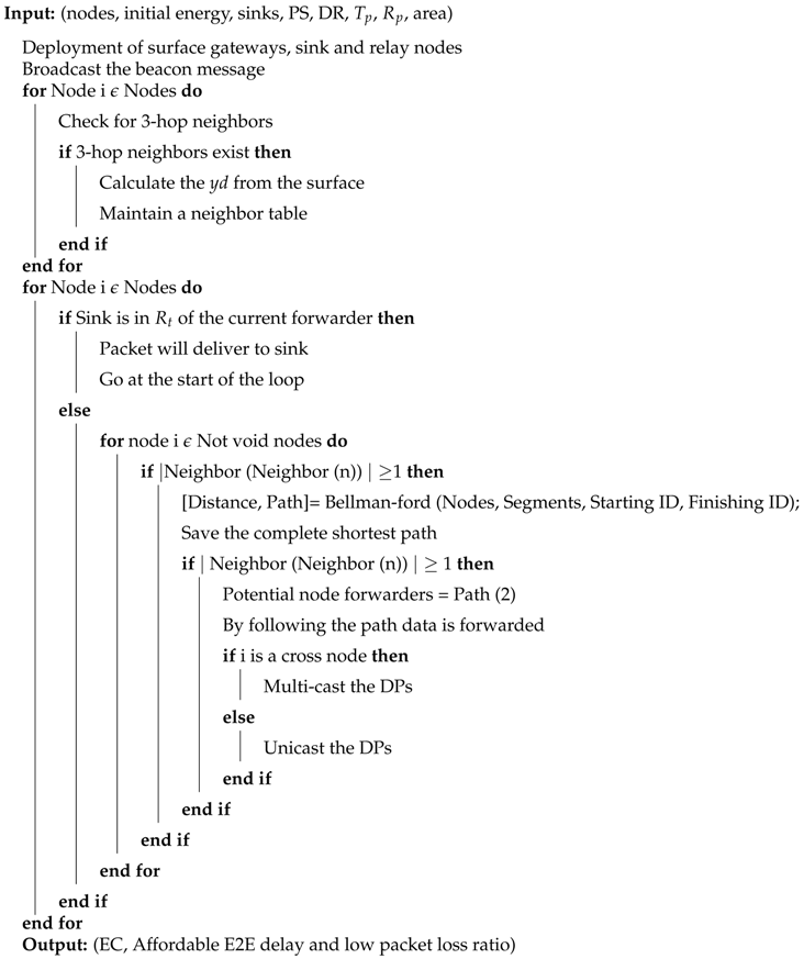
4.2.4. Description of Algorithm 2
In this subsection, the data forwarding algorithm for the proposed protocol (BF-SPR-Three) is discussed. The detail is given below.
| Algorithm 2 Algorithm of BF-SPR-Three for data forwarding |
![Sensors 19 01313 i002]() |
Firstly, the input parameters for the routing protocols are initialized. Then, the sensor, sink and relay nodes are deployed in the network with different surface gateways. Afterwards, a beacon message is broadcasted, which helps the neighbor nodes to update their routing table. Moreover, the protocol checks the 3-hop neighbor’s availability to avoid the void hole problem. In the end, transmission begins by selecting the next forwarder node given by the ‘BF’ algorithm (by providing the fastest and shortest path, to route the DP from the source node to the destined sink). Moreover, if the next forwarder is the simple sensor node, it will unicast the DP; otherwise, it will multicast the DP. In the end, if this forwarder node lies within the range of respective sink, then the data reaches the destined sink (using a binary tree generation approach); otherwise, the next forwarder node is selected (provided by the ‘BF’ algorithm).

 ,
, 


