Robust Construction Safety System (RCSS) for Collision Accidents Prevention on Construction Sites


Abstract
1. Introduction
2. Research Trend
2.1. Proximity Warning System
2.2. Summary of Previous Research
3. Research Objective and Scope
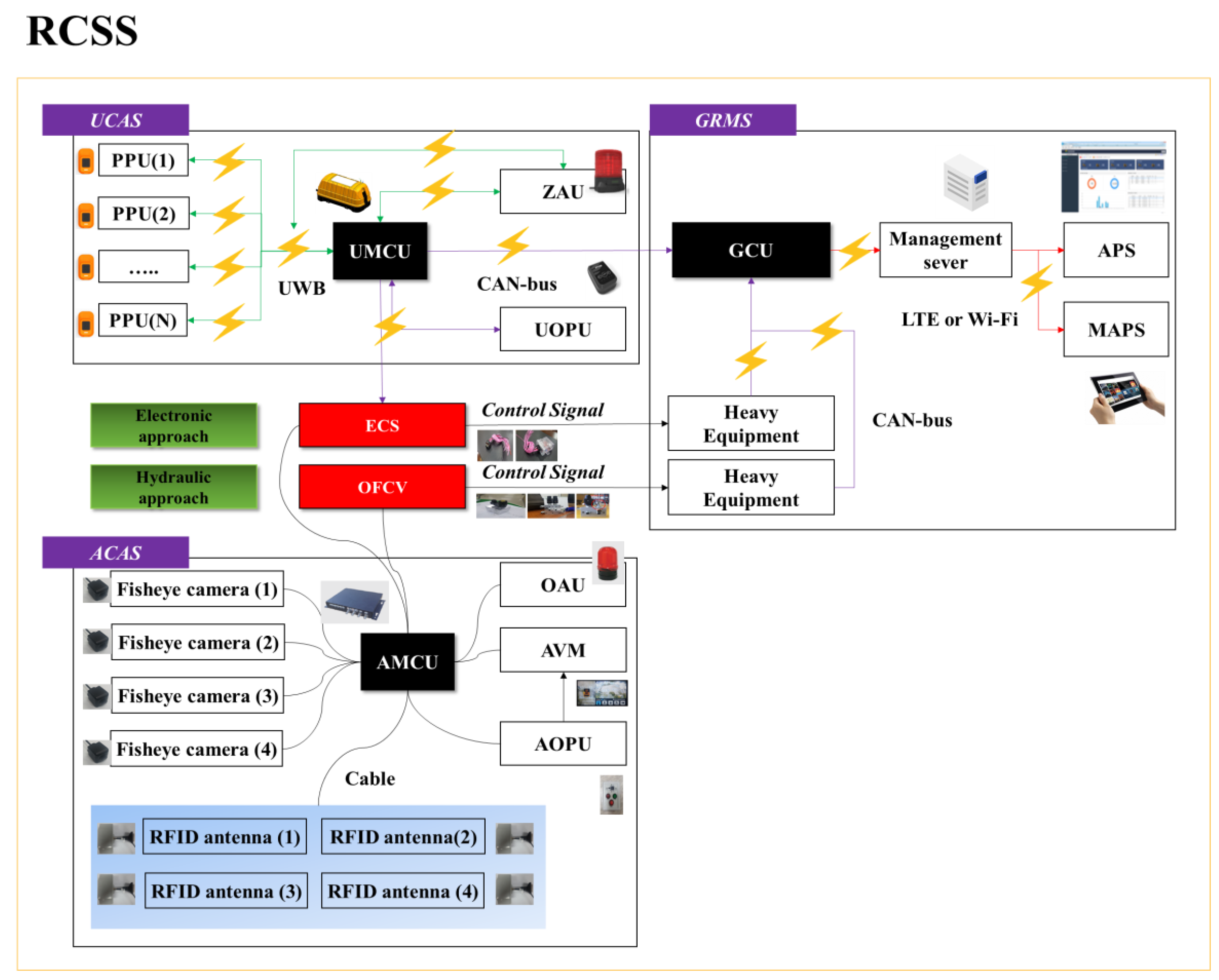
4. Operational Scenarios of Proposed System
- (a)
- Continuous and simultaneous monitoring of workers and construction equipment at construction sites;
- (b)
- Real-time warning to workers, equipment operators, and entire working space as the level of risk increases;
- (c)
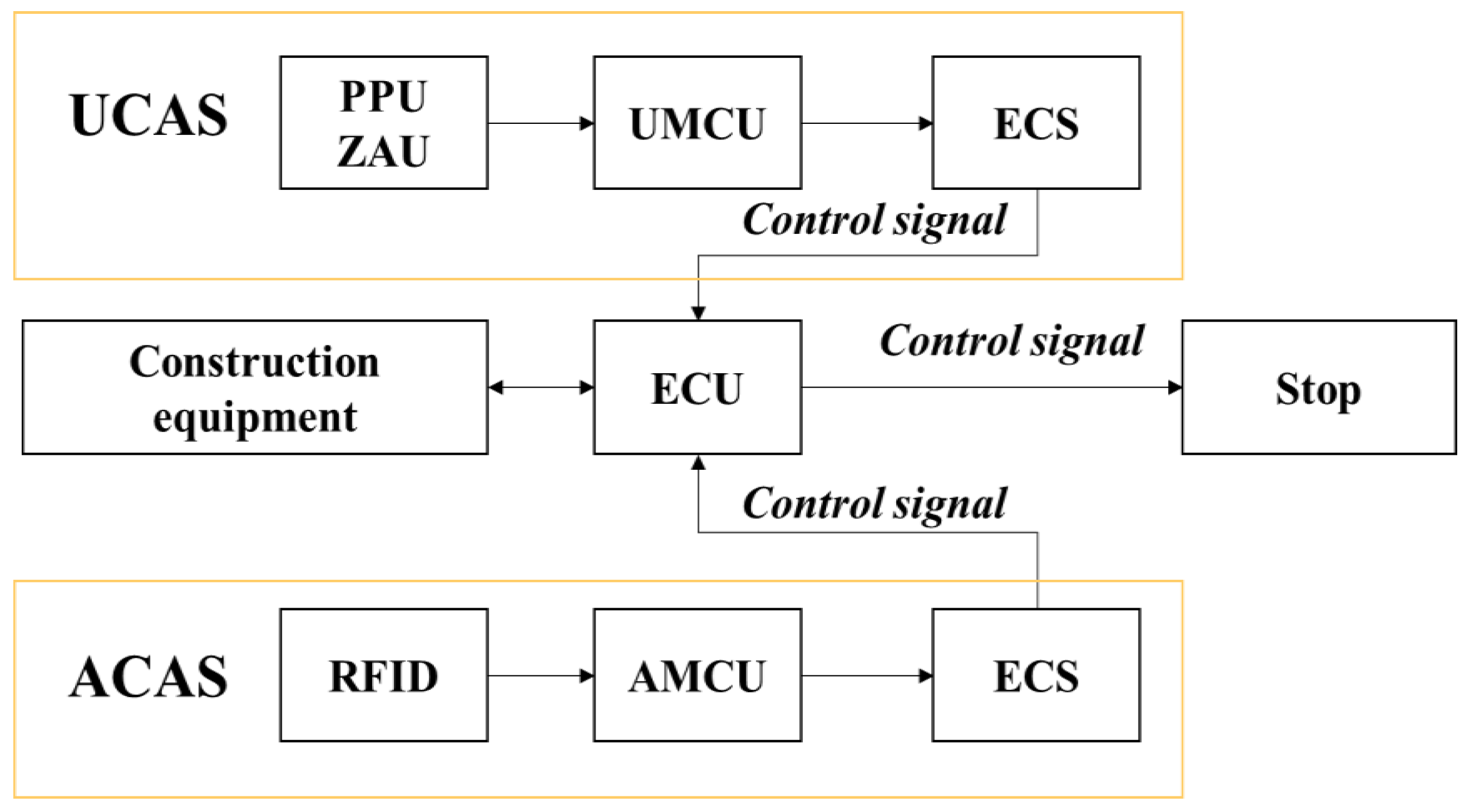
- Automatic controlling of construction equipment before the occurrence of a collision accident.
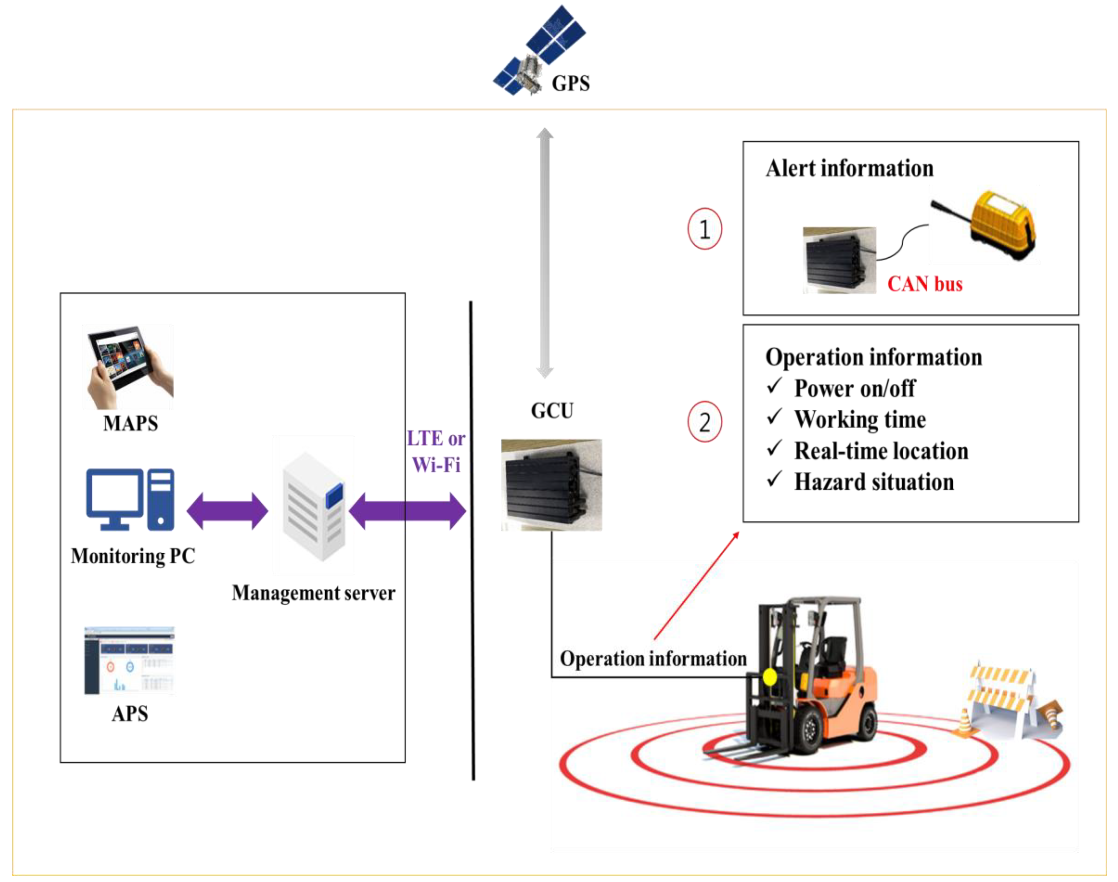
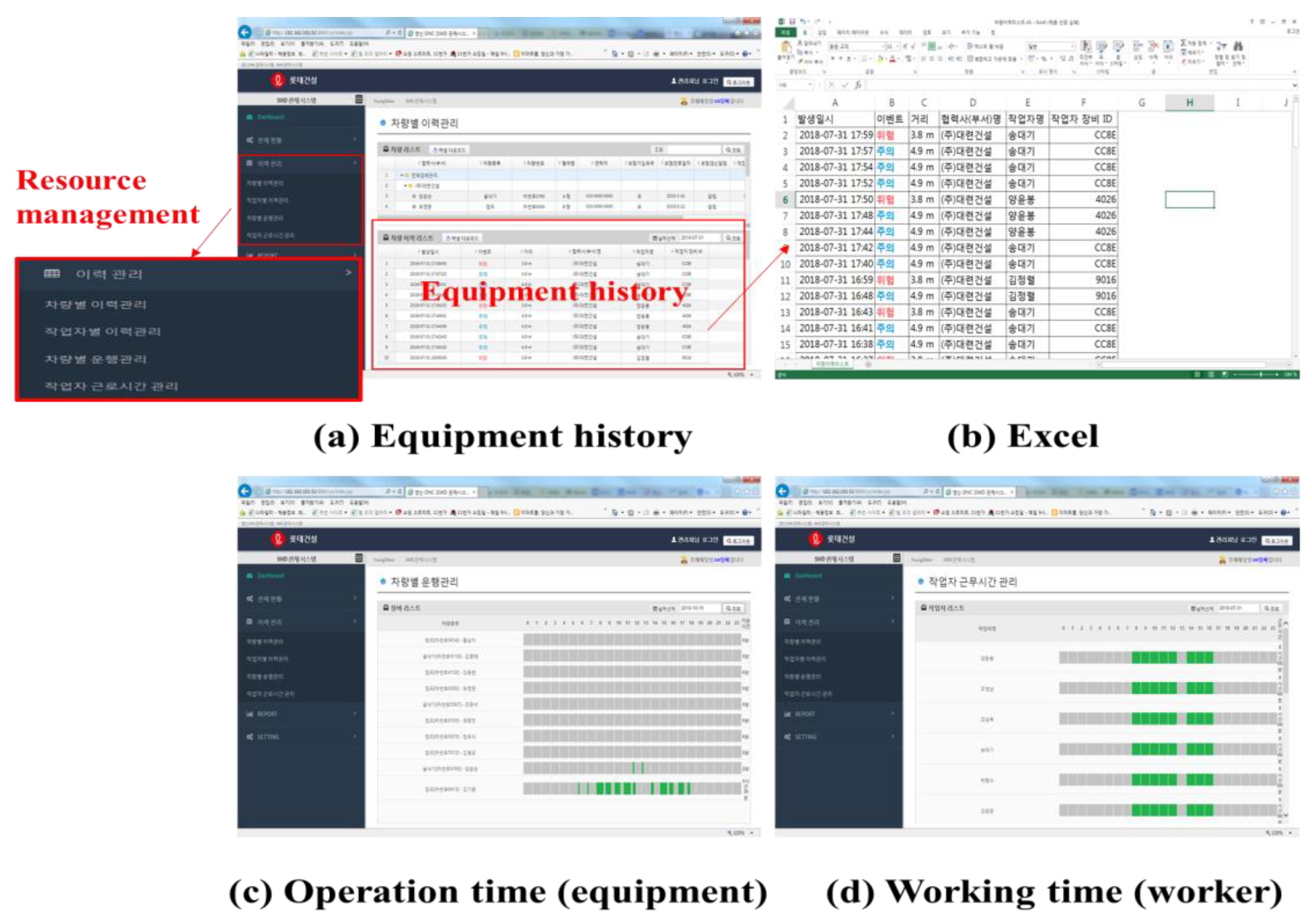
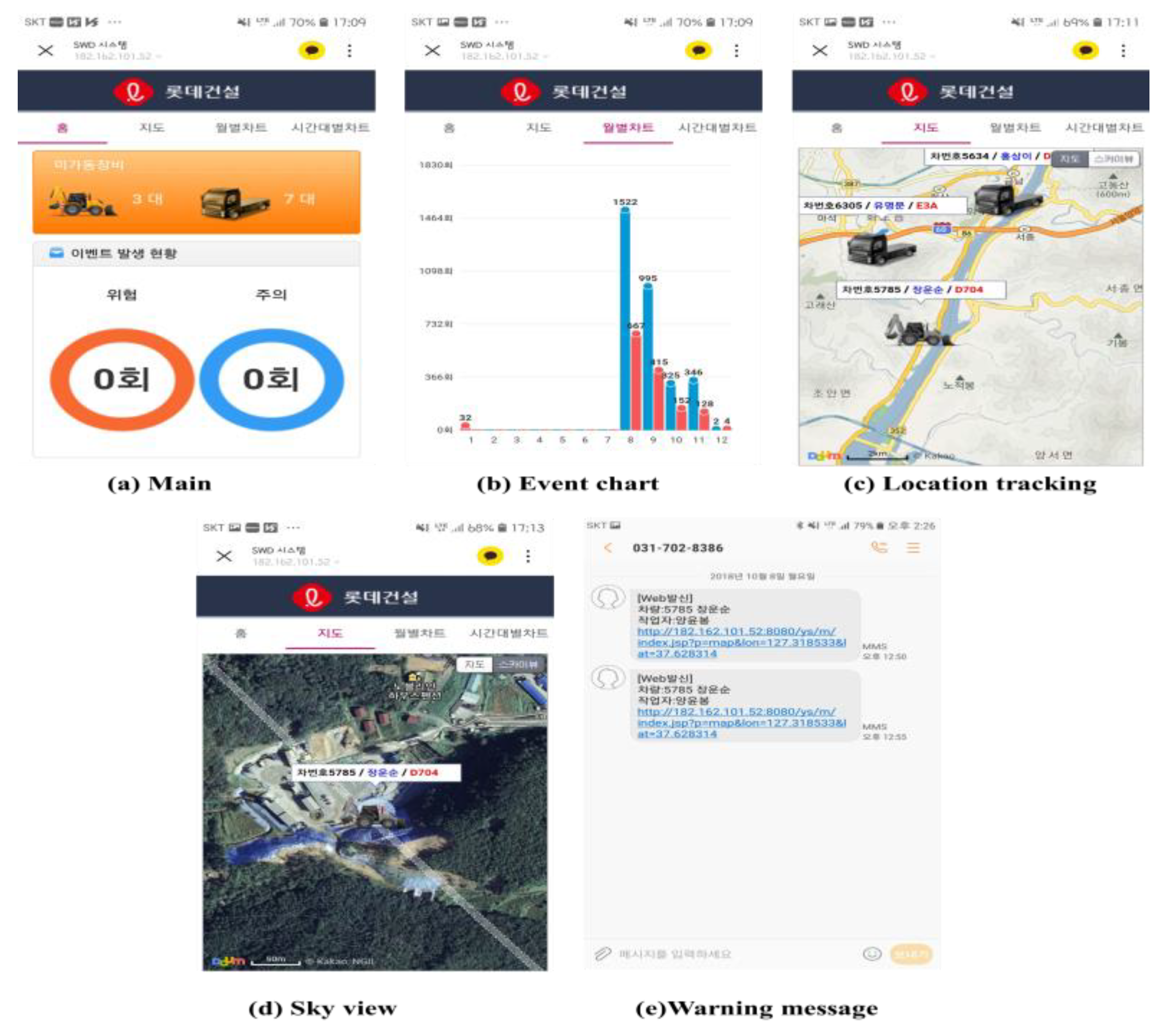
4.1. GRMS
4.2. UCAS and GRMS
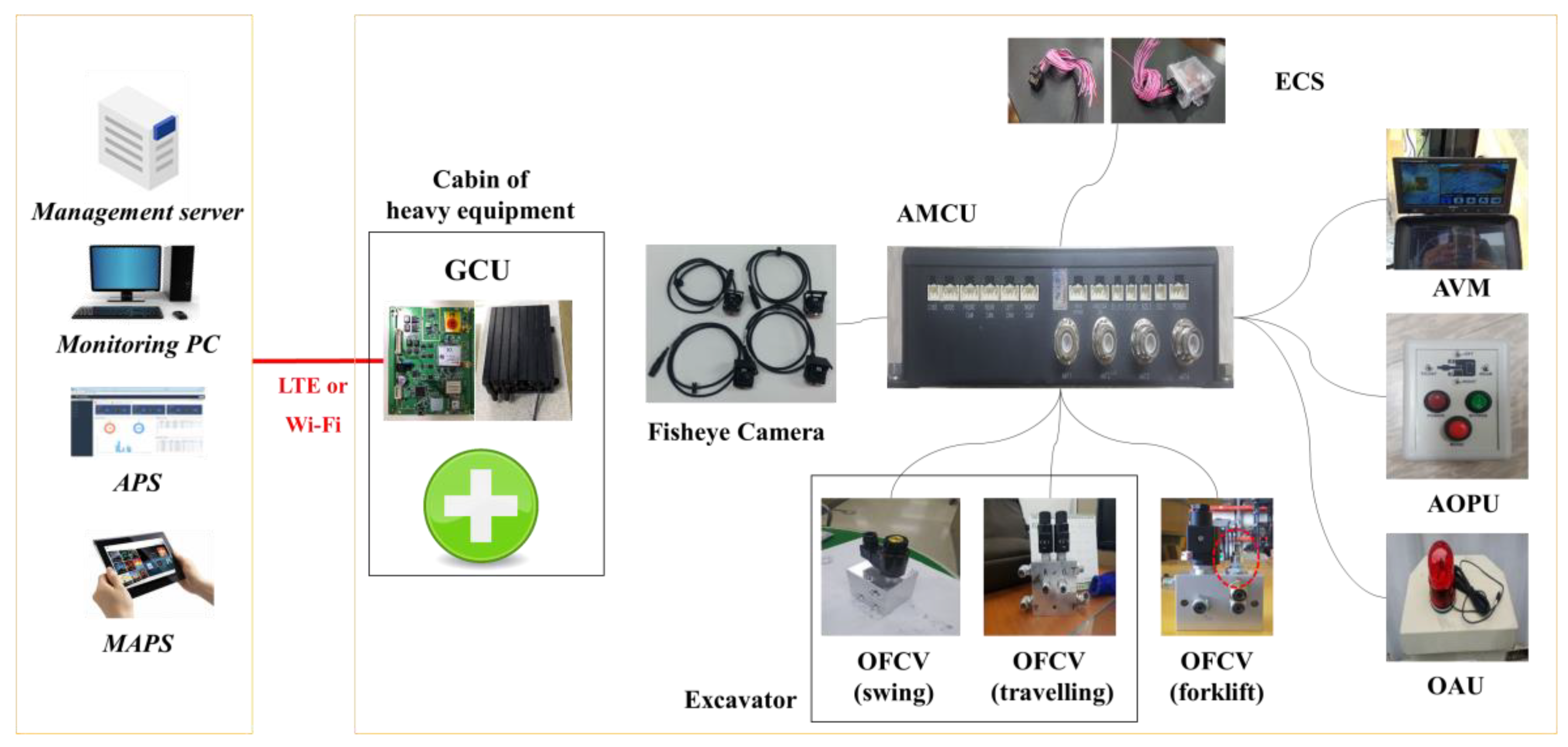
4.3. ACAS and GRMS
5. Performance Evaluation
5.1. Laboratory Scale Tests
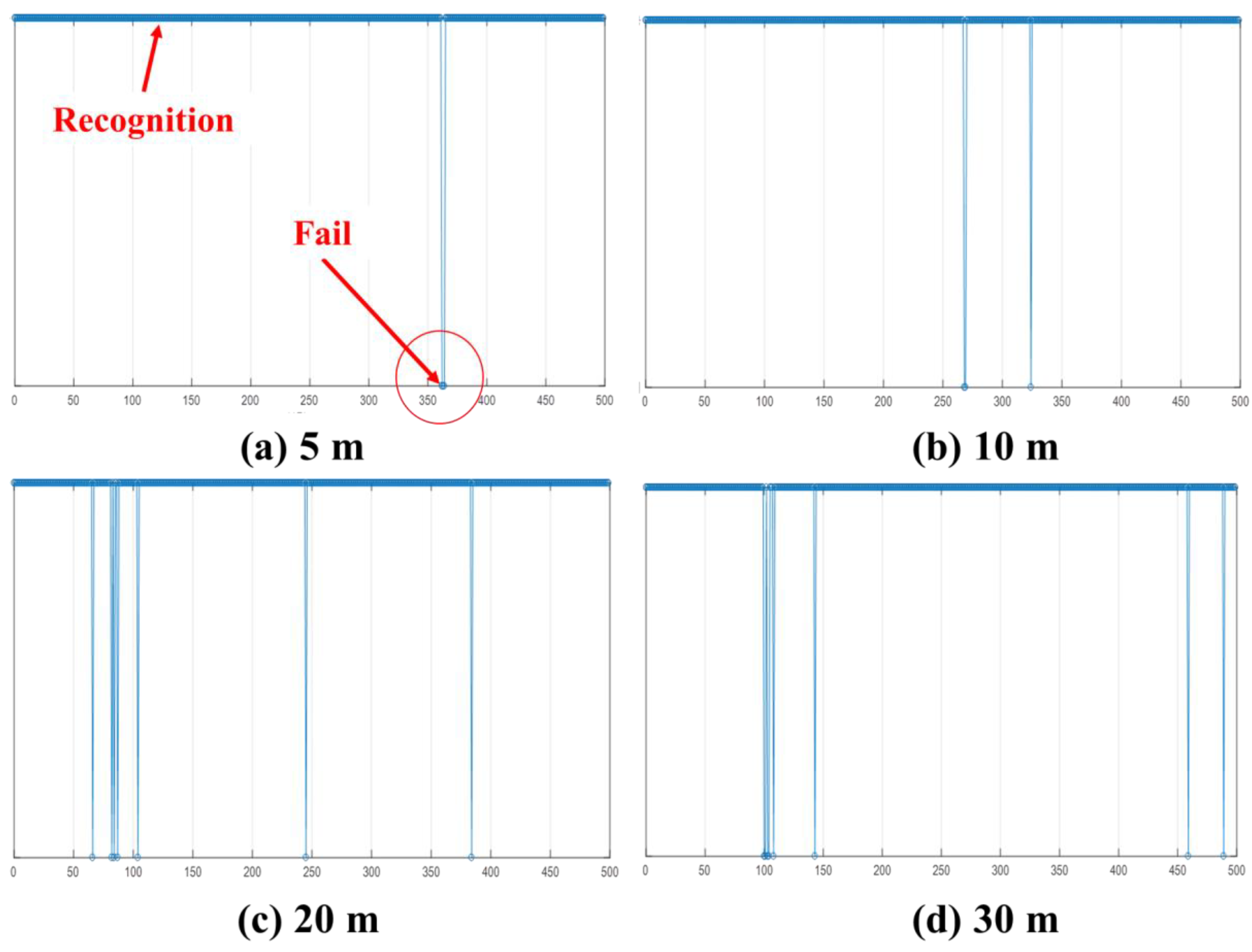
5.1.1. Recognition Rate per 500 times
5.1.2. Recognition Range Test
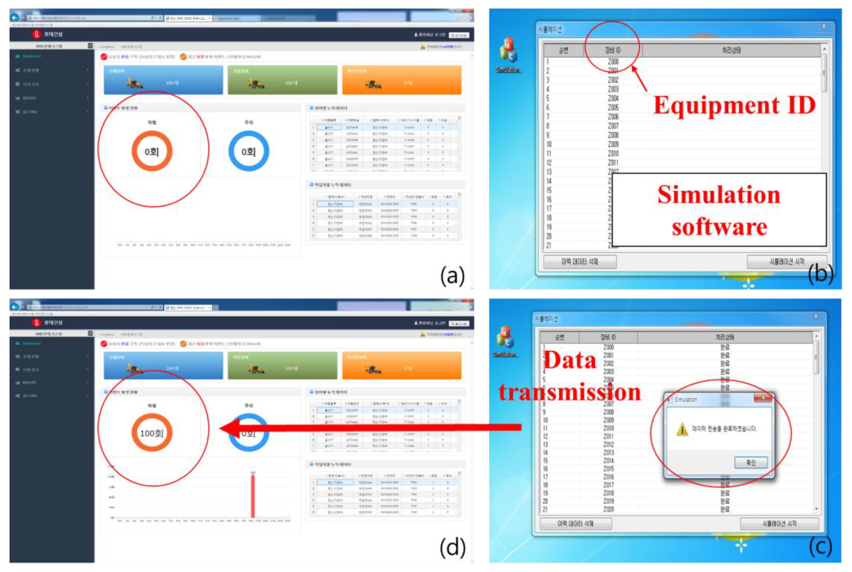
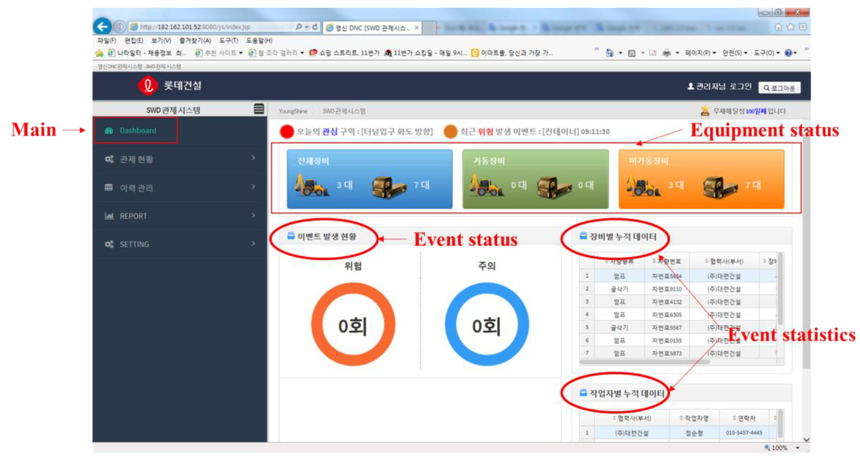
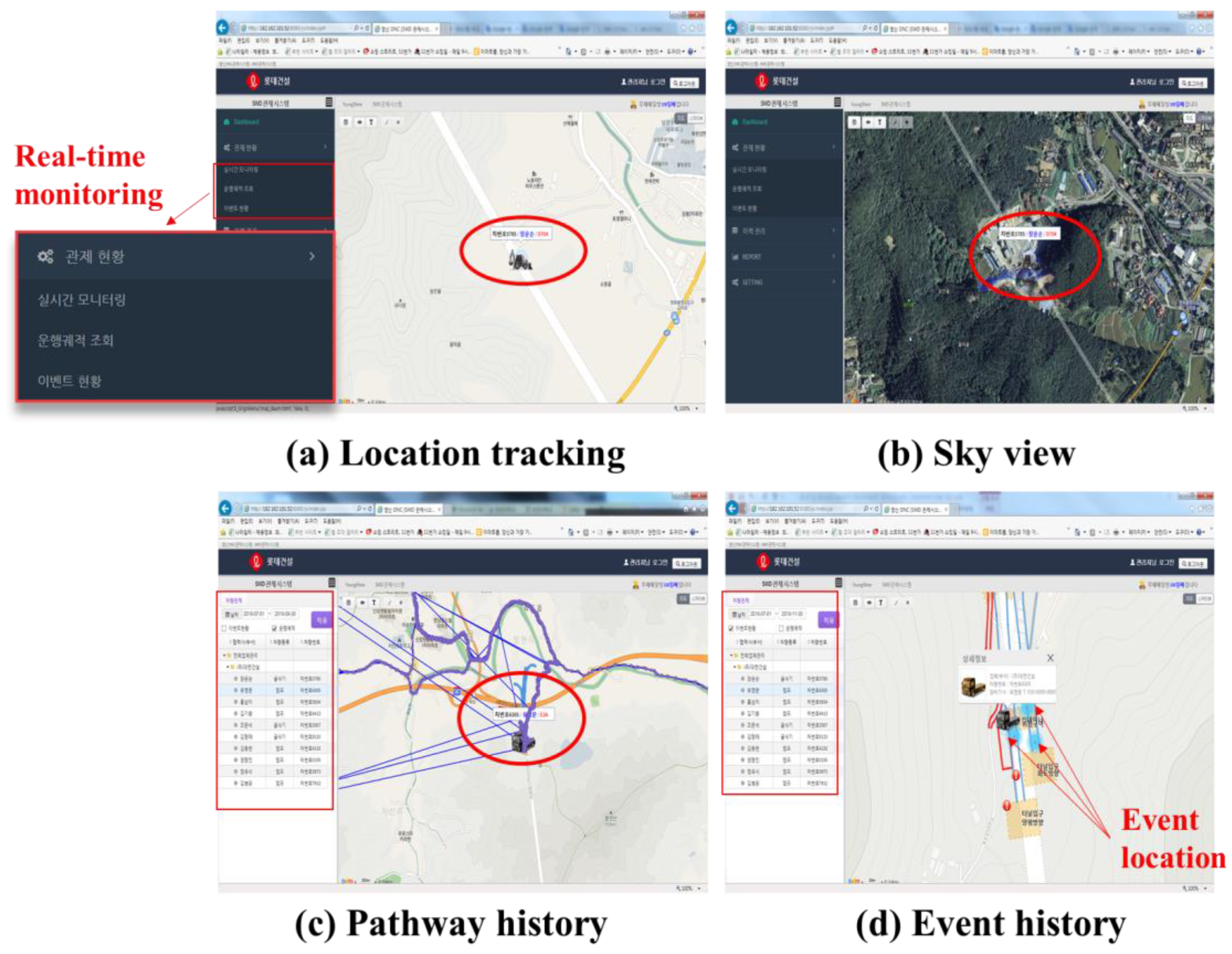
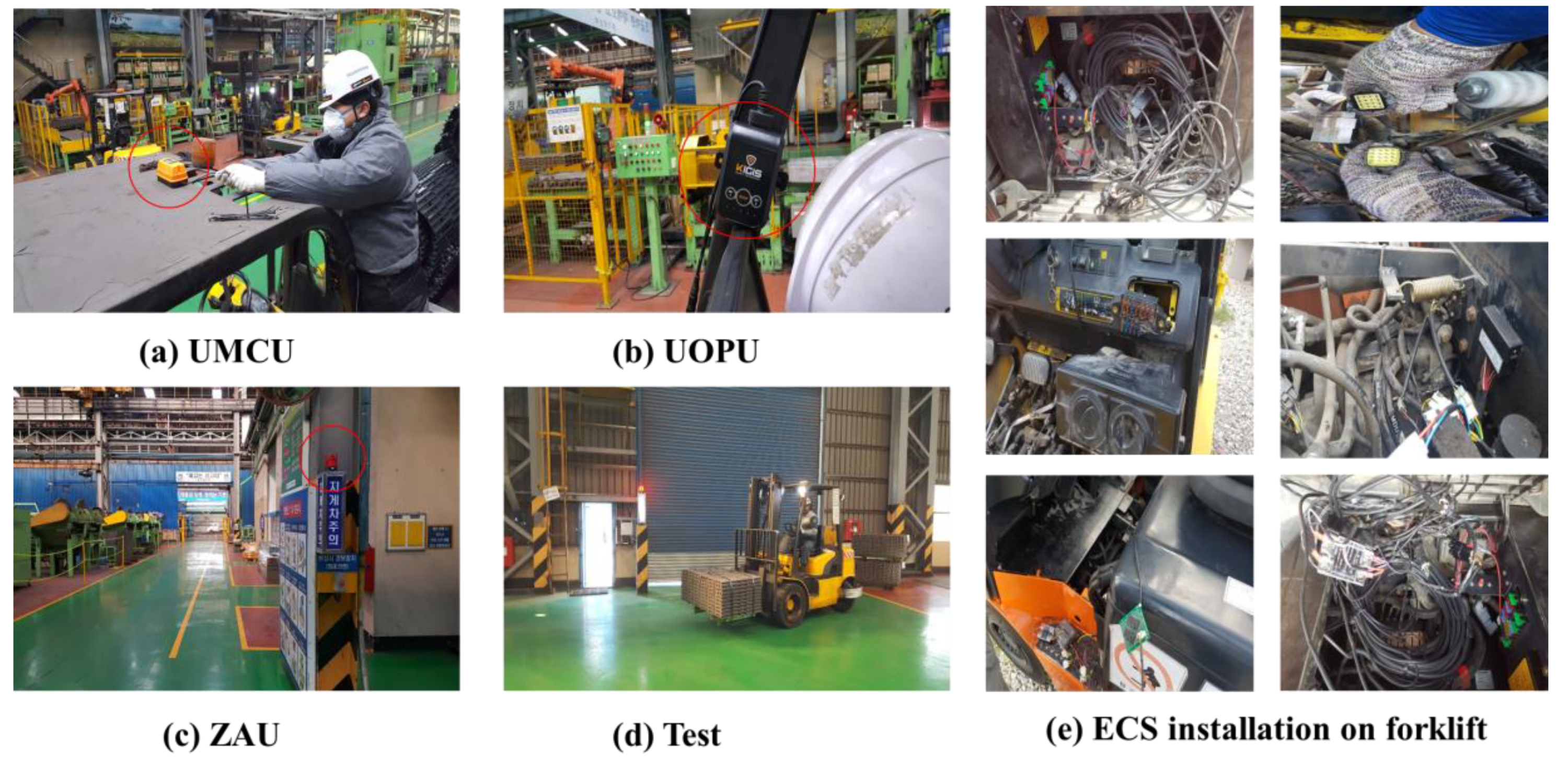
5.2. Real Field Validations
6. Conclusions
Author Contributions
Funding
Conflicts of Interest
References
- Zhou, W.; Whyte, J.; Sacks, R. Construction safety and digital design: A review. Autom. Constr. 2012, 22, 102–111. [Google Scholar] [CrossRef]
- Koreatimes. Available online: http://www.koreatimes.co.kr/www/news/nation/2010/04/113_64827.html# (accessed on 8 December 2018).
- Behzadan, A.H.; Aziz, Z.; Anumba, C.J.; Kamat, V.R. Ubiquitous location tracking for context-specific information delivery on construction sites. Autom. Constr. 2008, 17, 737–748. [Google Scholar] [CrossRef]
- U.S. Bureau of Labor. An Analysis of Fatal Occupational Injuries at Road Construction Sites. 2003–2010. Available online: https://www.bls.gov/opub/mlr/2013/article/an-analysis-of-fatal-occupational-injuries-at-road-construction-sites-2003-2010.htm (accessed on 10 December 2018).
- Jo, B.W.; Lee, Y.S.; Kim, J.H.; Khan, R.M.A. Trend analysis of construction industrial accidents in korea from 2011 to 2015. Sustainability 2017, 9, 1297. [Google Scholar] [CrossRef]
- Fosbroke, D. Niosh reports! Studies on heavy equipment blind spots and internal traffic control. In Proceedings of the 2004 Roadway Work Zone Safety & Health Conference, Baltimore, MD, USA, 4 November 2004. [Google Scholar]
- Ray, S.J.; Teizer, J. Computing 3d blind spots of construction equipment: Implementation and evaluation of an automated measurement and visualization method utilizing range point cloud data. Autom. Constr. 2013, 36, 95–107. [Google Scholar] [CrossRef]
- Rashid, B.; Rehmani, M.H. Applications of wireless sensor networks for urban areas: A survey. J. Netw. Comput. Appl. 2016, 60, 192–219. [Google Scholar] [CrossRef]
- Zhu, Z.; Park, M.-W.; Koch, C.; Soltani, M.; Hammad, A.; Davari, K. Predicting movements of onsite workers and mobile equipment for enhancing construction site safety. Autom. Constr. 2016, 68, 95–101. [Google Scholar] [CrossRef]
- Park, J.; Marks, E.; Cho, Y.K.; Suryanto, W. Performance test of wireless technologies for personnel and equipment proximity sensing in work zones. J. Constr. Eng. Manag. 2015, 142, 04015049. [Google Scholar] [CrossRef]
- Nieto, A.; Miller, S.; Miller, R. Gps proximity warning system for at-rest large mobile equipment. Int. J. Surf. Min. Reclam. Environ. 2005, 19, 75–84. [Google Scholar] [CrossRef]
- Commission, F.C. FCC Notice of Proposed Rule Making, Revision of Part 15 of the Commission’s Rules Regarding Ultrawideband Transmission Systems; Federal Communications Commission: Washington, DC, USA, 2005; pp. 98–153. [Google Scholar]
- Foerster, J.; Green, E.; Somayazulu, S.; Leeper, D. Ultra-wideband technology for short-or medium-range wireless communications. Intel Technol. J. 2001, 2, 1–11. [Google Scholar]
- Fontana, R.J. Recent system applications of short-pulse ultra-wideband (UWB) technology. IEEE Trans. Microw. Theory Tech. 2004, 52, 2087–2104. [Google Scholar] [CrossRef]
- Carbonari, A.; Giretti, A.; Naticchia, B. A proactive system for real-time safety management in construction sites. Autom. Constr. 2011, 20, 686–698. [Google Scholar] [CrossRef]
- Liu, H.; Darabi, H.; Banerjee, P.; Liu, J. Survey of wireless indoor positioning techniques and systems. IEEE Trans. Syst. Man Cybern. Part C 2007, 37, 1067–1080. [Google Scholar] [CrossRef]
- Administration-MSHA. Safety Standards for Surface Haulage-Proposed Rule. Available online: https://arlweb.msha.gov/REGS/FEDREG/PROPOSED/1998PROP/98-20351.HTM (accessed on 21 September 2018).
- Marks, E.D.; Teizer, J. Method for testing proximity detection and alert technology for safe construction equipment operation. Constr. Manag. Econ. 2013, 31, 636–646. [Google Scholar] [CrossRef]
- Ruff, T. Recommendations for Evaluating and Implementing Proximity Warning Systems on Surface Mining Equipment; National Institute for Occupational Safety and Health: Washington, DC, USA, 2007. [Google Scholar]
- Ruff, T.M. Monitoring blind spots: A major concern for haul trucks. Eng. Min. J. 2001, 202, 17. [Google Scholar]
- Ruff, T.M. Test Results of Collision Warning Systems for Surface Mining Dump Trucks; National Institute for Occupational Safety and Health: Washington, DC, USA, 2000. [Google Scholar]
- Marks, E.; Teizer, J. Real-time proactive equipment operator and ground worker warning and alert system in steel manufacturing. Iron Steel Technol. 2012, 9, 56–69. [Google Scholar]
- Park, J.; Kim, K.; Cho, Y.K. Framework of automated construction-safety monitoring using cloud-enabled bim and ble mobile tracking sensors. J. Constr. Eng. Manag. 2016, 143, 05016019. [Google Scholar] [CrossRef]
- Kim, H.; Lee, H.-S.; Park, M.; Chung, B.; Hwang, S. Automated hazardous area identification using laborers' actual and optimal routes. Autom. Constr. 2016, 65, 21–32. [Google Scholar] [CrossRef]
- Chae, S.; Yoshida, T. Application of rfid technology to prevention of collision accident with heavy equipment. Autom. Constr. 2010, 19, 368–374. [Google Scholar] [CrossRef]
- Vahdatikhaki, F.; Hammad, A. Dynamic equipment workspace generation for improving earthwork safety using real-time location system. Adv. Eng. Inform. 2015, 29, 459–471. [Google Scholar] [CrossRef]
- Schiffbauer, W.H. Active proximity warning system for surface and underground mining applications. Min. Eng. 2002, 54, 40–48. [Google Scholar]
- Sabniveesu, V.; Kavuri, A.; Kavi, R.; Kulathumani, V.; Kecojevic, V.; Nimbarte, A. Use of wireless, ad-hoc networks for proximity warning and collision avoidance in surface mines. Int. J. Min. Reclam. Environ. 2015, 29, 331–346. [Google Scholar]
- Luo, X.; Li, H.; Huang, T.; Rose, T. A field experiment of workers’ responses to proximity warnings of static safety hazards on construction sites. Saf. Sci. 2016, 84, 216–224. [Google Scholar] [CrossRef]
- Lee, U.-K.; Kim, J.-H.; Cho, H.; Kang, K.-I. Development of a mobile safety monitoring system for construction sites. Autom. Constr. 2009, 18, 258–264. [Google Scholar] [CrossRef]
- Wu, W.; Yang, H.; Chew, D.A.S.; Yang, S.-h.; Gibb, A.G.F.; Li, Q. Towards an autonomous real-time tracking system of near-miss accidents on construction sites. Autom. Constr. 2010, 19, 134–141. [Google Scholar] [CrossRef]
- Yang, H.; Chew, D.A.S.; Wu, W.; Zhou, Z.; Li, Q. Design and implementation of an identification system in construction site safety for proactive accident prevention. Accid. Anal. Prev. 2012, 48, 193–203. [Google Scholar] [CrossRef] [PubMed]
- Ruff, T.M.; Holden, T.P. Preventing collisions involving surface mining equipment: A GPS-based approach. J. Saf. Res. 2003, 34, 175–181. [Google Scholar] [CrossRef]
- Vega, A.N. Development of a Real-Time Proximity Warning and 3-D Mapping System Based on Wireless Networks, Virtual Reality Graphics, and GPS to Improve Safety in Open-Pit Mines; Colorado School of Mines: Golden, CO, USA, 2001. [Google Scholar]
- Wu, H.; Tao, J.; Li, X.; Chi, X.; Li, H.; Hua, X.; Yang, R.; Wang, S.; Chen, N. A location based service approach for collision warning systems in concrete dam construction. Saf. Sci. 2013, 51, 338–346. [Google Scholar] [CrossRef]
- Schmidt, D. Teck, Safemine Team Up for Collision Avoidance System; Coal Age: Jacksonville, FL, USA, 2014. [Google Scholar]
- Teizer, J. Wearable, wireless identification sensing platform: Self-monitoring alert and reporting technology for hazard avoidance and training (smarthat). J. Inf. Technol. Constr. (ITcon) 2015, 20, 295–312. [Google Scholar]
- Seo, J.; Han, S.; Lee, S.; Kim, H. Computer vision techniques for construction safety and health monitoring. Adv. Eng. Inform. 2015, 29, 239–251. [Google Scholar] [CrossRef]
- Choe, S.; Leite, F.; Seedah, D.; Caldas, C. Evaluation of sensing technology for the prevention of backover accidents in construction work zones. J. Inf. Technol. Constr. (ITcon) 2014, 19, 1–19. [Google Scholar]
- Naticchia, B.; Vaccarini, M.; Carbonari, A. A monitoring system for real-time interference control on large construction sites. Autom. Constr. 2013, 29, 148–160. [Google Scholar] [CrossRef]
- Cheng, T.; Venugopal, M.; Teizer, J.; Vela, P. Performance evaluation of ultra wideband technology for construction resource location tracking in harsh environments. Autom. Constr. 2011, 20, 1173–1184. [Google Scholar] [CrossRef]
- Teizer, J.; Allread, B.S.; Fullerton, C.E.; Hinze, J. Autonomous pro-active real-time construction worker and equipment operator proximity safety alert system. Autom. Constr. 2010, 19, 630–640. [Google Scholar] [CrossRef]
- Jo, B.-W.; Lee, Y.-S.; Kim, J.-H.; Kim, D.-K.; Choi, P.-H. Proximity warning and excavator control system for prevention of collision accidents. Sustainability 2017, 9, 1488. [Google Scholar] [CrossRef]


| Proximity Sensing Technology | Main Advantage | Limitation |
|---|---|---|
| Ultrasound | ✓ Low initial cost ✓ Minimal device required ✓ Simplicity of installation | ✓ Sensitive to the surrounding environment ✓ Limited detection range ✓ It requires direct line of sight ✓ Multiple sensors are required to cover the width of a large equipment |
| Radar | ✓ Minimal device required | ✓ It is difficult to distinguish between workers and other objects. |
| Camera (computer vision) | ✓ Wide observation range ✓ It can easily distinguish a worker from other objects | ✓ It’s performance depends on proper lighting ✓ Additional image processing technology required |
| RFID | ✓ Capable of multiple antenna application ✓ Tag price is lower than UWB sensor | ✓ Relatively limited detection range ✓ RFID tag should be provided to all objects for sensing |
| UWB | ✓ Wide detection range ✓ Can function on outdoor and indoor ✓ It can easily distinguish a worker from other objects | ✓ UWB device should be provided to all objects (worker or equipment) |
| GPS | ✓ Can be used to location tracking | ✓ Not functional indoors ✓ Not suitable for close range sensing |
- RFID: Radio Frequency Identification
- UWB: Ultra-Wideband
- GPS: Global Positioning System
| Classification | Communication Protocol |
|---|---|
| PPU-ZAU | UWB |
| UMCU-PPU | UWB |
| UMCU-ZAU | UWB |
| UMCU-GCU | CAN bus |
| UMCU-UOPU | CAN bus |
| UMCU-ECS | CAN bus |
| GCU-server | LTE or Wi-Fi |
- PPU: Personal Protection Unit
- ZAU: Zone Alert Unit
- UWB: Ultra-Wideband
- UMCU: UWB Main Control Unit
- UOPU: UWB Operator Protection Unit
- CAN: Controller Area Network
- GCU: Global Positioning System Communication Unit
- LTE: Long-Term Evolution
- ECS: Electronic Control Sensor
| Characteristics | GPS | Radar | Magnetic Sensing | Ultrasound | RFID | UWB |
|---|---|---|---|---|---|---|
| Detection range | Long | Short/Medium | Short | Short | Short/Medium | Long |
| Accuracy of data | DE* | Medium | Low/Medium | Low/Medium | Medium | High |
| Update rate | High | High | High | High | High | High |
| Two-way alert | Yes | No | Yes | No | Yes | Yes |
| Installation and setup difficulty | Low/Medium | Low/Medium | Medium | Low/Medium | Low/medium | Low |
| Relative frequency of false alarms | Low | Medium | Low | Medium | Low | Medium |
| Tolerance to mud, dust etc. | High | Medium | High | High | High | Medium |
| Cost | Low/Medium | Low/Medium | Medium/High | Low | High | Low |
| Classification | Factors | |
|---|---|---|
| GCU | Interface 1 | CAN 2.0 bus |
| Interface 2 | LTE(WCDMA) | |
| Location tracking | GPS | |
| Data type 1 | Timestamp (for GMT and local time) | |
| Time offset (e.g.: GMT+00:00) | ||
| GPS coordinates | ||
| Status of GCU | ||
| Status of equipment | ||
| Data type 2 (with UCAS) | ID of UMCU / PPU / ZAU | |
| Event(eq. alert stats) | ||
| Design |  | |
| Classification | Factors | |
|---|---|---|
| UMCU | Size Interface 1 Interface 2 Mount Power UWB Frequency Bandwidth | (mm) CAN 2.0 bus UWB Flexible magnetic foot 12/24V 3993.6MHz 500MHz |
| PPU | Size Interface Mount Battery Alert type UWB frequency Bandwidth | (mm) UWB Helmet holder or belt clip 950 mAh Vibration and buzzer 3993.6MHz 500MHz |
| UOPU | Size Interface Alert type Power | CAN 2.0 bus LED and buzzer 12/24V |
| ZAU | Size Interface Interface Alert type Mount Power UWB frequency Bandwidth | 122.7 x 140.6(H) x 111.5 (mm) UWB CAN 2.0 bus LED and buzzer Flexible magnetic foot 12/24V 3993.6MHz 500MHz |
| ECS | Interface Power | CAN 2.0 bus 12/24V |
| Classification | OFCV Type | ||
|---|---|---|---|
| Excavator (Swing) | Excavator (Travelling) | Forklift | |
| Max. Flow | 32 lpm | 35 lpm | 35 lpm |
| Max. Pressure | 350 bar | 210 bar | 210 bar |
| Operating hydraulic oil | ISO VG16 ~VG68 | ISO VG16 ~VG68 | ISO VG16 ~VG68 |
| Design |  |  |  |
| Classification | Factors | |
|---|---|---|
| AVM | Display Resolution CPU processor UI Interface Alert type | HDMI, LVD8 MAX Dual Core 1.5 GHz Touch Screen CAN 2.0 bus Buzzer / Visual |
| Fisheye camera | Angle | V100°, H180° |
| AOPU | Alert type | LED and buzzer |
| OAU | Alert type | LED and buzzer |
| RFID antenna | Size Weight | (mm) 295 g |
| RFID tag | Type | ISO-1800-6C |
| AMCU(MC board) | Operation power Current Consumption | 24 ~ 32 V 2A(MAX. 24V) |
| AMCU(AVM board) | Input | 4 Port (Fisheye camera) |
| AMCU(RFID board) | Frequency Port | 917.3–920.3 MHz 4 Port (RFID antenna) |
| Distance(m) | Total | Fail | Success | Recognition Rate (%) |
|---|---|---|---|---|
| 5 | 500 | 3 | 497 | 99.4 |
| 10 | 500 | 3 | 497 | 99.4 |
| 20 | 500 | 7 | 493 | 98.6 |
| 30 | 500 | 8 | 492 | 98.4 |
| Angle | Distance | Angle | Distance | Angle | Distance | Angle | Distance |
|---|---|---|---|---|---|---|---|
| 0° | 9.8m | 100° | 9.7m | 190° | 9.5m | 280° | 9.6m |
| 10° | 9.3m | 110° | 9.5m | 200° | 9.6m | 290° | 9.5m |
| 20° | 9.4m | 120° | 9.6m | 210° | 9.7m | 300° | 9.8m |
| 30° | 9.2m | 130° | 9.5m | 220° | 9.5m | 310° | 9.3m |
| 40° | 9.4m | 140° | 9.6m | 230° | 9.7m | 320° | 9.3m |
| 50° | 9.4m | 150° | 9.6m | 240° | 9.6m | 330° | 9.6m |
| 60° | 9.6m | 160° | 9.5m | 250° | 9.5m | 340° | 9.4m |
| 70° | 9.7m | 170° | 9.6m | 260° | 9.6m | 350° | 9.5m |
| 80° | 9.5m | 180° | 9.4m | 270° | 9.5m | 360° | 9.8m |
| 90° | 9.4m |
| Angle | Distance | Angle | Distance | Angle | Distance | Angle | Distance |
|---|---|---|---|---|---|---|---|
| 0° | 7.8m | 100° | 7.9m | 190° | 7.9m | 280° | 7.0m |
| 10° | 7.4m | 110° | 7.3m | 200° | 6.7m | 290° | 7.4m |
| 20° | 6.8m | 120° | 7.4m | 210° | 7.4m | 300° | 7.0m |
| 30° | 6.9m | 130° | 6.9m | 220° | 7.7m | 310° | 7.4m |
| 40° | 7.0m | 140° | 6.8m | 230° | 7.6m | 320° | 7.6m |
| 50° | 7.1m | 150° | 8.0m | 240° | 7.7m | 330° | 8.2m |
| 60° | 7.7m | 160° | 7.2m | 250° | 7.6m | 340° | 7.6m |
| 70° | 7.4m | 170° | 6.6m | 260° | 7.2m | 350° | 8.0m |
| 80° | 7.2m | 180° | 7.1m | 270° | 8.0m | 360° | 7.8m |
| 90° | 7.6m |
© 2019 by the authors. Licensee MDPI, Basel, Switzerland. This article is an open access article distributed under the terms and conditions of the Creative Commons Attribution (CC BY) license (http://creativecommons.org/licenses/by/4.0/).
Share and Cite
Jo, B.-W.; Lee, Y.-S.; Khan, R.M.A.; Kim, J.-H.; Kim, D.-K. Robust Construction Safety System (RCSS) for Collision Accidents Prevention on Construction Sites. Sensors 2019, 19, 932. https://doi.org/10.3390/s19040932
Jo B-W, Lee Y-S, Khan RMA, Kim J-H, Kim D-K. Robust Construction Safety System (RCSS) for Collision Accidents Prevention on Construction Sites. Sensors. 2019; 19(4):932. https://doi.org/10.3390/s19040932
Chicago/Turabian StyleJo, Byung-Wan, Yun-Sung Lee, Rana Muhammad Asad Khan, Jung-Hoon Kim, and Do-Keun Kim. 2019. "Robust Construction Safety System (RCSS) for Collision Accidents Prevention on Construction Sites" Sensors 19, no. 4: 932. https://doi.org/10.3390/s19040932
APA StyleJo, B.-W., Lee, Y.-S., Khan, R. M. A., Kim, J.-H., & Kim, D.-K. (2019). Robust Construction Safety System (RCSS) for Collision Accidents Prevention on Construction Sites. Sensors, 19(4), 932. https://doi.org/10.3390/s19040932