Environmental Monitoring with Distributed Mesh Networks: An Overview and Practical Implementation Perspective for Urban Scenario †

 ,
,  ,
,  , and
, and 
Abstract
1. Introduction
- Modern environmental monitoring applications and scenarios are reviewed.
- The pairwise key-based authentication mechanism was applied for urban environmental monitoring, allowing to handle individual system operational phases, e.g., the addition of new nodes, (un-)authorized migration of the node from one network segment to another, etc.
- An analytical framework based on Markov chain analysis that allows evaluating potential network topology changes is presented.
- A prototype of the proposed secure distrusted sensor network (operating based on the discussed authentication mechanism) was deployed in a real-life scenario.
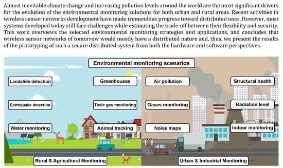
2. Overview on Environmental Monitoring Applications and Main Security Specifics
3. System Description and Problem Statement
- Simplex mode: The operation of the system is executed according to the “star” topology, and the transmission of messages to the Access Pontes (APs) directly using a controlled sleep mode.
- Duplex mode: The operation of the system is executed according the mesh network mode with relaying via the closest network nodes using a controlled sleep mode.
- Half-duplex mode: The operation the system is executed via the star topology but using a predefined sleep mode, i.e., the preset of the optimal mode for a given scenario and operating conditions are applied.
4. Security and Scalability for Environmental Monitoring Sensor Networks
- Gateway or Access Point (AP) is used for the end-node data aggregation. APs could also perform edge preprocessing of the incoming sensor data before the cloud delivery. Each data packet from each sensor node is encrypted using cloud public key to provide an additional level of the data integrity.
- Monitoring nodes are equipped with different sensing devices with the primary goal of collecting the specified environmental parameters, e.g., temperature, humidity, noise level, etc. The nodes could either connect directly to the AP or relay the data through the neighboring nodes to the AP in the ad hoc-like way.
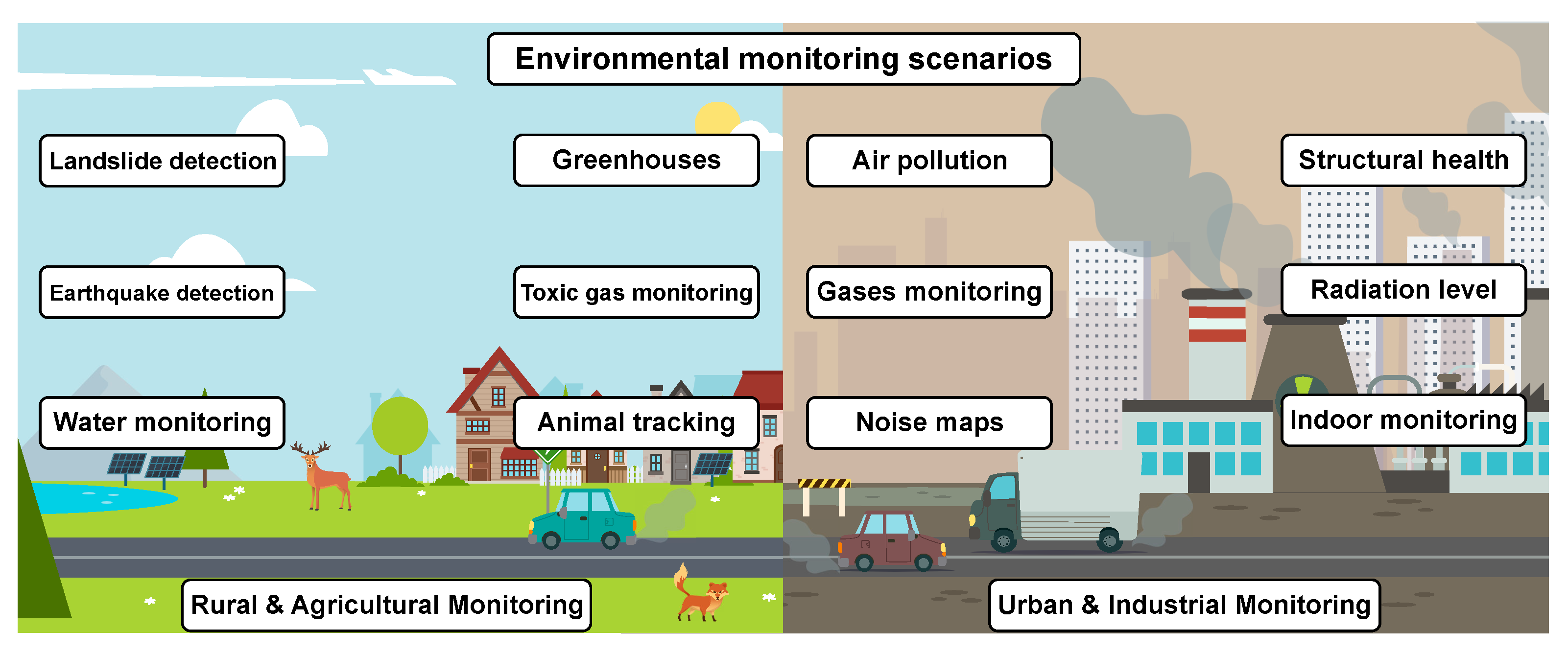
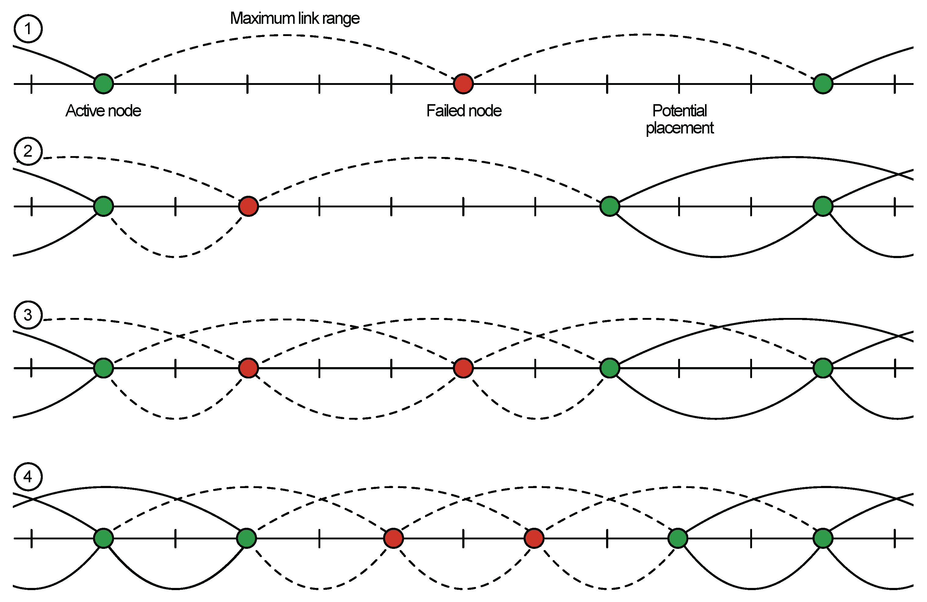
- Sensor initialization (addition): For example, a phase when a new node should be connected to any available node or AP in range (see Figure 2, Case 1). Assuming that both devices are operating in the same predefined way from the information security point of view, we consider two possible scenarios:
- Simultaneous initialization of several sensors in one secure network. This situation is common for initial network deployment when a number of devices is more than two, .
- Adding a single new sensor to an existing secure sensor network.
- Stable sensor network operation: In this scenario, sensors are neither added nor excluded from existing topology, and their logical position is static with respect to their neighbor nodes (see Figure 2, Case 2).
- Sensor migration: In this scenario, the network faces the topology change (see Figure 2, Case 3) that could be caused by different factors:
- Legally moved sensor is within the network segment with established pairwise relation;
- Illegally moved sensor.
- Sensor removal: In this scenario, two possible scenarios may be present:
- Removed sensor is excluded from a particular secure network and could be used in the future only through new node initialization procedure.
- Removed sensor is migrated to another segment of an existing network without reinitialization.
- The master key used on the initialization step is not removed and is kept in the so-called tamper resistance memory of the node [56]. This approach allows us to change the configuration of the network by simple displacement of the earlier installed node from one segment of the secure network to another (see Figure 2, Case 3). The displaced node can then authenticate with any other neighboring node in the same network if the nodes have the same master key. However, this feature becomes a disadvantage in the case it is necessary to prevent illegal movement (for example, if there is a need to be aware of the actual location of each node [57]). In this case, we should utilize an additional user authentication protocol for the system operator, which is required to make legal replacement of the active node, i.e., only the authenticated user should have an opportunity to move the sensor from one segment of the secure network to another. Any unauthorized movement should be prohibited.
- The master key used at the step of initialization is destroyed after predefined time calculated from the moment when the initialization step was completed [55]. This scenario strongly limits the possibility of previously installed sensor movement from the initial sensor network segment to another part of the same network. This feature of the protocol allows obtaining a rather stable structure of the network. In this case, the probability of getting false information from the nodes is significantly reduced due to the location change.
4.1. First Initialization of Several Sensors for New Secure Sensor Network
- Initially, the master key is defined for a new secure network. Each node i has its own unique identification number , for . Next, we define one-way function—.
- During the initial initialization, nodes can only exchange data in wireless link range, as depicted in Figure 2 (Case 2). Here, sensors 1, 2 and 3 exchange their unique IDs , and .
- Each of the nodes utilizes the information about unique IDs of other sensors and the master key to calculate pair-wise keys for mutual authentication. For example, sensor 1 calculates pair keys for sensors 2 and 3 as:where stands for the concatenation.Consequentially, sensors 2 and 3 also calculate the same pair-wise keys for the sensor 1:
- To provide the scalability, each sensor also calculates auxiliary key for adding new sensors in the future.
- Each sensor removes its master key after predefined interval from the first initialization process. This way, sensor 1 in Figure 2 (Case 2) would have the same information after the end of the initialization phase.
4.2. Stable Sensor Network Operation
4.3. Adding New Sensor to Existing Secure Sensor Network
4.4. Legal Sensor Moving to Another Secure Sensor Network Segment of Existing Network
4.5. Illegal Sensor Moving to Another Secure Sensor Network Segment of Existing Network
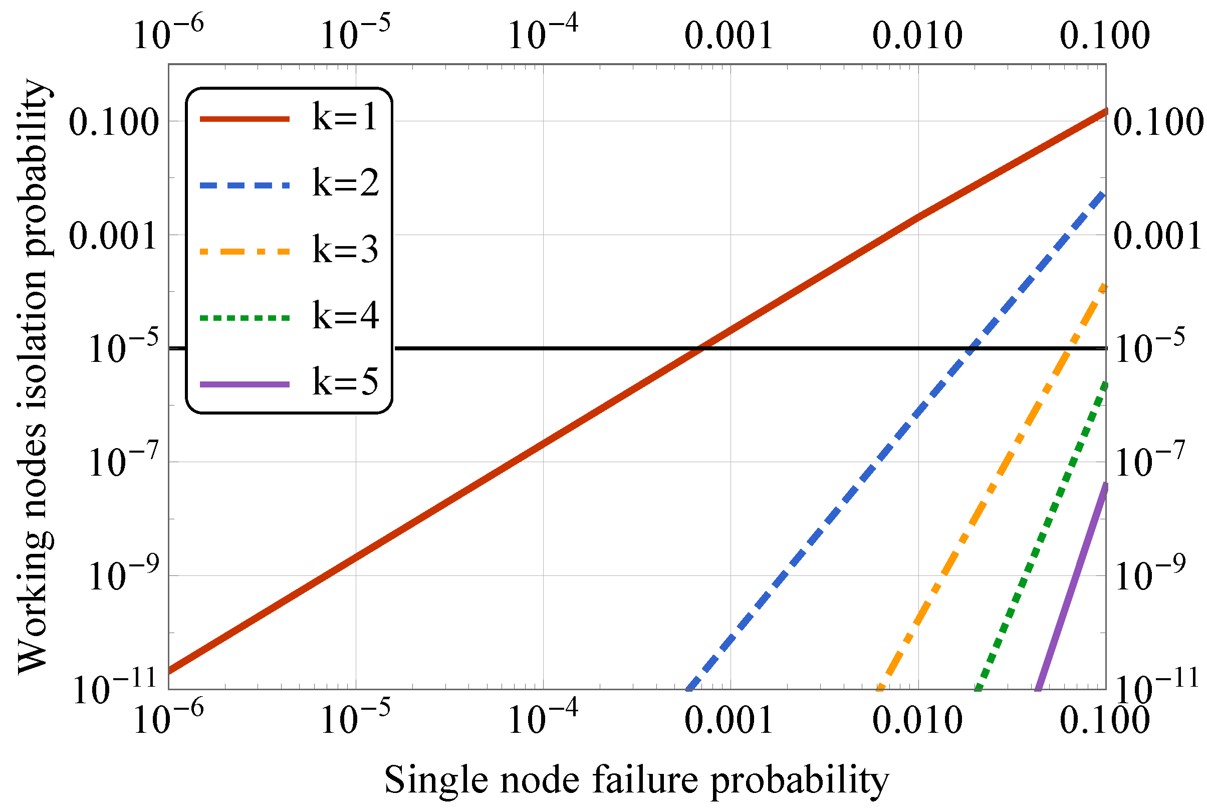
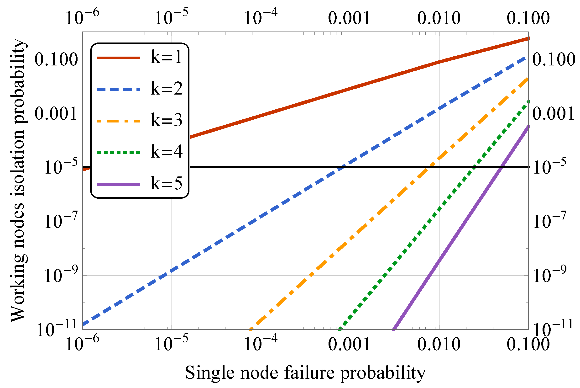
5. Selected Numerical Results
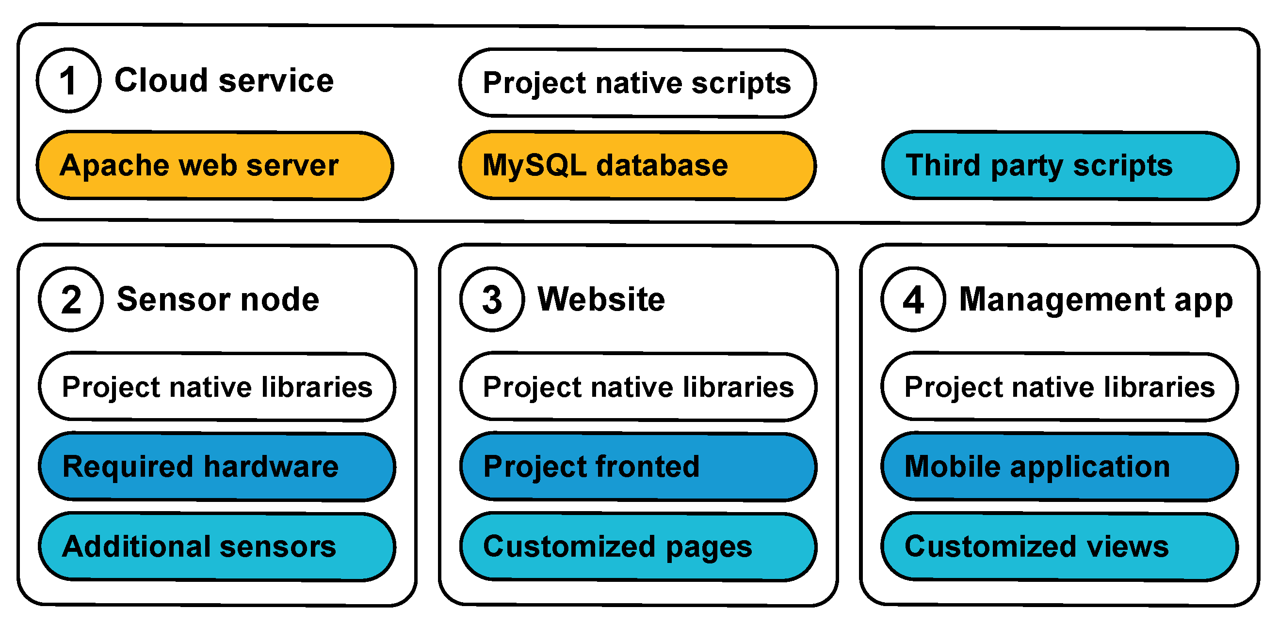
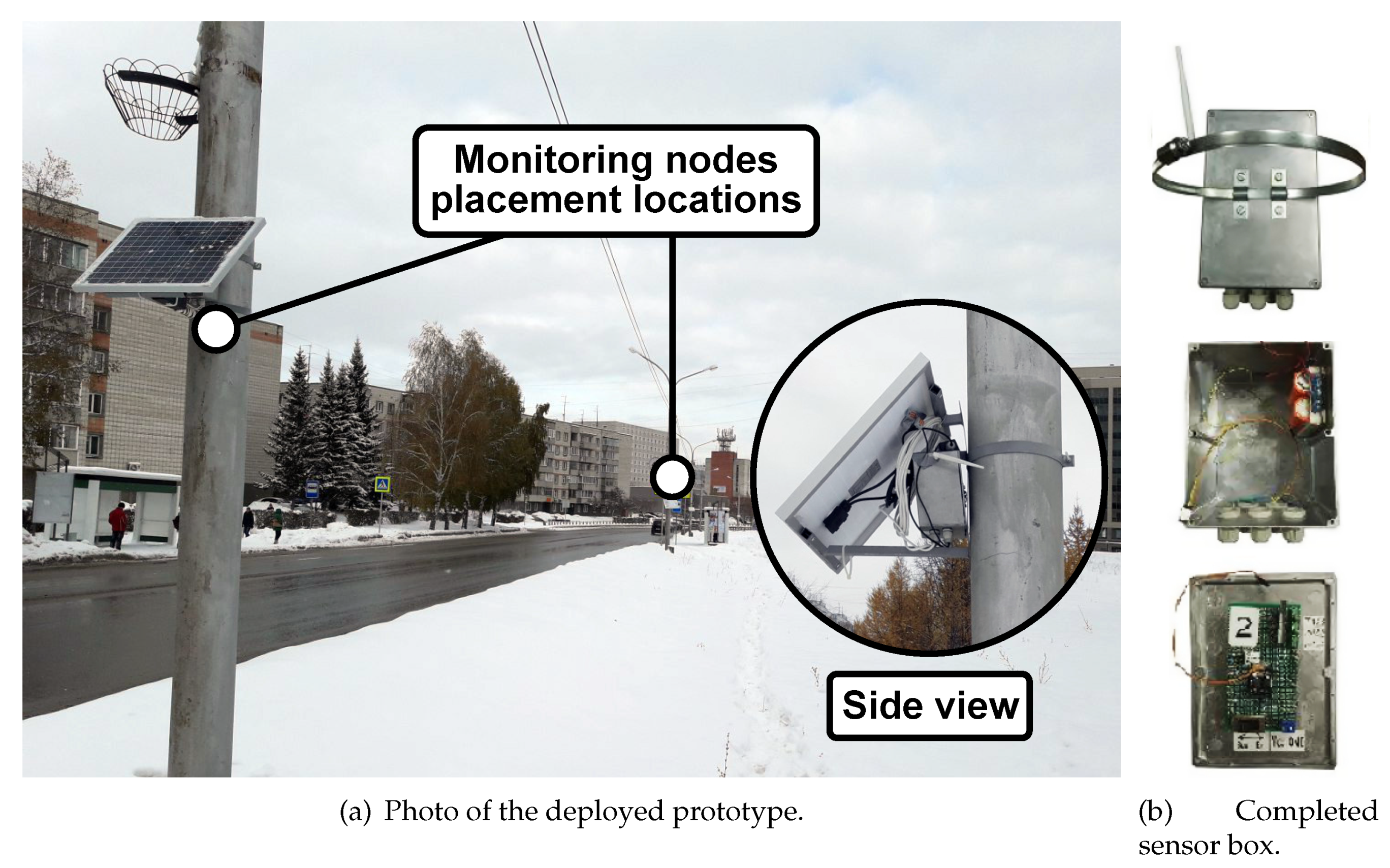
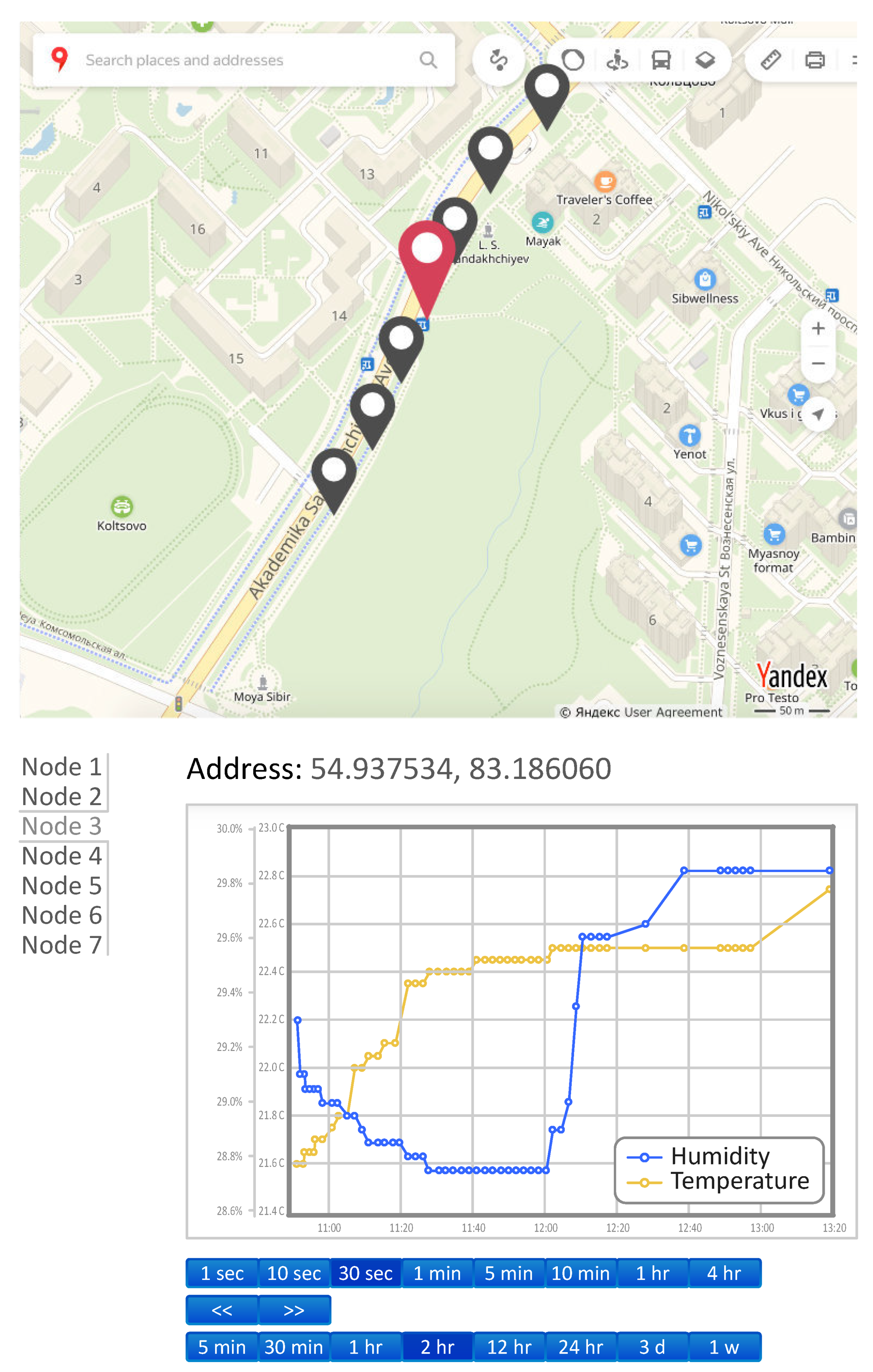
6. Prototyping Aspects
- Access sharing;
- Routing between devices;
- Remote access; and
- Setting up the network credentials, and other tasks.
- To register in the cloud and generate its encryption key. In this case, the generated encryption key is stored only on the user smartphone but could be sent to the cloud.
- To perform node initialization.
- To interact with already initialized devices directly when they are in the communication range of the selected wireless technology.
- To specify access credentials of known APs and distribute those to all related devices.
- To interact with the devices via the infrastructure network. In this case, all transferred data are protected with end-to-end encryption between the smartphone and the node.
7. Conclusions
Author Contributions
Funding
Conflicts of Interest
Abbreviations
| AP | Access Point |
| API | Application Programming Interface |
| CPS | Cyber-Physical System |
| CU | Control Unit |
| DPU | Data Processing Unit |
| GIS | Geographical Information Systems |
| GUI | Graphical User Interface |
| HTML | Hypertext Markup Language |
| ID | Identifier |
| IEEE | Institute of Electrical and Electronics Engineers |
| IIoT | Industrial Internet of Things |
| IoT | Internet of Things |
| IP (Code) | International Protection Marking |
| JSON | JavaScript Object Notation |
| LEAP | Lightweight Extensible Authentication Protocol |
| M2M | Machine-to-Machine Communications |
| MK | Master Key |
| NASA | The National Aeronautics and Space Administration |
| NFC | Near Field Communications |
| PCU | Power Control Unit |
| PHP | Hypertext Preprocessor |
| PKI | Public Key Infrastructure |
| REST | Representational State Transfer |
| RFID | Radio-frequency Identification |
| SQL | Structured Query Language |
| UART | Universal Asynchronous Receiver/Transmitter |
| UWB | Ultra-wideband Radio Technology |
| WiFi | Wireless Fidelity |
| WSN | Wireless Sensor Network |
References
- NASA’s Jet Propulsion Laboratory. Facts|The Effects of Climate Change. 2019. Available online: https://climate.nasa.gov/effects/ (accessed on 14 December 2019).
- Pritchard, H.; Ligtenberg, S.; Fricker, H.; Vaughan, D.; Van den Broeke, M.; Padman, L. Antarctic ice-sheet loss driven by basal melting of ice shelves. Nature 2012, 484, 502. [Google Scholar] [CrossRef] [PubMed]
- Kim, H.Y.; Park, S.Y.; Yoo, S.H. Public acceptability of introducing a biogas mandate in Korea: A contingent valuation study. Sustainability 2016, 8, 1087. [Google Scholar] [CrossRef]
- European Commission. Causes of Climate Change. 2019. Available online: https://ec.europa.eu/clima/change/causes_en (accessed on 14 December 2019).
- Zhu, C.; Rodrigues, J.J.; Leung, V.C.; Shu, L.; Yang, L.T. Trust-based Communication for the Industrial Internet of Things. IEEE Commun. Mag. 2018, 56, 16–22. [Google Scholar] [CrossRef]
- Mozny, R.; Masek, P.; Stusek, M.; Zeman, K.; Ometov, A.; Hosek, J. On the Performance of Narrow-band Internet of Things (NB-IoT) for Delay-tolerant Services. In Proceedings of the 42nd International Conference on Telecommunications and Signal Processing (TSP), Budapest, Hungary, 1–3 July 2019; pp. 637–642. [Google Scholar]
- Hosek, J.; Masek, P.; Andreev, S.; Galinina, O.; Ometov, A.; Kropfl, F.; Wiedermann, W.; Koucheryavy, Y. A SyMPHOnY of integrated IoT businesses: Closing the gap between availability and adoption. IEEE Commun. Mag. 2017, 55, 156–164. [Google Scholar] [CrossRef]
- Lee, H.C.; Ke, K.H. Monitoring of large-area IoT sensors using a LoRa wireless mesh network system: Design and evaluation. IEEE Trans. Instrum. Meas. 2018, 67, 2177–2187. [Google Scholar] [CrossRef]
- Ometov, A.; Daneshfar, N.; Hazmi, A.; Andreev, S.; Carpio, L.F.D.; Amin, P.; Torsner, J.; Koucheryavy, Y.; Valkama, M. System-level Analysis of IEEE 802.11ah Technology for Unsaturated MTC Traffic. Int. J. Sens. Netw. 2018, 26, 269–282. [Google Scholar] [CrossRef]
- Sisinni, E.; Saifullah, A.; Han, S.; Jennehag, U.; Gidlund, M. Industrial Internet of Things: Challenges, Opportunities, and Directions. IEEE Trans. Ind. Inform. 2018, 14, 4724–4734. [Google Scholar] [CrossRef]
- Masek, P.; Hudec, D.; Krejci, J.; Ometov, A.; Hosek, J.; Samouylov, K. Communication Capabilities of Wireless M-BUS: Remote Metering Within SmartGrid Infrastructure. In International Conference on Distributed Computer and Communication Networks; Springer: Berlin/Heidelberg, Germany, 2018; pp. 31–42. [Google Scholar]
- Talavera, J.M.; Tobón, L.E.; Gómez, J.A.; Culman, M.A.; Aranda, J.M.; Parra, D.T.; Quiroz, L.A.; Hoyos, A.; Garreta, L.E. Review of IoT Applications in Agro-industrial and Environmental Fields. Comput. Electron. Agric. 2017, 142, 283–297. [Google Scholar] [CrossRef]
- Sadeghi, A.R.; Wachsmann, C.; Waidner, M. Security and Privacy Challenges in Industrial Internet of Things. In Proceedings of the 2015 52nd ACM/EDAC/IEEE Design Automation Conference (DAC), San Francisco, CA, USA, 8–12 June 2015; pp. 1–6. [Google Scholar]
- Frustaci, M.; Pace, P.; Aloi, G.; Fortino, G. Evaluating Critical Security Issues of the IoT World: Present and Future Challenges. IEEE Internet Things J. 2018, 5, 2483–2495. [Google Scholar] [CrossRef]
- Ullah, I.; Ul Amin, N.; Zareei, M.; Zeb, A.; Khattak, H.; Khan, A.; Goudarzi, S. A Lightweight and Provable Secured Certificateless Signcryption Approach for Crowdsourced IIoT Applications. Symmetry 2019, 11, 1386. [Google Scholar] [CrossRef]
- Nesteruk, S.; Bezzateev, S. Location-Based Protocol for the Pairwise Authentication in the Networks without Infrastructure. In Proceedings of the 22nd Conference of Open Innovations Association (FRUCT), Jyvaskyla, Finland, 15–18 May 2018; pp. 190–197. [Google Scholar]
- Kannengießer, N.; Lins, S.; Dehling, T.; Sunyaev, A. What Does Not Fit Can be Made to Fit! Trade-Offs in Distributed Ledger Technology Designs. Trade-Offs Distrib. Ledger Technol. Des. 2019. [Google Scholar] [CrossRef]
- Lamberti, R.; Fries, C.; Lücking, M.; Manke, R.; Kannengießer, N.; Sturm, B.; Komarov, M.M.; Stork, W.; Sunyaev, A. An Open Multimodal Mobility Platform Based on Distributed Ledger Technology. In Internet of Things, Smart Spaces, and Next Generation Networks and Systems; Springer: Berlin/Heidelberg, Germany, 2019; pp. 41–52. [Google Scholar]
- Vermesan, O.; Friess, P. Internet of Things: Converging Technologies for Smart Environments and Integrated Ecosystems; River Publishers: Aalborg, Denmark, 2013. [Google Scholar]
- Masek, P.; Masek, J.; Frantik, P.; Fujdiak, R.; Ometov, A.; Hosek, J.; Andreev, S.; Mlynek, P.; Misurec, J. A Harmonized Perspective on Transportation Management in Smart Cities: The Novel IoT-drive Eenvironment for Road Traffic Modeling. Sensors 2016, 16, 1872. [Google Scholar] [CrossRef] [PubMed]
- Balageas, D.; Fritzen, C.P.; Güemes, A. Structural Health Monitoring; John Wiley & Sons: Hoboken, NJ, USA, 2010; Volume 90. [Google Scholar]
- Pun, C.S.J.; So, C.W.; Leung, W.Y.; Wong, C.F. Contributions of artificial lighting sources on light pollution in Hong Kong measured through a night sky brightness monitoring network. J. Quant. Spectrosc. Radiat. Transf. 2014, 139, 90–108. [Google Scholar] [CrossRef]
- Hannan, M.; Arebey, M.; Begum, R.A.; Basri, H. Radio Frequency Identification (RFID) and communication technologies for solid waste bin and truck monitoring system. Waste Manag. 2011, 31, 2406–2413. [Google Scholar] [CrossRef] [PubMed]
- Segura-Garcia, J.; Felici-Castell, S.; Perez-Solano, J.J.; Cobos, M.; Navarro, J.M. Low-cost alternatives for urban noise nuisance monitoring using wireless sensor networks. IEEE Sens. J. 2014, 15, 836–844. [Google Scholar] [CrossRef]
- Shaban, K.B.; Kadri, A.; Rezk, E. Urban air pollution monitoring system with forecasting models. IEEE Sens. J. 2016, 16, 2598–2606. [Google Scholar] [CrossRef]
- Wang, S.; Wan, J.; Li, D.; Zhang, C. Implementing Smart Factory of Industrie 4.0: An Outlook. Int. J. Distrib. Sens. Netw. 2016, 12, 3159805. [Google Scholar] [CrossRef]
- Karami, M.; McMorrow, G.V.; Wang, L. Continuous monitoring of indoor environmental quality using an Arduino-based data acquisition system. J. Build. Eng. 2018, 19, 412–419. [Google Scholar] [CrossRef]
- Risteska Stojkoska, B.; Popovska Avramova, A.; Chatzimisios, P. Application of wireless sensor networks for indoor temperature regulation. Int. J. Distrib. Sens. Netw. 2014, 10, 502419. [Google Scholar] [CrossRef]
- Cao, T.; Thompson, J.E. Personal monitoring of ozone exposure: A fully portable device for under $150 USD cost. Sens. Actuators B Chem. 2016, 224, 936–943. [Google Scholar] [CrossRef]
- Lohan, E.; Torres-Sospedra, J.; Leppäkoski, H.; Richter, P.; Peng, Z.; Huerta, J. Wi-Fi crowdsourced fingerprinting dataset for indoor positioning. Data 2017, 2, 32. [Google Scholar] [CrossRef]
- Krivtsova, I.; Lebedev, I.; Sukhoparov, M.; Bazhayev, N.; Zikratov, I.; Ometov, A.; Andreev, S.; Masek, P.; Fujdiak, R.; Hosek, J. Implementing a Broadcast Storm Attack on a Mission-critical Wireless Sensor Network. In Wired/Wireless Internet Communications; Springer: Berlin/Heidelberg, Germany, 2016; pp. 297–308. [Google Scholar]
- Felemban, E. Advanced border intrusion detection and surveillance using wireless sensor network technology. Int. J. Commun. Netw. Syst. Sci. 2013, 6, 251. [Google Scholar] [CrossRef]
- Santos, A.; Younis, M. A sensor network for non-intrusive and efficient leak detection in long pipelines. In Proceedings of the IFIP Wireless Days (WD), Niagara Falls, ON, Canada, 10–12 October 2011; pp. 1–6. [Google Scholar]
- Makeenkov, A.; Lapitskiy, I.; Somov, A.; Baranov, A. Flammable gases and vapors of flammable liquids: Monitoring with infrared sensor node. Sens. Actuators B Chem. 2015, 209, 1102–1107. [Google Scholar] [CrossRef]
- Gomaa, R.; Adly, I.; Sharshar, K.; Safwat, A.; Ragai, H. ZigBee wireless sensor network for radiation monitoring at nuclear facilities. In Proceedings of the 6th Joint IFIP Wireless and Mobile Networking Conference (WMNC), Dubai, United Arab Emirates, 23–25 April 2013; pp. 1–4. [Google Scholar]
- Henriques, V.; Malekian, R. Mine safety system using wireless sensor network. IEEE Access 2016, 4, 3511–3521. [Google Scholar] [CrossRef]
- Dlodlo, N.; Kalezhi, J. The Internet of Things in Agriculture for Sustainable Rural Development. In Proceedings of the International Conference on Emerging Trends in Networks and Computer Communications (ETNCC), Windhoek, Namibia, 17–20 May 2015; pp. 13–18. [Google Scholar]
- Aziz, N.A.A.; Aziz, K.A. Managing disaster with wireless sensor networks. In Proceedings of the 13th International Conference on Advanced Communication Technology (ICACT2011), Seoul, Korea, 13–16 February 2011; pp. 202–207. [Google Scholar]
- Faulkner, M.; Olson, M.; Chandy, R.; Krause, J.; Chandy, K.M.; Krause, A. The next big one: Detecting earthquakes and other rare events from community-based sensors. In Proceedings of the 10th ACM/IEEE International Conference on Information Processing in Sensor Networks, Chicago, IL, USA, 12–14 April 2011; pp. 13–24. [Google Scholar]
- Aslan, Y.E.; Korpeoglu, I.; Ulusoy, Ö. A framework for use of wireless sensor networks in forest fire detection and monitoring. Comput. Environ. Urban Syst. 2012, 36, 614–625. [Google Scholar] [CrossRef]
- Aqeel-ur-Rehma; Abbasi, A.Z.; Islam, N.; Shaikh, Z.A. A review of wireless sensors and networks’ applications in agriculture. Comput. Stand. Interfaces 2014, 36, 263–270. [Google Scholar] [CrossRef]
- Chaudhary, D.; Nayse, S.; Waghmare, L. Application of wireless sensor networks for greenhouse parameter control in precision agriculture. Int. J. Wirel. Mob. Netw. 2011, 3, 140–149. [Google Scholar] [CrossRef]
- Muller, C.L.; Chapman, L.; Grimmond, C.; Young, D.T.; Cai, X.M. Toward a standardized metadata protocol for urban meteorological networks. Bull. Am. Meteorol. Soc. 2013, 94, 1161–1185. [Google Scholar] [CrossRef]
- Kim, S.H.; Kim, D.H.; Park, H.D. Animal situation tracking service using RFID, GPS, and sensors. In Proceedings of the Second International Conference on Computer and Network Technology, Bangkok, Thailand, 23–25 April 2010; pp. 153–156. [Google Scholar]
- Medela, A.; Cendón, B.; González, L.; Crespo, R.; Nevares, I. IoT multiplatform networking to monitor and control wineries and vineyards. In Proceedings of the Future Network & Mobile Summit, Lisboa, Portugal, 3–5 July 2013; pp. 1–10. [Google Scholar]
- Hwang, J.; Yoe, H. Study of the ubiquitous hog farm system using wireless sensor networks for environmental monitoring and facilities control. Sensors 2010, 10, 10752–10777. [Google Scholar] [CrossRef]
- Casas, O.; López, M.; Quílez, M.; Martinez-Farre, X.; Hornero, G.; Rovira, C.; Pinilla, M.R.; Ramos, P.M.; Borges, B.; Marques, H.; et al. Wireless sensor network for smart composting monitoring and control. Measurement 2014, 47, 483–495. [Google Scholar] [CrossRef]
- Singh, M.; Rajan, M.; Shivraj, V.; Balamuralidhar, P. Secure MQTT for Internet of Things (IoT). In Proceedings of the Fifth International Conference on Communication Systems and Network Technologies, Gwalior, India, 4–6 April 2015; pp. 746–751. [Google Scholar]
- Zakaria, O.M.; Hashim, A.H.A.; Hassan, W.H.; Khalifa, O.O.; Azram, M.; Goudarzi, S.; Jivanadham, L.B.; Zareei, M. State-Aware Re-configuration Model for Multi-Radio Wireless Mesh Networks. KSII Trans. Internet Inf. Syst. 2017, 11. [Google Scholar] [CrossRef]
- Ahmed, A.; Bakar, K.A.; Channa, M.I.; Haseeb, K.; Khan, A.W. A survey on trust based detection and isolation of malicious nodes in ad-hoc and sensor networks. Front. Comput. Sci. 2015, 9, 280–296. [Google Scholar] [CrossRef]
- Pathan, A.S.K. Security of Self-Organizing Networks: MANET, WSN, WMN, VANET; CRC Press: Boca Raton, FL, USA, 2016. [Google Scholar]
- Ometov, A.; Zhidanov, K.; Bezzateev, S.; Florea, R.; Andreev, S.; Koucheryavy, Y. Securing Network-Assisted Direct Communication: The Case of Unreliable Cellular Connectivity. In Proceedings of the IEEE 14th International Conference on Trust, Security and Privacy in Computing and Communications (TrustCom), Helsinki, Finland, 20–22 August 2015. [Google Scholar]
- Lee, J.; Stinson, D.R. Deterministic Key Predistribution Schemes for Distributed Sensor Networks. In International Workshop on Selected Areas in Cryptography; Springer: Berlin/Heidelberg, Germany, 2004; pp. 294–307. [Google Scholar]
- Zhu, S.; Setia, S.; Jajodia, S. LEAP+: Efficient Security Mechanisms for Large-scale Distributed Sensor Networks. ACM Trans. Sens. Netw. (TOSN) 2006, 2, 500–528. [Google Scholar] [CrossRef]
- Jang, J.; Kwon, T.; Song, J. A Time-based Key Management Protocol for Wireless Sensor Networks. In International Conference on Information Security Practice and Experience; Springer: Berlin/Heidelberg, Germany, 2007; pp. 314–328. [Google Scholar]
- Zhang, W.; Tran, M.; Zhu, S.; Cao, G. A Random Perturbation-based Scheme for Pairwise Key Establishment in Sensor Networks. In Proceedings of the 8th ACM International Symposium on Mobile Ad Hoc Networking and Computing, Montreal, QC, Canada, 9–14 September 2007; pp. 90–99. [Google Scholar]
- Lohan, E.S.; Koivisto, M.; Galinina, O.; Andreev, S.; Tolli, A.; Destino, G.; Costa, M.; Leppanen, K.; Koucheryavy, Y.; Valkama, M. Benefits of Positioning-Aided Communication Technology in High-Frequency Industrial IoT. IEEE Commun. Mag. 2018, 56, 142–148. [Google Scholar] [CrossRef]
- Nesteruk, S.; Kovalenko, V.; Bezzateev, S. A Survey on Localized Authentication Protocols for Wireless Sensor Networks. In Proceedings of the Wave Electronics and its Application in Information and Telecommunication Systems (WECONF), St. Petersburg, Russia, 26–30 November 2018; pp. 1–7. [Google Scholar]
- Furth, P.G.; Rahbee, A.B. Optimal bus stop spacing through dynamic programming and geographic modeling. Transp. Res. Rec. 2000, 1731, 15–22. [Google Scholar] [CrossRef]
- Traverso, M.; Donatello, S.; Moons, H.; Rodriguez, R.; Quintero, M.G.C.; JRC, W.O.; Van Tichelen, P.; Van, V.; Hoof, T.G.V. Revision of the EU Green Public Procurement Criteria for Street Lighting and Traffic Signals; Publications Office of the European Union: Luxembourg, 2017. [Google Scholar]
- Jelicic, V.; Magno, M.; Brunelli, D.; Paci, G.; Benini, L. Context-adaptive multimodal wireless sensor network for energy-efficient gas monitoring. IEEE Sens. J. 2012, 13, 328–338. [Google Scholar] [CrossRef]
- Coleri, S.; Cheung, S.Y.; Varaiya, P. Sensor networks for monitoring traffic. In Proceedings of the Allerton Conference on Communication, Control and Computing, Monticello, IL, USA, 29 September–1 October 2004; pp. 32–40. [Google Scholar]
- Devos, M.; Ometov, A.; Mäkitalo, N.; Aaltonen, T.; Andreev, S.; Koucheryavy, Y. D2D communications for mobile devices: Technology overview and prototype implementation. In Proceedings of the 8th International Congress on Ultra Modern Telecommunications and Control Systems and Workshops (ICUMT), Lisbon, Portugal, 18–20 October 2016; pp. 124–129. [Google Scholar]
- Atmel. ATmega328P–8-bit AVR Microcontroller with 32K Bytes In-System Programmable Flash. 2019. Available online: http://ww1.microchip.com/downloads/en/DeviceDoc/Atmel-7810-Automotive-Microcontrollers-ATmega328P_Datasheet.pdf (accessed on 14 December 2019).
- ESPRESSIF. ESP8266—Low-Power, Highly-Integrated Wi-Fi Solution. 2019. Available online: https://www.espressif.com/en/products/hardware/esp8266ex/overview (accessed on 14 December 2019).
- Citrix. Resurrecting Duckling: A Model for Securing IoT Devices. 2019. Available online: https://www.citrix.com/blogs/2015/04/20/resurrecting-duckling-a-model-for-securing-iot-devices/ (accessed on 14 December 2019).
- Krentz, K.F.; Wunder, G. 6DOKU: Towards Secure Over-the-Air Preloading of 6LOWPAN Nodes Using PHY Key Generation. In Proceedings of the European Conference on Smart Objects, Systems and Technologies, Aachen, Germany, 16–17 July 2015; pp. 1–11. [Google Scholar]
- Zareei, M.; Vargas-Rosales, C.; Anisi, M.H.; Musavian, L.; Villalpando-Hernandez, R.; Goudarzi, S.; Mohamed, E.M. Enhancing the Performance of Energy Harvesting Sensor Networks for Environmental Monitoring Applications. Energies 2019, 12, 2794. [Google Scholar] [CrossRef]
- Galinina, O.; Turlikov, A.; Hosek, J.; Andreev, S. Energy efficient power allocation in a multi-radio mobile device with wireless energy harvesting. In Proceedings of the 6th International Congress on Ultra Modern Telecommunications and Control Systems and Workshops (ICUMT), St. Petersburg, Russia, 6–8 October 2014; pp. 380–385. [Google Scholar]
- Albic. S-8205A/B Series: Battery Protection IC for 4-Series or 5-Series Cell Pack. 2019. Available online: https://www.ablic.com/en/doc/datasheet/battery_protection/S8205A_B_E.pdf (accessed on 14 December 2019).
- IOLA and Ole Laursen. Attractive JavaScript Plotting for jQuery. 2014. Available online: https://www.flotcharts.org (accessed on 14 December 2019).
- Yandex. Maps API–JavaScript API. 2019. Available online: https://tech.yandex.com/maps/jsapi/ (accessed on 14 December 2019).


| Notation | Description |
|---|---|
| k | Number of sensors |
| Indexes | |
| Master Key | |
| ith sensor node unique identifier | |
| One-way function | |
| Auxiliary key for ith and jth nodes | |
| lifetime period after the initialization phase | |
| Subset of nodes that have pairwise connection with ith node | |
| Number of nodes in | |
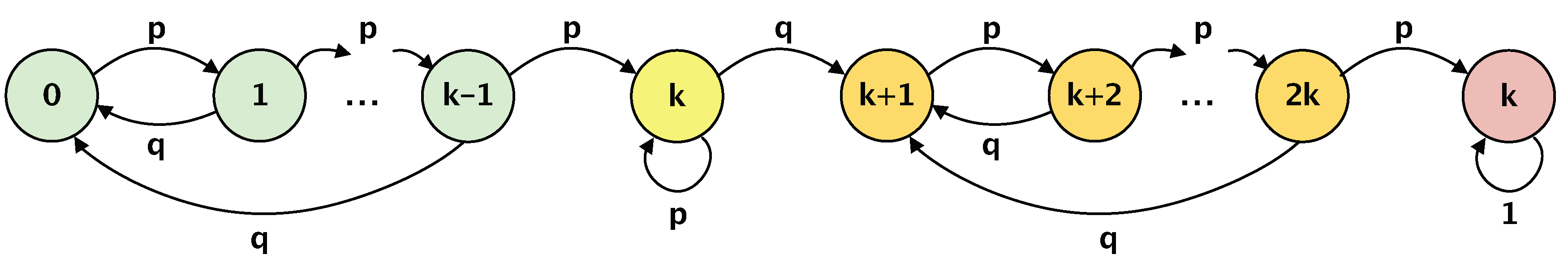
| p | Single node failure probability () |
| S | State space of the Markov chain |
| Transition probability from state i to state j |
| State | 0 | 1 | ⋯ | k− 1 | k | k + 1 | ⋯ | 2k | 2k + 1 |
|---|---|---|---|---|---|---|---|---|---|
| 0 | q | p | 0 | ⋯ | ⋯ | ⋯ | ⋯ | ⋯ | 0 |
| 1 | q | 0 | p | 0 | ⋯ | ⋯ | ⋯ | ⋯ | 0 |
| ⋮ | ⋮ | ⋱ | ⋮ | ||||||
| k− 1 | q | 0 | ⋯ | 0 | p | 0 | ⋯ | ⋯ | 0 |
| k | 0 | ⋯ | ⋯ | 0 | p | q | 0 | ⋯ | 0 |
| k + 1 | 0 | ⋯ | ⋯ | ⋯ | 0 | q | p | 0 | 0 |
| ⋮ | ⋮ | ⋮ | ⋱ | ⋮ | |||||
| 2k | 0 | ⋯ | ⋯ | ⋯ | 0 | q | 0 | 0 | p |
| 2k + 1 | 0 | ⋯ | ⋯ | ⋯ | ⋯ | 0 | ⋯ | 0 | 1 |
| Component | Type | Description |
|---|---|---|
| Atmel ATmega328P | Data processing and control | Micro-controller is dedicated to the system operation, which holds the functionality of the data processing unit (DPU) and control unit (CU) [64]. |
| Data Processing Unit | Data processing and control | DPU is implemented in ATmega328P and performs the functions of preprocessing information received from sensors for secure and reliable transmission to the server unit. Data pre-processing is carried out in accordance with the previously developed and used Galouis platform. |
| Control Unit | Data processing and control | CU is implemented in ATmega328P and ensures the operation of the radio module and the DPU, determining their operation in various modes in accordance with the Galois platform used. Besides, CU regulates the mode of operation of the sensors, ensuring efficient energy consumption in the respective modes of the system (simplex, half-duplex, and full-duplex), and also allows the interaction through the radio module with the mobile device during the initialization of the sensor and the end of its operation. |
| ESP8266 radio module | Communications | Provides data transfer via IEEE 802.11n protocol [65]. The radio module receives data from DPU according to the control commands from the CU and transfers it to the networking part of the system or the nearest sensor located in its communications range. Note, in the duplex mode of operation, the radio module relays the data received from the sensors located in its coverage area according to the commands received from the control unit. |
| Power Control Unit (PCU) | Power supply | Provides safe switching between available power sources in order to realize the uninterrupted power supply of the sensor, regardless of weather conditions and the state of available power sources. As a baseline element, the system utilizes the SII-8205A board [70]. |
| Battery | Power supply | Li-ion, 6800 mAh, 3.7 V. |
| Solar panel | Power supply | 45 W, 12 V (optional). |
| Power source | Power supply | 12 V, 2 A (optional). |
© 2019 by the authors. Licensee MDPI, Basel, Switzerland. This article is an open access article distributed under the terms and conditions of the Creative Commons Attribution (CC BY) license (http://creativecommons.org/licenses/by/4.0/).
Share and Cite
Ometov, A.; Bezzateev, S.; Voloshina, N.; Masek, P.; Komarov, M. Environmental Monitoring with Distributed Mesh Networks: An Overview and Practical Implementation Perspective for Urban Scenario. Sensors 2019, 19, 5548. https://doi.org/10.3390/s19245548
Ometov A, Bezzateev S, Voloshina N, Masek P, Komarov M. Environmental Monitoring with Distributed Mesh Networks: An Overview and Practical Implementation Perspective for Urban Scenario. Sensors. 2019; 19(24):5548. https://doi.org/10.3390/s19245548
Chicago/Turabian StyleOmetov, Aleksandr, Sergey Bezzateev, Natalia Voloshina, Pavel Masek, and Mikhail Komarov. 2019. "Environmental Monitoring with Distributed Mesh Networks: An Overview and Practical Implementation Perspective for Urban Scenario" Sensors 19, no. 24: 5548. https://doi.org/10.3390/s19245548
APA StyleOmetov, A., Bezzateev, S., Voloshina, N., Masek, P., & Komarov, M. (2019). Environmental Monitoring with Distributed Mesh Networks: An Overview and Practical Implementation Perspective for Urban Scenario. Sensors, 19(24), 5548. https://doi.org/10.3390/s19245548