Review

Corrosion Sensors for Structural Health Monitoring of Oil and Natural Gas Infrastructure: A Review

1
National Energy Technology Laboratory, Pittsburgh, PA 15236, USA
2
Leidos Research Support Team, Pittsburgh, PA 15236, USA
3
National Energy Technology Laboratory, Albany, OR 97321, USA
*
Authors to whom correspondence should be addressed.
Sensors 2019, 19(18), 3964; https://doi.org/10.3390/s19183964
Submission received: 19 August 2019 / Revised: 10 September 2019 / Accepted: 10 September 2019 / Published: 13 September 2019
(This article belongs to the Section Chemical Sensors)

Abstract

:
Corrosion has been a great concern in the oil and natural gas industry costing billions of dollars annually in the U.S. The ability to monitor corrosion online before structural integrity is compromised can have a significant impact on preventing catastrophic events resulting from corrosion. This article critically reviews conventional corrosion sensors and emerging sensor technologies in terms of sensing principles, sensor designs, advantages, and limitations. Conventional corrosion sensors encompass corrosion coupons, electrical resistance probes, electrochemical sensors, ultrasonic testing sensors, magnetic flux leakage sensors, electromagnetic sensors, and in-line inspection tools. Emerging sensor technologies highlight optical fiber sensors (point, quasi-distributed, distributed) and passive wireless sensors such as passive radio-frequency identification sensors and surface acoustic wave sensors. Emerging sensors show great potential in continuous real-time in-situ monitoring of oil and natural gas infrastructure. Distributed chemical sensing is emphasized based on recent studies as a promising method to detect early corrosion onset and monitor corrosive environments for corrosion mitigation management. Additionally, challenges are discussed including durability and stability in extreme and harsh conditions such as high temperature high pressure in subsurface wellbores.

1. Introduction

1.1. Corrosion Problems in Oil and Natural Gas Industry

Corrosion has been a great concern in the oil and natural gas (O&G) industry because it adversely affects infrastructure in exploration, production, processing, and transport with significant economic costs and safety considerations [1,2,3]. For domestic O&G exploration and production in the U.S., direct corrosion costs were determined to be about $1.4 billion annually, according to a study released in 2002, with $589 million attributed to surface piping and facility costs, $463 million to downhole tubing expenses, and $320 million to capital expenditures related to corrosion [4]. There are more than 528,000 km (328,000 miles) of natural gas transmission and gathering pipelines, and 119,000 km (74,000 miles) of crude oil transmission and gathering pipelines. The estimated corrosion-related cost is about $5.8 billion annually to monitor, replace, and maintain these assets [4]. According to the Pipeline and Hazardous Materials Safety Administration (PHMSA) database, corrosion has caused ~25% of the natural gas transmission and gathering pipeline incidents over the last 30 years, and 61% out of corrosion caused incidents were due to internal corrosion [5,6]. It has been challenging to monitor internal corrosion effectively as the inside of pipeline is not readily accessible during regular maintenance and inspection. Moreover, corrosion can occur at some random locations inside and outside pipelines over thousands of miles. Therefore, it is of crucial importance to locate corrosion events along the long-distance infrastructure for effective real-time corrosion monitoring.
Corrosion is an electrochemical process involving oxidation of metallic materials, causing mass loss and structural deterioration. An electrochemical system is essentially composed of an anode, a cathode, and an electrolyte. The anode is the corroding site on the steel, Reaction 1, and the cathode is where the reduction reaction occurs. The electrolyte is usually an aqueous solution with dissolved salts (e.g., NaCl) and corrosive species, and it connects the anode and cathode through ionic conductivity so that the electron transfer can be balanced between the two electrodes. In the anaerobic subsurface wellbores, ubiquitous acidic gases CO2 and H2S can dissolve into the electrolyte, reduce the pH and promote cathodic reactions through Reactions 2–4, accelerating corrosion process [7,8,9,10,11,12]. Although most downhole hydrocarbon reservoirs have virtually no dissolved oxygen in the fluids, the presence of dissolved O2 in drilling fluid can be a major concern for corrosion of drill pipelines and well casing as O2 is a strong oxidant even at ppb or ppm levels, Reaction 5 [2,13,14,15].
Anode:  Fe → Fe2+ + 2 e               
Cathode:  2 CO2(aq) + 2 H2O(l) + 2 e → H2(g) + 2 HCO3(aq)
2 H2S(aq) + 2 e → H2(g) + 2 HS(aq)
2 H+(aq) + 2 e → H2(g)
0.5 O2(aq) + H2O(l) + 2 e → 2 OH(aq)
Besides mass loss due to electrochemical reactions, corrosion combined with mechanical effects can cause undesirable cracking and resulted catastrophic failures during oil and gas exploration, drilling, production, processing, and transport due to hydrogen induced cracking (HIC), sulfide stress cracking (SSC), stress corrosion cracking (SCC), and corrosion fatigue (CF) [16]. In this scenario, localized corrosion and pitting caused by H2S or Cl are particularly detrimental as a structural weak point is forming and can lead to cracking even when the external force is still within the rated mechanical stress. Microbes such as sulfate-reducing bacteria can also promote corrosion through producing H2S [15,17].
As a thermodynamically favorable process, corrosion is difficult to prevent, but can be kinetically controlled through corrosion mitigation and protection. Real-time in-situ monitoring of corrosion and associated parameters facilitates structural health evaluation and effective mitigation strategies, improving infrastructure security and reducing cost caused by catastrophic failures.

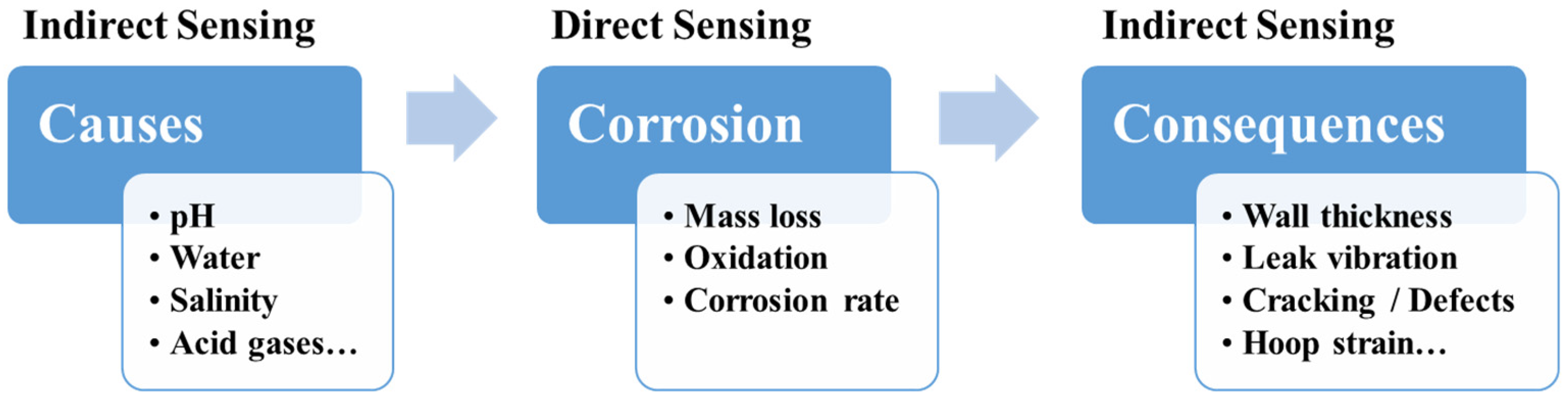
1.2. Functions and Categories of Corrosion Sensors

Implementing the best available corrosion prevention and control practices could save 25–30% of annual corrosion costs in the U.S. [4]. Effective corrosion monitoring bolsters the corrosion management systems and informs the decision-making entities. Monitoring corrosion rates enables service life evaluation and guides maintenance management. Carbon steel is commonly used in the O&G industry. For example, it is used for transmission pipes, drill pipes, and casing tubing [18], because of its mechanical properties and economic cost. However, it is prone to corrosion in service environments. Real-time corrosion monitoring and proper mitigation/maintenance are critical to maintaining the corrosion rate within an acceptable range to ensure that the infrastructures (e.g., pipes) meet the designed service life. In-situ and online monitoring of the early onset of corrosion also allows corrosion-related structural health monitoring (SHM) by recognizing early signs of structural risks, such as localized corrosion and micro-cracking, before structural failures and catastrophic events resulting from corrosion can occur. Furthermore, in-situ monitoring of corrosive environments facilitates corrosion mitigation strategies by identifying corrosion causes such as water, pH, Cl, CO2 and H2S. Besides monitoring corrosion rates, locating the corrosion spots or localized corrosion is also of significant value for further inspection and effective mitigation, especially for thousands of miles of transmission pipelines. Additionally, for the O&G industry applications, high durability and stability are required for corrosion sensors in extreme service conditions such as high temperature high pressure (HTHP) during drilling and production up to 200+ °C and 100 MPa [18].
Numerous corrosion sensor technologies have been developed based on different sensing principles for different types of corrosion. They can be generally categorized into two types: direct and indirect corrosion sensors [19]. As shown in Figure 1, the direct corrosion sensors monitor corrosion process/rates directly due to various corrosion causes and corrosive environments. The indirect corrosion sensors monitor corrosion through corrosion causes (e.g., low pH, water, CO2) or consequences (e.g., wall thickness changes, leak vibration, strain change). Comprehensive understanding of corrosion processes from causes to consequences inspires corrosion sensor development strategies by identifying parameters or phenomena of interest as sensing targets.
In this article, we briefly review and summarize conventional corrosion sensors which are well known, commonly used, and commercially available to provide the baseline and common practices in corrosion monitoring for the O&G industry. The main focus is emerging corrosion sensors including most recent technologies which are still in research and development (R&D) and technical transfer stages or only commercially available within the last two decades.

2. Conventional Corrosion Sensors

Conventional and commonly used corrosion sensors and SHM techniques in the O&G industry are discussed in this section. A review or summary on corrosion monitoring techniques in general or other areas is also available in References [19,20,21,22].

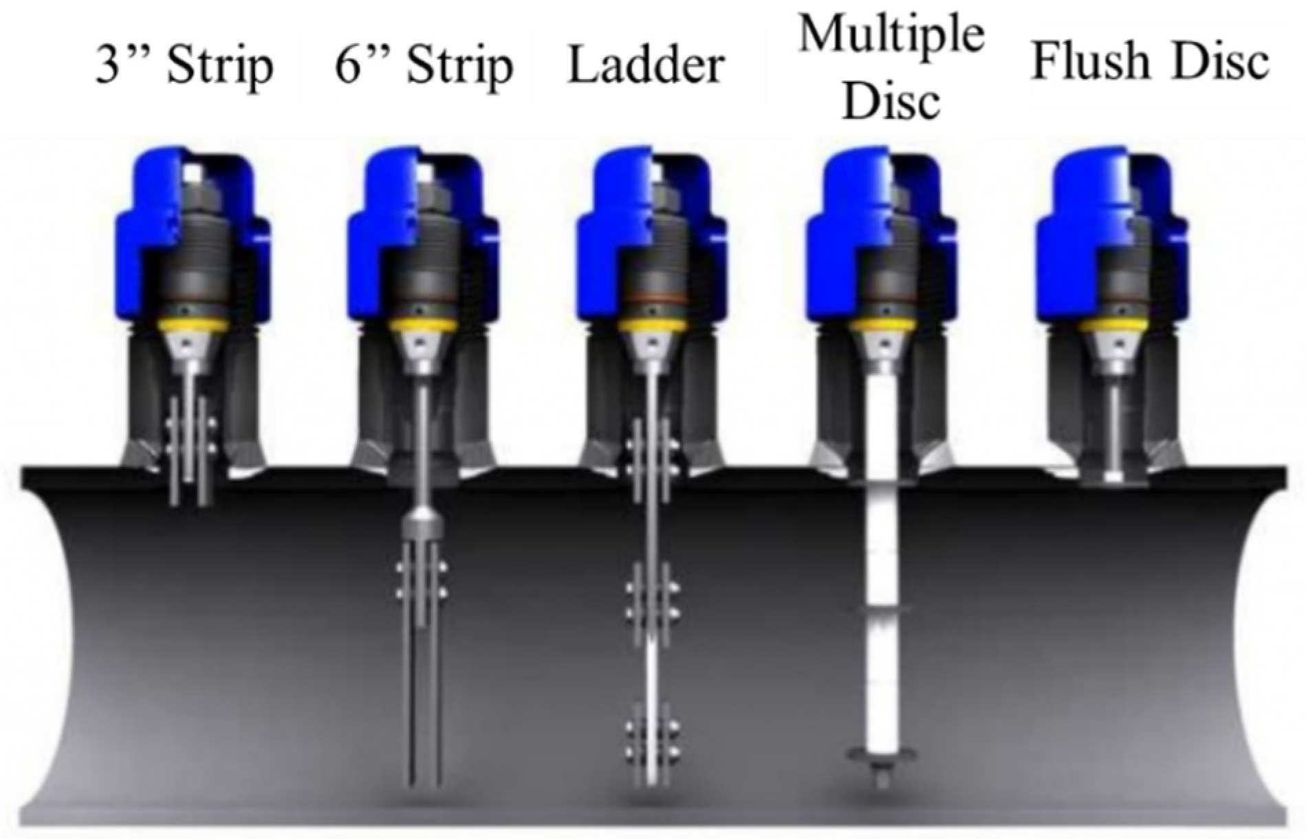
2.1. Corrosion Coupon

Corrosion coupon weight loss measurement is the most well-established and longest-used method in industry to measure corrosion rates. Weight loss measurement is still held as the gold standard to evaluate corrosion rates before a variety of corrosion monitoring technologies. The working principle is that a corrosion coupon, made of a material of interest with designed weight and shape, is installed and exposed to the corrosive environment for a duration of time and then retrieved for after-corrosion weight measurement and inspection on the corroded coupon [23]. The corrosion coupon method is commonly used because of its simple working principle, easy operation, and versatility in material and shape (Figure 2). However, installation, removal, and after-corrosion lab analysis of the coupons require an extended time period. The corrosion coupons only provide an average corrosion rate during a certain period without real-time information, and they are point sensors with limited sensing coverage for O&G infrastructures.

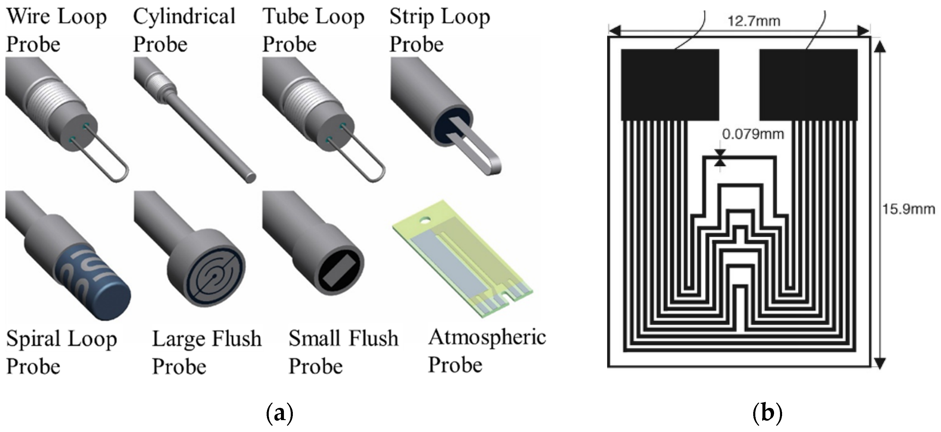
2.2. Electrical Resistance Probe

An electrical resistance (ER) probe is a commonly used approach for online corrosion rate monitoring with the capability of automatic and remote data logging in some advanced versions. It can be viewed as the “electrical” corrosion coupon that can be monitored in real-time via electrical resistance. Mass loss in the exposed metallic materials leads to an increase in electrical resistance. The exposed sensing element can be customized in material and shape for each specific application. ER probes work for both conductive media (e.g., water or oil systems with high water cuts) and non-conductive environments (e.g., oil, gas, and atmosphere). Some commercial ER probes are shown in Figure 3a [25]. A limitation of common ER probes is that they allow only the measurement of uniform corrosion, but Li et al. reported a multiple-line design of steel thin film ER probe which was sensitive to localized corrosion (Figure 3b) [26]. However, ER probes are still point sensors only capable of monitoring certain locations. An increase in sensing locations means an increase in total cost. Similar to corrosion coupons, installation locations need to be specifically picked to maximize the effectiveness of ER probes. Selecting locations is usually based on experience and some uncommon locations can be easily omitted even with significant corrosion. The electrical-based measurement enables electronic data collection and logging, but it also makes the ER probes prone to common electronic problems, which require regular maintenance and replacement. Importantly, electrical-based sensors must follow the intrinsic electrical safety requirements in the presence of flammable oil and natural gas.

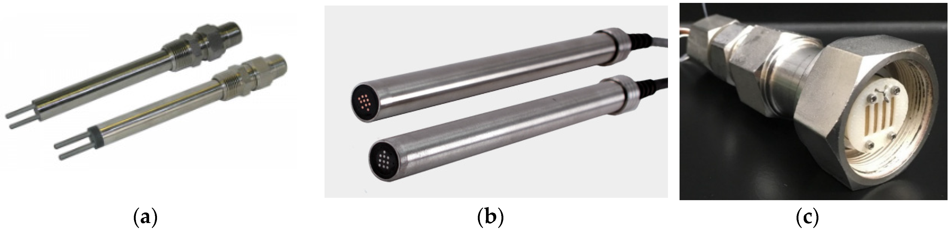
2.3. Electrochemical Sensors

Electrochemical sensors leverage the intrinsic electrochemical characteristics of corrosion and utilize electrochemical techniques such as galvanic current measurement, linear polarization resistance (LPR), electrochemical impedance spectroscopy (EIS), and electrochemical noise (EN) [22,27,28,29]. Advantages of electrochemical sensors include direct quantification of electrochemical corrosion rates and the capability of in-situ corrosion mechanism investigation with a variety of electrochemical techniques. LPR-based corrosion sensing is the most commercialized method among the electrochemical sensors because of relatively simple operation and data interpretation. For most of the commercial LPR probes (Figure 4a) [30], the electrodes (2 or 3) are often made of the same material instead of strictly following a classic electrochemical three-electrode system. The drawback of electrochemical sensors is that externally imposed potential or current may lead to an accelerated corrosion rate compared to the true value, so proper settings of electrochemical parameters (e.g., overpotential, scan rate, and Tafel slopes) and the electrode system design need to be carefully chosen. Additionally, the electrochemical sensors usually require an ion-conductive electrolyte, e.g., aqueous solutions, and they are not readily suitable for non-conductive environments without special modifications.
One commercially available electrochemical corrosion sensor to detect localized corrosion is based on the galvanic current in a coupled multi-electrode array [31,32], and the performance condition can reach 300 °C and 34.5 MPa (5000 psi) with proper packaging (Figure 4b) [33]. Also, water content and corrosion rates in simulated natural gas have been measured simultaneously using an ion-conducting membrane-based advanced electrochemical sensor (AES) (Figure 4c) [34,35]. Electrochemical sensors can also be designed to monitor pH and redox potentials in the environments.

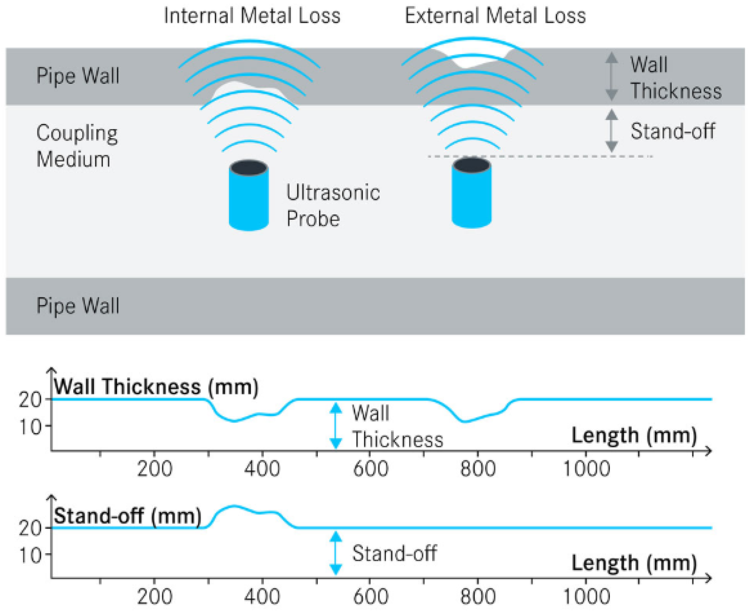
2.4. Ultrasonic Testing Sensor

Ultrasonic testing (UT) wall thickness measurement is one of the most popular nondestructive methods to monitor corrosion and structural health of pipes. A piezoelectric transducer generates high frequency (MHz) acoustic waves controlled through electric pulses, and these ultrasonic waves are emitted perpendicular to the pipe wall. The waves are bounced back by the external surface, inner surface, and geometric irregularities, which are received by the transducer. The tool measures the time interval between the arrivals of reflected echoes from inner and outer surfaces to calculate the wall thickness [36,37,38]. As shown in Figure 5 [39], the wall thickness information combined with the stand-off signal can differentiate the internal and external mass loss/flaw along the pipe. UT corrosion sensors have portable and fixed forms [29], and can also be integrated with in-line inspection devices. The UT method is capable of inspections with only one side accessible. The geometry resolution is related to the ultrasonic frequencies and often not sensitive enough to small features such as pitting corrosion or thin deposits. The acoustic-based sensors can be affected by dense highly attenuating muds and casing scales [3].

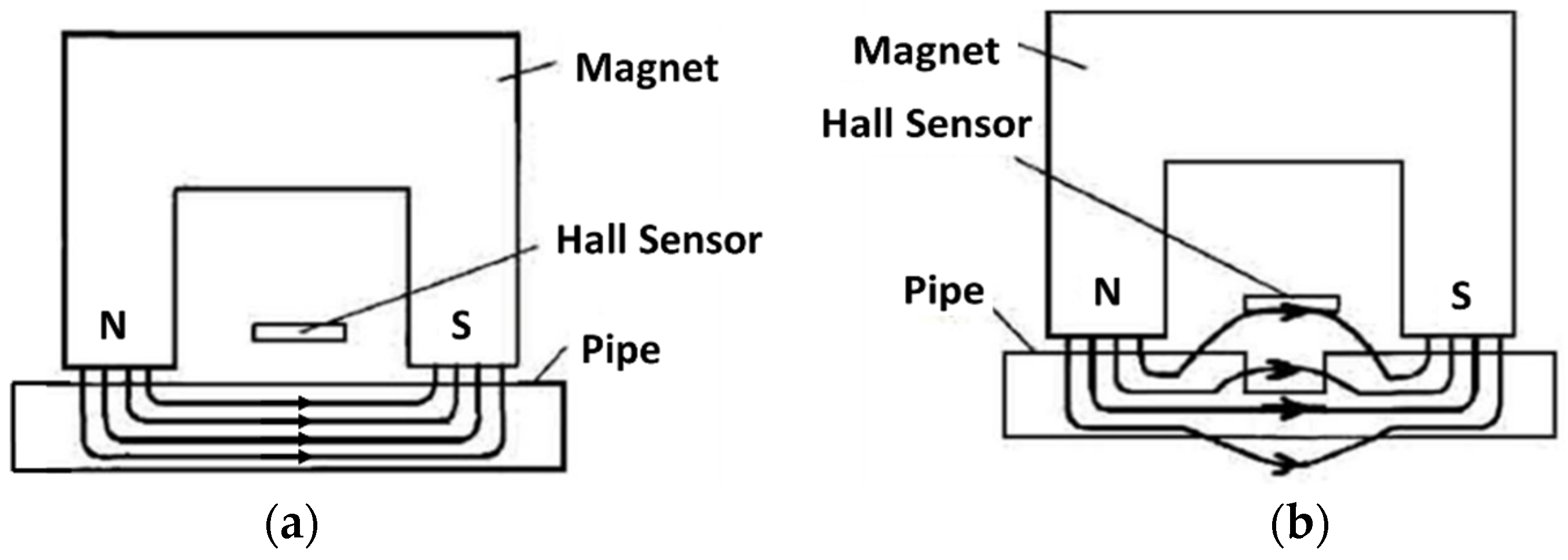
2.5. Magnetic Flux Leakage Method

The magnetic flux leakage (MFL) method is a widely used nondestructive technology to detect anomalies in pipelines. The sensing principle is based on the magnetic properties of steels. When the ferromagnetic material is magnetized close to saturation under the applied magnetic field, the magnetic flux lines will mostly pass through the inside of the material when there are no defects, whereas the defect or corrosion sites will result in bending and leakage of magnetic flux lines [40]. The magnetic field is usually generated by an electromagnet, and a Hall-effect sensor is used to detect the magnetic flux leakage (Figure 6) [41]. The MFL method is good for large area inspection but it is limited for the material surface and near surface detection. Improvements are needed to determine the defect shapes and distinguish between internal and external defects [41].

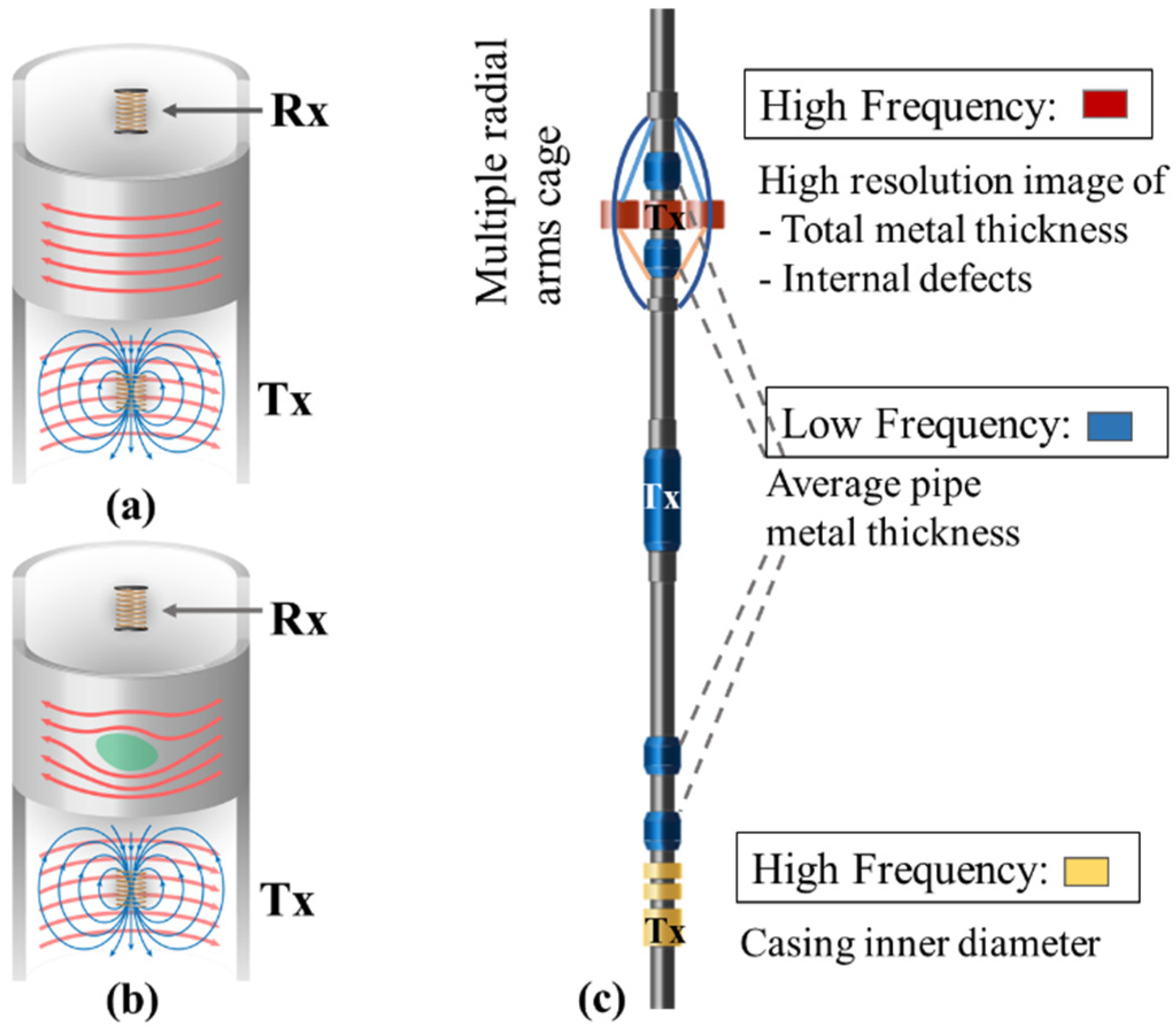
2.6. Multi-Frequency Electromagnetic Sensors

Electromagnetic (EM)-based sensing provides another commonly used non-destructive corrosion monitoring technique. This method is based on the Faraday’s law of induction with many variations available. One example is the multi-frequency EM inspection sensor to detect corrosion and pipeline integrity. The sensor consists of a transmitter coil and a receiver coil. The transmitter coil is excited by an alternating current, and the generated alternating magnetic field induces eddy currents in the surrounding conductive pipes (Figure 7a). The primary EM field from the transmitter combined with a secondary field from eddy currents in the pipes induce a voltage in the separate receiver coil with a phase shift from the primary EM field [3,42,43]. The phase shift and magnitude change are related to the material electrical conductivity, magnetic permeability, and the presence of defects (Figure 7b). The pipe metal thickness can be computed from the low-frequency EM scan, and the high-frequency EM scans can discriminate the inner wall features due to the skin effect (Figure 7c).

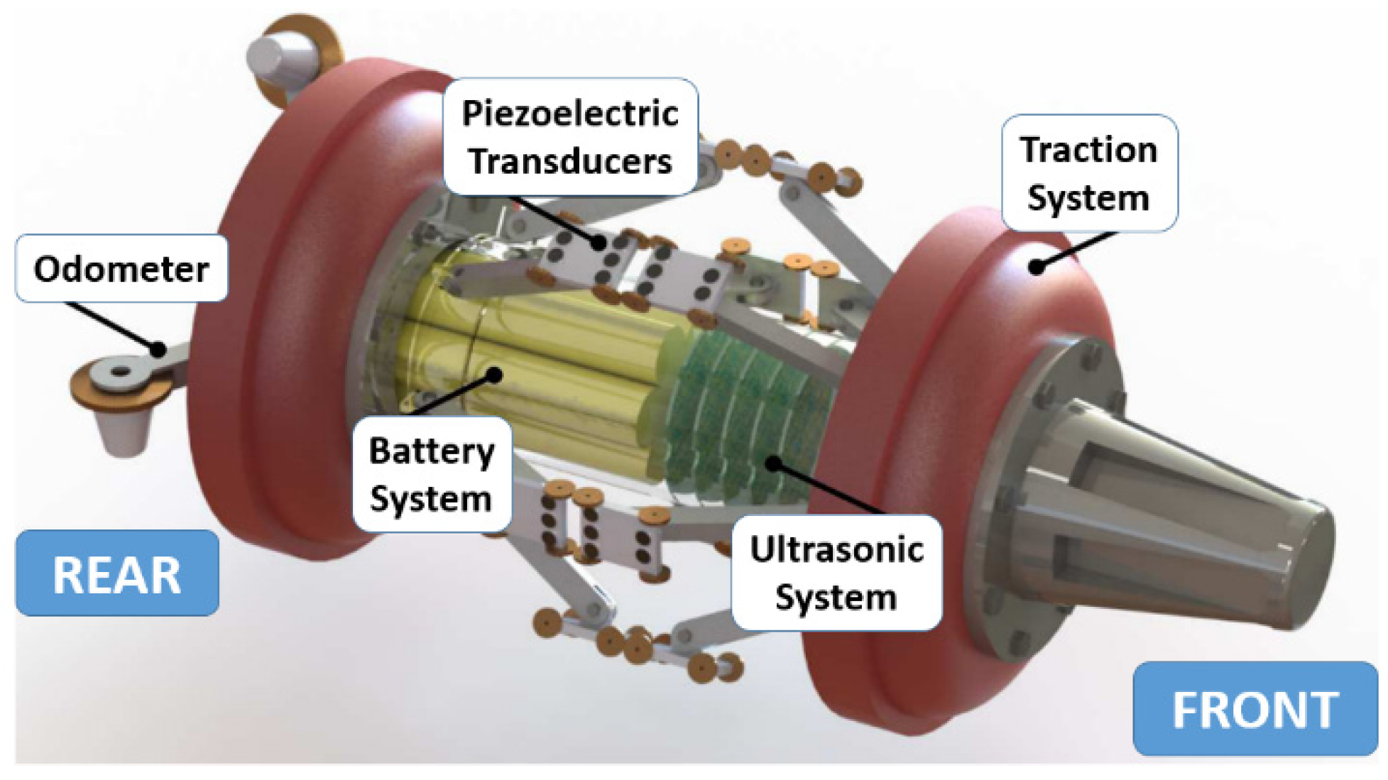
2.7. Pipeline Inspection Gauge

The commercially available pipeline inspection gauges (PIG) or in-line inspection tools (ILI) integrate a selection of sensors and cleaning tools. PIGs can be carried through the pipes by the flow of liquid or gas using the differential pressure while the pipelines are still operating, and they can travel and perform cleaning and inspections over a long distance. The equipped sensors such as UT sensors (Figure 8), MFL sensors, capacitive sensors, and EM sensors can collect data on corrosion, cracking, gouges, and anomalous weld seams [36]. For the inspection purpose, PIG is typically run every 5–7 years set by regulatory requirements or company policies [44,45]. The high cost associated with the PIG service is one main reason for low frequency of use. Despite comprehensive inspection, PIG cannot provide continuous monitoring of pipeline structural health. Therefore, cost-effective continuous corrosion sensors are in demand for the O&G infrastructures.
All the sensors in this review are compared in Table 1 including the emerging technologies of optical fiber sensors and passive wireless sensors to be described in the following sections.

3. Emerging Corrosion Sensing Technologies

3.1. Optical Fiber Sensors

Optical fiber sensors (OFS) have emerged in recent years because of advantages such as nondestructive monitoring, in-situ distributive measurements, long reach, small size, flexibility, geometric versatility, light weight, inherent immunity to electromagnetic interference (EMI), compatibility to optical fiber data communication systems, and improved safety in the presence of flammables compared to electrical-based sensors [46,47,48]. The availability of cost-effective optical fibers and rapid advancement in OFS have stimulated the adoption of OFS in the O&G industry. Reviews on OFS for environmental, chemical, and H2 sensing are already available [47,49,50]. Here, we focus on OFS for corrosion and structural health monitoring in the O&G relevant applications.
According to the spatial distribution of measurements, OFS can be classified as point, quasi-distributed, and distributed. Point sensors monitor corrosion at discrete points, which are assessed by separate channels, i.e., each sensor only detects one point. A quasi-distributed sensor can monitor corrosion at multiple discrete points situated in a single optical channel. Distributed sensing can monitor the parameters continuously along the whole optical fiber with a specific spatial resolution by interrogating the continuously backscattered light [48].

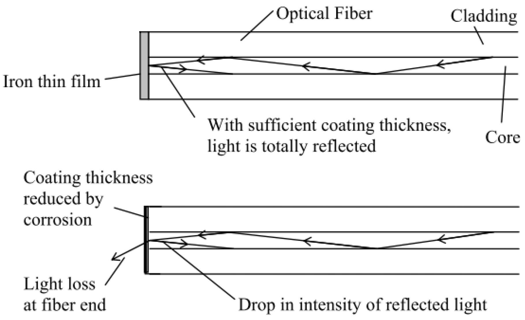
3.1.1. Point OFS for Corrosion

Point corrosion OFS can be considered as the optical version of corrosion coupons. The point OFS usually have a sensing layer coated at one end or one section of optical fibers such as metallic films. The sensing principle of metallic film-coated OFS is based on interactions between photons and electronic structure of the metal in form of light reflection and absorption at the metallic films. As shown in Figure 9, when the metallic film (Fe or Fe–C alloy film) corrodes at the fiber end, the reflected light decreases, which can be detected at the other end of the optical fiber [51,52]. Alternatively, a Fe–C film is coated on a section of the fiber core, and the light transmission along the optical fiber increases as Fe is dissolved/corroded [53]. The corrosion-induced optical response can transmit through the optical fiber for a long distance, but point sensors only provide information at selected locations.
The long-period grating (LPG) provides another design of point sensor allowing light interaction with surrounding medium through the cladding modes. LPG has a typical periodicity (Λ) from 100 µm to 1000 µm, which is longer than that of the fiber Bragg grating (FBG), and couples light from a guided mode in the core into forward propagating cladding modes at certain wavelengths, resulting in dips in the transmission spectrum (Figure 10). These resonant wavelengths (λR) can be expressed as in Equation (6) in terms of the periodicity and the difference between effective refractive indices of the fiber core and cladding modes [54].
λR = (neff,co − neff,cl,m) Λ
where neff,co and neff,cl,m are the effective refractive indices of the core and cladding modes, respectively. The resonant wavelengths are sensitive to changes in temperature, strain, or effective refractive indices of the cladding modes [55,56]. The cladding modes enable external environmental monitoring such as chemical or corrosion sensing. Compared with FBG, LPG shows almost an order of magnitude higher spectral shifts and is easier to fabricate due to the longer periodicity [55]. A multiplex of LPGs has been envisaged with different Λ and/or effective indices along the same fiber for quasi-distributed sensing; however, the multiple resonance peaks and large bandwidth of LPGs limit the multiplexing capabilities. Therefore, LPG sensors are mostly considered as point sensors. Based on the LPG sensitivity to the cladding mode refractive indices, a LPG fiber with a micro-layer of nano-iron and silica particles coated on the cladding has been demonstrated to monitor corrosion as the layer thickness and the sizes of iron particles get smaller in corrosive environments [57,58]. The LPG sensor with an electroplated Fe–C coating has been studied to monitor corrosion-induced mass loss [59,60]. LPG sensors can also monitor environmental parameters related to corrosion such as pH [61,62,63,64], humidity [65,66,67,68], CO2 [69,70,71], H2S [72,73], Cl and salinity [74,75,76,77]. More details on LPG based sensors can be found in References [56,78].

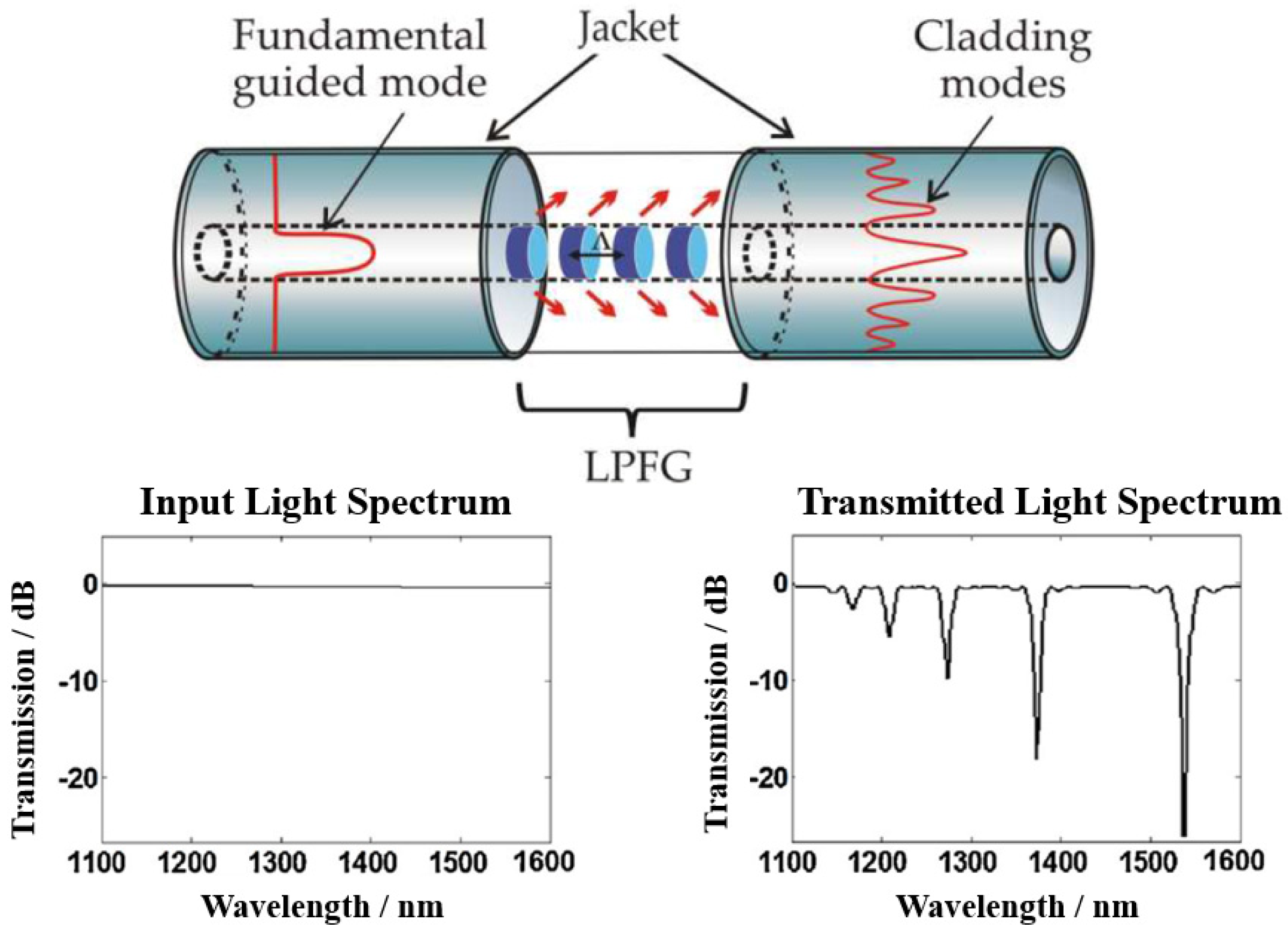
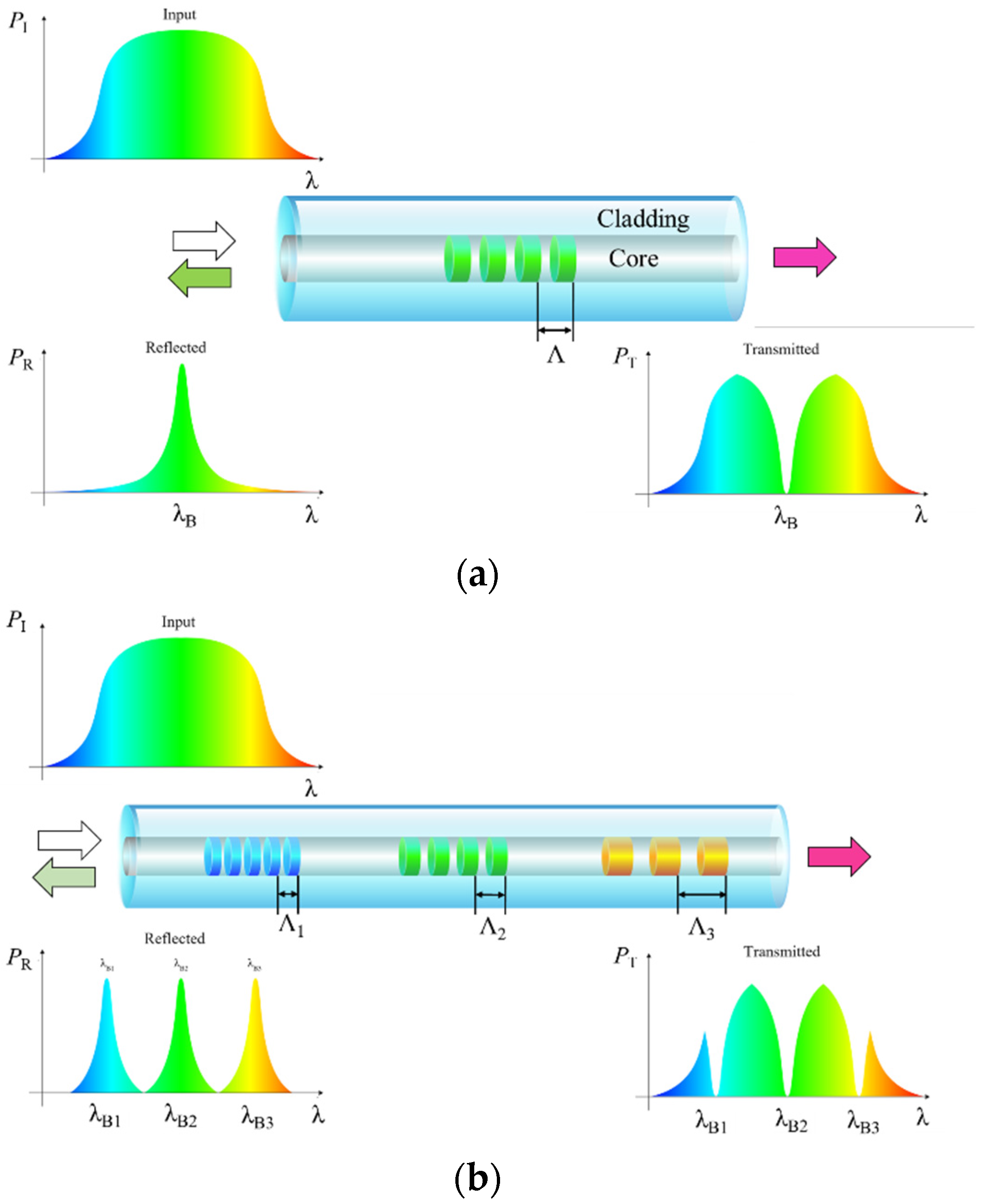
3.1.2. Quasi-Distributed OFS for Corrosion

Fiber Bragg grating-based sensors can be point or quasi-distributed sensors. As shown in Figure 11a, periodic gratings (periodicity Λ) along the core of an optical fiber lead to reflection of a certain wavelength (Bragg wavelength, λB) and transmission of other wavelengths, following Equation (7) [47]. The environmental changes such as temperature and strain changes will cause shifting in the Bragg wavelength for each FBG sensor. Based on this principle, FBG-based sensors are capable of monitoring changes in parameters (e.g., temperature and strain) associated with corrosion in pipelines and wellbores. Several FBGs can be written along the same fiber with different Λ and/or effective indices (neff), leading to several different Bragg wavelengths that can be spatially resolved along the optical fiber based on the reflected or transmitted spectrum (Figure 11b), enabling quasi-distributed sensing [48,81].
λB = 2 neff Λ
FBG-based pressure sensors can be used to locate the pipeline leak based on the negative pressure wave (NPW) method. The onset of pipeline leak induces a pressure drop which propagates in both directions from the leak location, and the induced NPW will reach the FBG pressure sensors mounted on the pipe with time recorded through which the leak location can be computed [82,83]. The FBG-based strain sensors have been used to monitor the hoop strain (circumferential strain) of pipelines as an indicator of inner pressure fluctuation and the wall thickness reduction of pipelines (Figure 12a) [84,85,86]. It has also been reported that the FBG-based strain sensors were bonded directly on the surface of steel pipelines or inserted in the epoxy composite layers to measure the strain of repaired pipes [87]. Moreover, the FBG-based sensors have been installed onto the risers in field tests to demonstrate monitoring of the riser stress for subsea drilling and operations (Figure 12b) [88,89,90]. When coated with pH responsive hydrogel or hygroscopic polymers, FBG structures can also be used as pH or water sensors due to the mechanical expansion of the hydrogel or polymers [91,92,93].

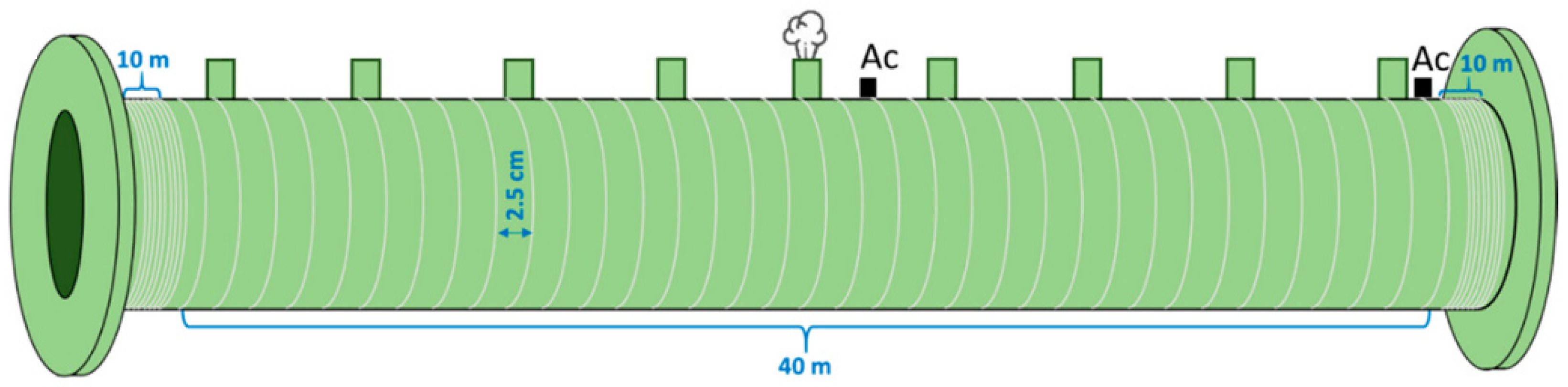
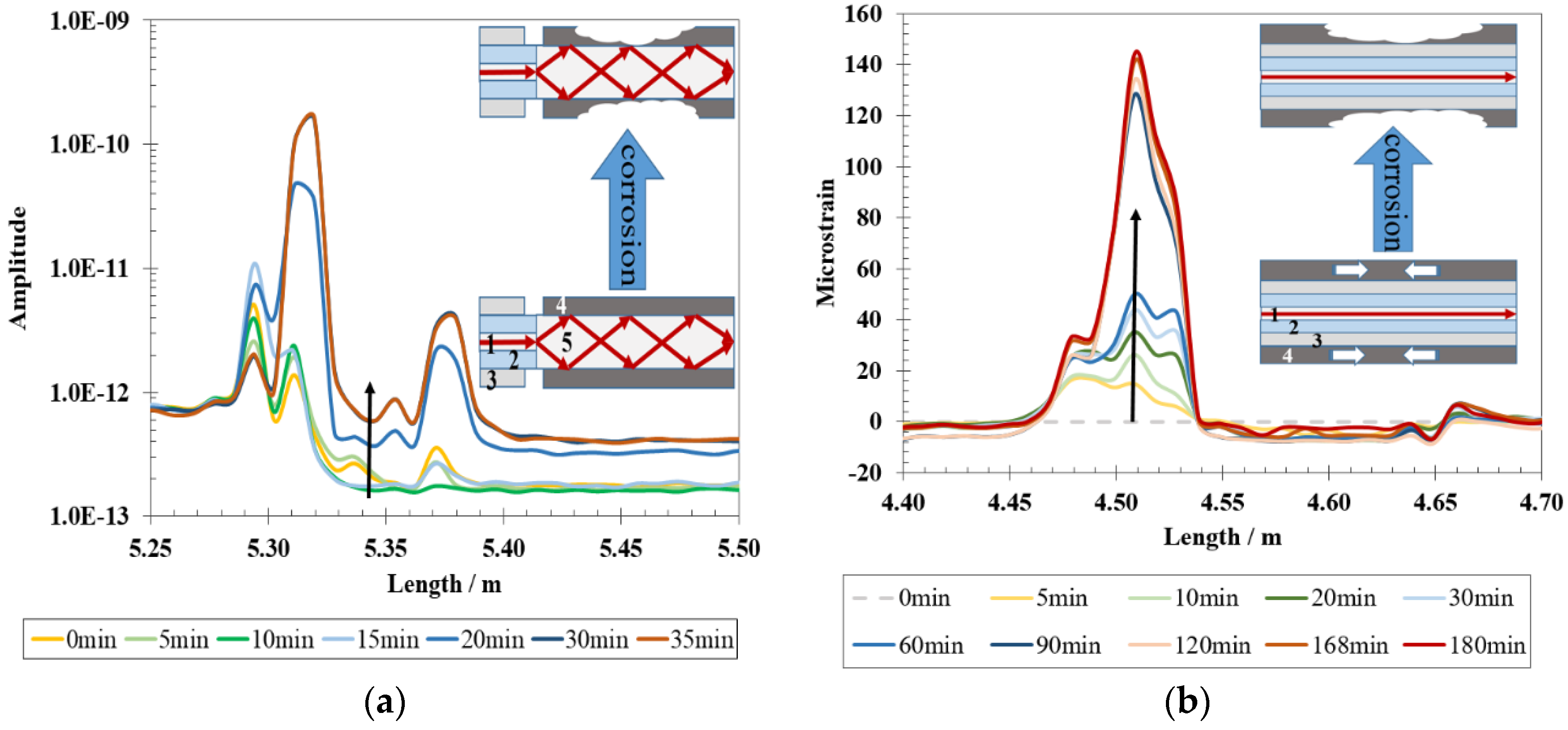
3.1.3. Distributed OFS for Physical Sensing

Distributed monitoring is a significant capability of OFS technology and is particularly suitable for long-distance infrastructures in the O&G industry such as thousands of miles of transmission pipelines. Compared to point sensors, distributed OFS enable continuous real-time monitoring over the whole structure with reduced cost per unit of length. Distributed OFS are based on the light backscattering at discontinuities along the optical fiber. There are three kinds of scattering: Rayleigh, Brillouin, and Raman scattering [47]. As shown in Figure 13, Rayleigh scattering is an elastic scattering caused by local fluctuations of the refractive index and is sensitive to surrounding changes such as temperature, strain/bending, and vibration. Brillouin scattering is an inelastic scattering caused by interaction with acoustic waves from lattice vibration and is sensitive to local temperature, strains, and deformation of the optical fiber. Raman scattering is another inelastic scattering caused by energy exchanges with molecular vibrations of the fiber. The anti-Stokes Raman scattering responds to the temperature changes whereas the Stokes Raman scattering is insensitive; therefore, the ratio of Stokes to anti-Stokes Raman scattering can be used to measure temperature [47,94]. The optical signals can be interrogated using Optical Time-Domain Reflectometry (OTDR) or Optical Frequency-Domain Reflectometry (OFDR) to realize spatially distributed monitoring. A detailed comparison on distributed interrogation techniques in terms of principle, resolution, limitation, and sensitivity can be found in Reference [95], including Brillouin OTDR, Raman OTDR, Rayleigh OFDR, etc.
Distributed temperature, strain, and acoustic sensing (DTS, DSS, and DAS) have been developed and matured over the last three decades [96], and they have been adopted for corrosion and structural health monitoring through investigations and field tests for the O&G industry. Besides monitoring temperature, strain, and vibration for well logging during O&G exploration [94], distributed OFS have been leveraged to monitor physical parameters related to corrosion, failure, and leak detection. DTS used for leak detection is based on the thermal signatures of the flowing products inside the pipelines. Heating transportation is one way to reduce the viscosity to efficiently flow highly viscous crude oil in the pipes, and the leak of heated oil results in a temperature change outside the pipelines, which can be detected through DTS [97]. Due to the Joule-Thomson effect, the leak of high pressure gas decreases the temperature and the leak of liquids increases the temperature, which allows DTS to detect pipeline leaks [94]. OFDR-based DSS has been studied to monitor wall thickness variation induced by internal corrosion based on the hoop strain monitoring using optical fibers around the pipes [86,98]. DAS, using coherent Rayleigh backscattering, has been investigated for detection of the leak-induced pipeline vibrations, either negative pressure waves or broadband leak-induced acoustic noises, using optical fibers helically wound around the pipes (Figure 14) [99,100]. Importantly, for long-distance monitoring, the sensing range of phase-sensitive OTDR has been demonstrated to be possible for extension to 131.5 km to monitor intrusion in pipelines [101].

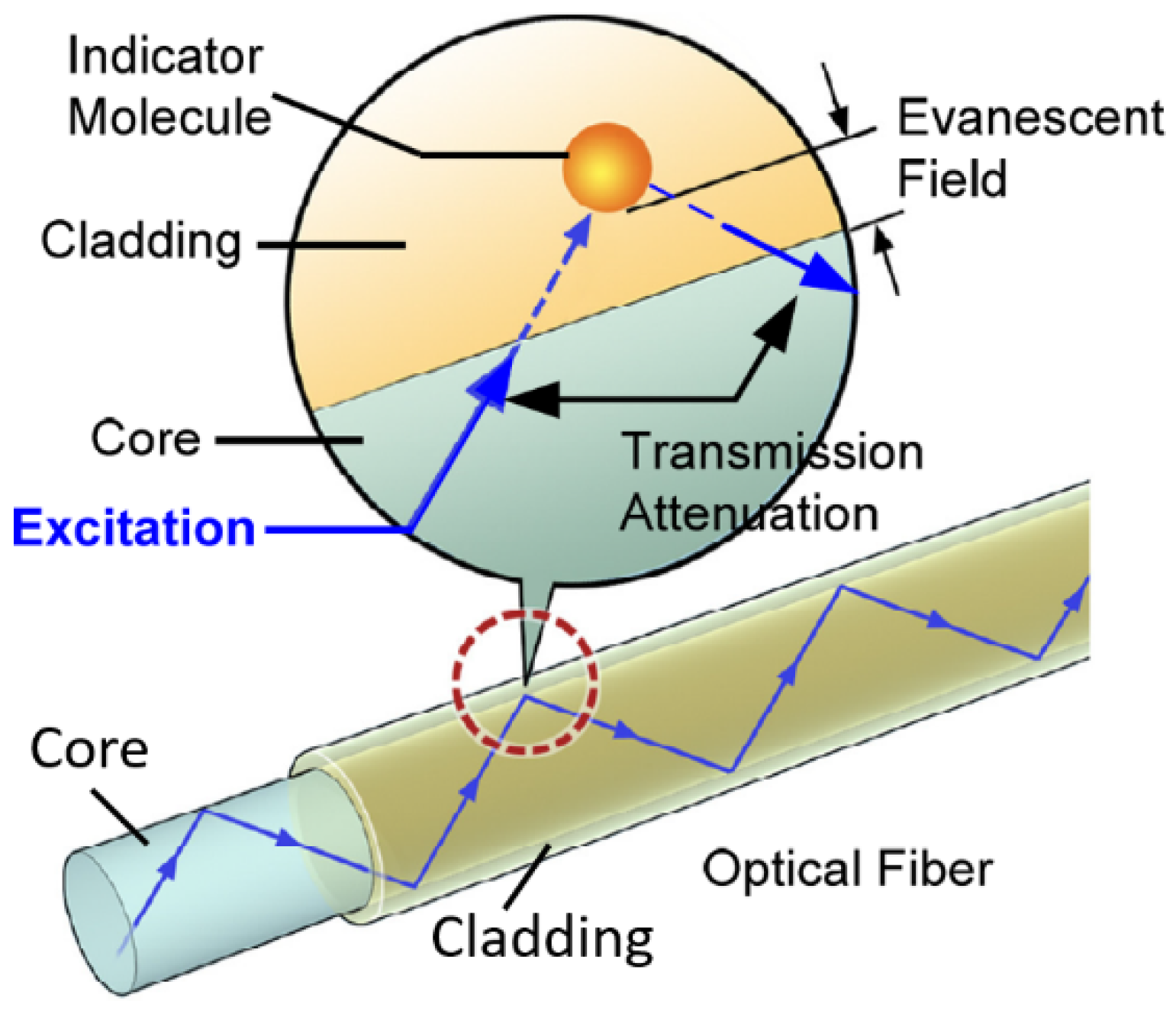
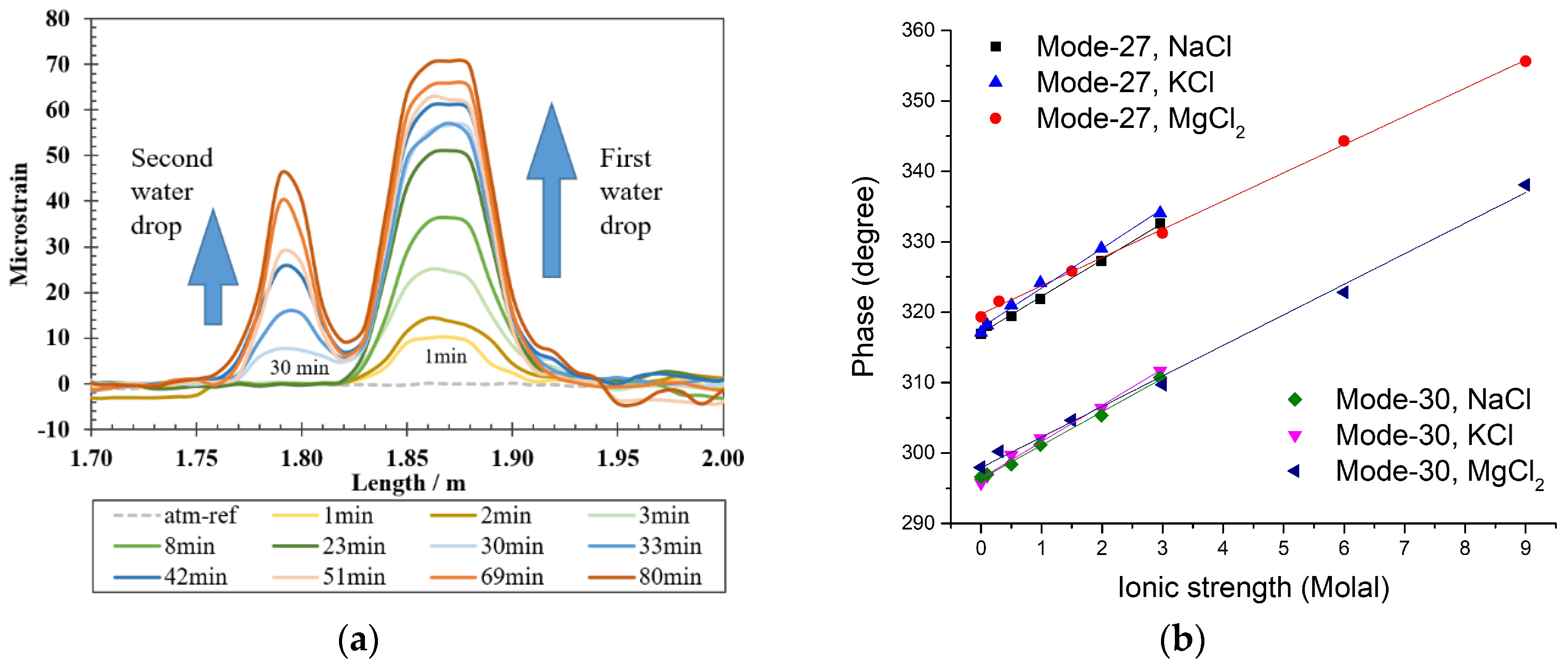
3.1.4. Distributed OFS for Chemical Sensing

Most of the sensors mentioned above are placed outside of the pipelines and measure corrosion indirectly through consequences of corrosion (e.g., temperature, strain, acoustic waves, leak vibration) after corrosion has occurred and the structural integrity is deteriorated; however, it is more ideal to monitor internal corrosion with sensors inside the pipelines and detect early corrosion onset before significant mass loss and structural integrity is compromised.
Distributed chemical sensing (DCS) shows promising potential to monitor corrosive environments (Figure 1) before or upon early corrosion onset to facilitate corrosion mitigation, although DCS is less mature compared to DTS, DSS, and DAS. Optical fiber-based chemical sensors are enabled by functional chemical sensing coatings mostly on the fiber core or cladding, such as metallic films [53,102], oxides [103,104,105,106,107,108,109], polymers [49,110,111,112], nanomaterials [113,114,115], and metal-organic frameworks (MOFs) [116,117]. Figure 15 illustrates one example of the evanescent field-based chemical sensor [118]. The optical fibers can be etched, tapered, spliced, or side-polished to allow the light interactions with chemical sensing layers on the core or cladding and with the surrounding media [47,50,119].
Microstructured optical fibers provide a new type of fiber structure for OFS with great potential for DCS since the inception in the 1990s [120,121,122]. These fibers are featured with air holes running parallel to the longitudinal axis along the entire fiber length. If the air holes are periodically arranged in the cladding matrix, they are also known as photonic crystal fibers (PCF) [120,123]. Hollow-core PCF and index-guided PCF sensors have been demonstrated to detect gases such as methane, H2S, CO2, and acetylene with high sensitivity (ppm level) through direct interaction of light with gases in the holes [124,125,126,127,128]. A suspended-core fiber sensor has been developed for Cl detection with a Cl sensitive fluorescent material filled in the holes [129]. PCF LPG sensors have also been studied for Cl and humidity monitoring [130,131]. A birefringent PCF sensor has been designed to detect corrosion product-induced expansion for corrosion onset monitoring in reinforced concrete [132]. More sensing applications can be found in References [133,134,135]. Although microstructured fibers offer high sensitivity and flexible fiber designs, mass production and commercialization are still limited, which require cost-effective long-distance fabrication of these fibers.
A recent concept for corrosion detection involves the use of proxy materials integrated with the distributed OFS platform to monitor corrosion directly as a distributed optical “corrosion coupon” and provide insights into the corrosive conditions [5,6]. The corrosion-proxy distributed OFS is envisioned to be installed along the inner wall of pipelines to monitor internal corrosion. Metallic film-coated optical fibers have been demonstrated for distributed monitoring of corrosion when interrogated using OFDR. As shown in Figure 16, mass loss of metallic coating is monitored based on (a) intensity change or (b) strain change along the optical fiber [102,136]. The light intensity increases in the corroded region because the light absorption of metallic film decreases as the film becomes thinner. The increase in strain is caused by release of compressive internal stress induced by electroless deposition of Ni film.
Environmental factors such as pH, water content, electrolyte conductivity, and acidic gas CO2 or H2S are critical for corrosion. Distributed sensing of these chemical parameters can determine the environmental corrosivity and therefore indirectly monitor corrosion. Although DCS has only been demonstrated in a few studies [102,137,138,139], the chemical sensing materials investigated for a broader range of fiber optics applications could be potentially utilized for the development of DCS to monitor corrosive environmental factors. There is a variety of pH sensing materials for integration with OFS, including localized surface plasmon resonance (LSPR) Au or Ag nanoparticles (NP) incorporated composites (Figure 17a) [107,140,141], organic dyes [142,143,144,145,146,147], fluorescent molecules [148,149,150,151,152], polymers [153,154,155,156], pH-sensitive hydrogel [157,158,159,160], etc. For the silica matrix coating, the surface charge density of silica matrix was found to correlate with the solution pH regardless of incorporated materials in the matrix layer (Figure 17b) [107,161]. Optical fiber pH sensors and pH sensitive materials are reviewed in more detail in References [160,162,163].
Water and salinity can also be monitored by OFS. Water condensation and presence have been detected by a fully distributed water sensor based on the hygroscopic property of the intrinsic polymer jacket of a commercial single-mode (SM) fiber, and the swelling-induced strain changes are spatially interrogated using OFDR (Figure 18a) [138,164]. The coatings of graphene oxide film and polymers (e.g., polyimide) have also been studied for water or humidity monitoring [137,165,166]. A multi-parameter OFS has been developed to detect the water/solution presence, ionic strength, and temperature simultaneously without any coating through analyzing phase shifts in all the modes (Figure 18b), and a sensor network can be designed for internal corrosion monitoring of natural gas transmission pipelines [119]. OFS for Cl and salinity monitoring are mostly based on the refractive index changes detected using tapered optical fiber, U-shaped fiber, SPR coating, or fluorescence sensitive material for chloride [129,167,168,169].
For acidic gas monitoring, gas sensitive coatings or gas absorption layers are often used in OFS. CO2-absorbing MOFs have been studied for CO2 monitoring and demonstrated quick and reversible responses [117,170,171]. Because dissolved CO2 can reduce the solution pH, CO2 sensors also employ pH indicators (colorimetric or fluorescent dyes) within various sensing layers such as silica gel coating, polymer matrix with quantum dots, and sol–gel matrix with silica nanoparticles [172,173,174,175,176,177]. H2S monitoring often utilizes reactive sensing materials such as Ag [178,179], Cu [180,181], ZnO [182,183], CuO doped SnO2 [184], CdO [185], and fluorescent or luminescent indicators [186,187,188]. More H2S sensitive materials can be found in References [189,190].
Table 2 lists some examples of OFS chemical sensing layers for corrosivity monitoring.

3.1.5. Challenges of OFS Application in the O&G Industry

HTHP in the O&G wellbores impose a big challenge on downhole monitoring with harsh conditions due to CO2, H2S, and mechanical stress. The downhole temperature is commonly 150–200 °C, and it can reach as high as 300 °C in some cases [94]. Although OFS possess advantages for downhole sensing (e.g., thermally and chemically stable, small size, light weight, long reach, and no electronics required downhole), silica fibers can suffer from long-term instability and hydrogen darkening due to hydrogen ingress when exposed to hydrogen/water especially at high temperature, thereby dramatically reducing their rated operational temperatures for long-term deployment. The formation of the Si–H bond and adsorption of OH ions cause the extrinsic attenuation along the fiber [195]. A hermetic carbon layer can be added between the cladding and the polymer jacket to protect silica fibers against hydrogen induced attenuation, but this specialty fiber is only rated up to 200 °C [196]. Therefore, protective coatings or proper OFS designs are paramount for HTHP sensing. Alternative fibers such as sapphire fibers can be suitable for extreme high temperature sensing (up to 1800 °C) if the cost and cladding challenges can be overcome and fibers can be produced at sufficient lengths to be relevant for the O&G applications [197].
Distributed interrogation with high resolution over long distances is another challenge for the long-distance O&G infrastructures such as hundreds of thousands of miles of gathering and transmission pipelines. Meanwhile, low-cost interrogation system and effective deployment of optical fiber sensors in the O&G infrastructures are also critical to make OFS more competitive than existing corrosion monitoring technologies. Phase-sensitive OTDR and Brillouin optical time-domain analysis (BOTDA) are promising interrogation approaches for monitoring >100 km distance [100,101,198,199,200]. There is often a trade-off between the interrogation distance and the spatial resolution. For distributed physical sensing, cross-sensitivity between multiple parameters requires discrimination from one another, e.g., T and strain effects [201,202,203,204]. For distributed chemical sensing, most chemical sensing layers require “leakage” of light from the fiber core, resulting in increased loss of light power and therefore limiting the interrogation distance.

3.2. Passsive Wireless Sensors

Passive wireless sensors constitute another emerging technology for structural health monitoring, which do not require active source of energy or active electronics at the sensing location and can wirelessly transfer energy and signals. Elimination of local batteries, active electronics, and electrical wiring is critical to improve sensor stability and durability at HTHP and harsh environments and to make sensors more compatible with moving parts. The wireless feature also makes it possible for monitoring in inaccessible areas. Due to the small size and low cost, passive wireless sensors can be deployed ubiquitously in the system of interest. Passive wireless sensors for corrosion and SHM are mostly based on the passive radio-frequency identification (RFID) and the surface acoustic wave (SAW) techniques [205,206,207,208].

3.2.1. Passive Radio-Frequency Identification Sensors

Passive RFID sensors form a large group of passive wireless sensors for corrosion and SHM, especially the chipless RFID sensors, and they have advantages of low cost, light weight, small size, and wireless remote sensing [206,207]. RFID technology usually consists of three components: a small tag unit (or transponder), a reader (or transceiver), and antennas. Figure 19 shows one example of a passive RFID antenna sensor system [209]. Passive RFID tags receive RF signals from the reader and respond with identity and sensing signals through the antennas [210]. Different from chip-based RFID tags, chipless RFID tags do not have an onboard silicon chip on the circuitry. Chipless RFID sensors categorically have three types: time-domain reflectometry (TDR)-based; frequency modulation-based, and phase-encoded chipless RFID sensors [211]. SAW devices can also be designed to be RFID tags [205,212,213].
RFID sensors can directly monitor corrosion when incorporated with corrosion sensitive proxy materials in the sensor configuration. With a corrosion sensitive link or connector (e.g., metal or steel of interest) between the circuit and antennas on a RFID sensor, the circuit will not be properly energized through antennas to respond back due to corrosion of the link, which indicates occurrence of corrosion [214]. In another design, the EM shielding effect of metallic materials between the reader and the RFID tag is exploited where the plastic-packaged RFID tags are coated/covered with metallic materials or metal-filled conductive paint. When exposed to corrosive environments, degradation of the coating dampens its EM shielding effect and improves communication between the reader and the tag [215,216].
Moreover, corrosion and structural health can be indirectly monitored with RFID sensors. An LC resonator on a passive tag with an interdigitated capacitor has been studied to monitor the coating lift-off from pipelines and water ingress [217]. Defects and cracking progression have been detected using low frequency or (ultra) high frequency RFID antenna-based sensors [207,209,218,219]. Corrosion potential, chloride ion concentration, and pH have been measured using chip-based RFID sensors with integrated sensing electrodes [220,221,222,223]. Chemical sensing functionality can be achieved with suitable films on the RFID tags to monitor, for example, CO2, H2S, humidity and pH [224,225,226]. Sun et al. have demonstrated an innovative RFID corrosion sensor based on Events as Power Source (EPS) where the corrosion process is monitored as an event while powering the wireless sensor [227]. The micro-energy produced by the electrochemical reactions during corrosion is harvested through a supercapacitor-based chip to power the sensor.

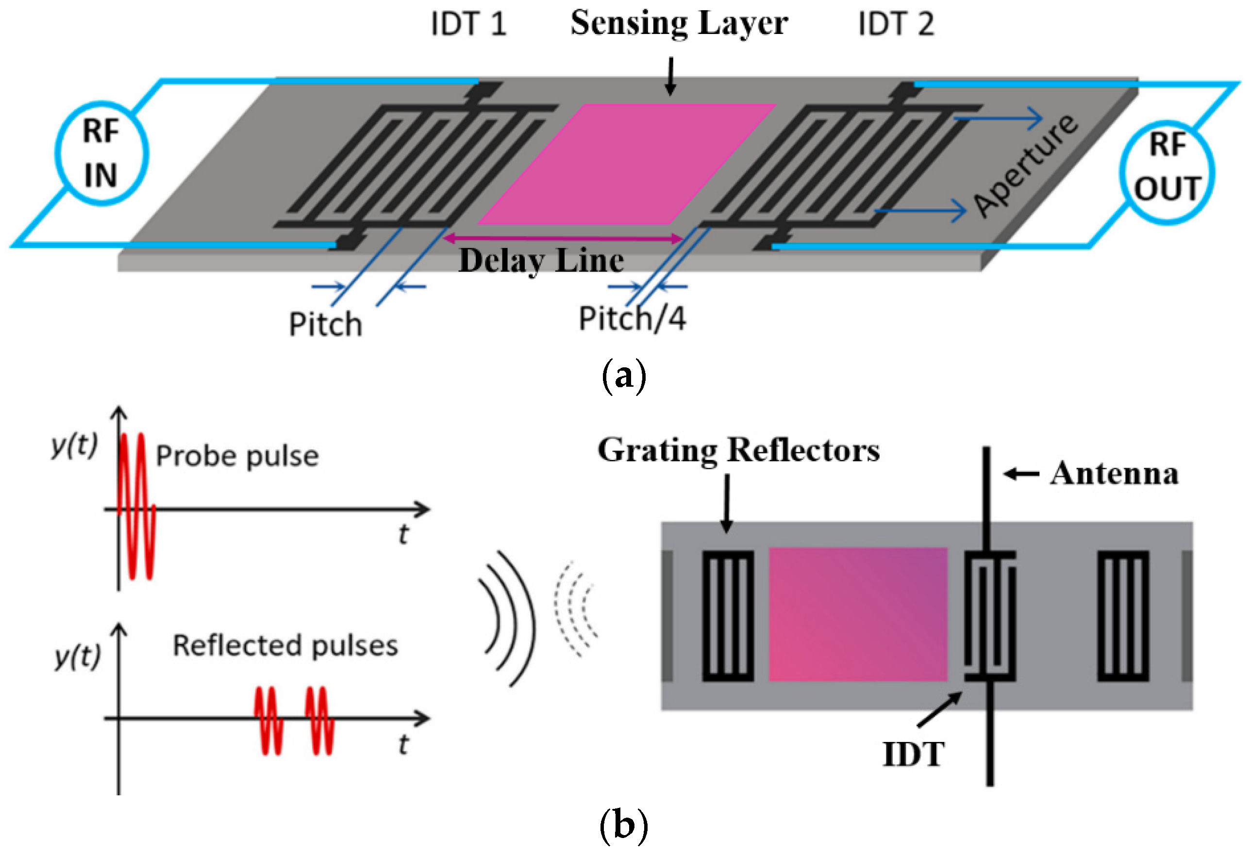
3.2.2. Surface Acoustic Wave Sensors

SAW sensors are of particular interest as passive wireless sensors because of their small size, cost efficiency, ease of fabrication, compatibility with wireless telemetry, and adaptability to many applications (Figure 20). SAW devices consist of interdigitated transducers (IDTs) fabricated on a piezoelectric substrate. IDTs are periodic metallic electrodes (fingers) in the form of two combs intercrossing from opposite sides, and they can convert the RF signal to SAWs on piezoelectric surfaces and vice versa. There are variants of SAWs such as Rayleigh, shear horizontal SAW (SH-SAW), Love, Stoneley, Lamb, and Leaky waves that can be excited on piezoelectric substrates. When the emitting IDT is excited by an external RF signal, SAWs are launched on the piezoelectric substrate and propagate on the substrate surface and perpendicular to the IDT aperture. When the SAWs reach a second IDT, the waves can be converted to output RF signals (Figure 20a) or some waves get reflected back to the emitting IDT for output RF signals. Alternately, when the SAWs reach grating reflectors, they get reflected back to the emitting IDT for RF signal processing (Figure 20b) [228,229]. SAW-based sensing is accomplished by measuring changes in the phase velocity and/or amplitude of the waves caused by property changes in the propagation path such as temperature, mass, electrical, and mechanical changes; therefore, SAW sensors can be employed for monitoring many physical parameters (e.g., temperature [213,230,231,232], pressure [233,234], and strain [235,236]) as well as chemical species in the gaseous and aqueous phases. Detailed reviews on fundamentals of sensing mechanisms and applications can be found in References [228,229,237].
SAW chemical sensors are usually coated with target-specific chemical-sensitive materials such as polymers, MOFs, metals, and metal oxides (Figure 20). For sensing in the gaseous phase, Rayleigh waves are most commonly utilized with gas absorbing or reactive layers coated on the SAW devices as functional sensing layers [229]. Real-time monitoring of the O&G relevant gases such as CO2 and CH4 using SAW sensors coated with MOF materials has been demonstrated in wired and wireless operations (Figure 21) [116,238]. CO2 sensitive polymers or nanomaterials (e.g., graphene) have also been studied for CO2 SAW sensors [239,240,241]. H2S can also be monitored by SAW sensors coated with H2S sensitive films such as CuO, SnO2, Cu, and WO3 [242,243,244,245,246].
Application of SAW sensors in an aqueous medium for detection of corrosion onset or monitoring corrosion stimulants (Table 2) requires consideration of devices with specific wave modes such as SH-SAW [247,248], because not all SAW modes (e.g., the Rayleigh mode) can survive in the aqueous phase. The devices with appropriate SAW modes, when functionalized with specific sensing layers (e.g., Al, ZnO coating), can be adopted to monitor corrosion and chemical parameters that can cause corrosion, thereby leveraging them for the O&G applications [249,250,251,252]. Alternatively, a device with any SAW mode might be used to monitor corrosion when designed to avoid direct contact of propagating acoustic waves with liquids through proper packaging [253]. Additionally, challenges exist with wireless telemetry in the aqueous phase due to strong absorption of typical RF electromagnetic radiation by aqueous solutions.

4. Summary and Outlook

The ability to monitor corrosion online before structural integrity is compromised can have a significant impact on preventing catastrophic events resulting from corrosion. Corrosion sensors for structural health monitoring in the O&G industry have been reviewed including conventional corrosion sensors and emerging sensor technologies in terms of sensor designs, advantages, and limitations. Corrosion sensors can be generally categorized into two types: direct and indirect corrosion sensors. Conventional corrosion sensors encompass corrosion coupons, electrical resistance probes, electrochemical sensors, ultrasonic testing sensors, magnetic flux leakage sensors, electromagnetic sensors, and pipeline inspection gauges. The emerging sensor technologies highlight optical fiber sensors and passive wireless sensors such as RFID and SAW sensors.
Optical fiber sensors have the advantages of nondestructive monitoring, in-situ distributive measurements, long reach, small size, light weight, flexibility, inherent immunity to EMI, compatibility to optical fiber data communication systems, and improved safety in the presence of flammable gas/oil compared to electrical-based sensors. According to spatial distribution of the measurements, OFS can be classified as point, quasi-distributed, and distributed with different sensing principles and interrogation methods. Distributed monitoring enabled by the OFS technology is particularly suitable for long-distance infrastructures in the O&G industry such as transmission pipelines. DTS, DSS, and DAS have been developed and matured over the last three decades for physical parameter monitoring. As a less mature technology, DCS shows promising potential to detect early corrosion onset and monitor corrosive environments such as direct mass loss, pH, water, salinity, and acidic gases before or upon early corrosion onset and therefore facilitate corrosion mitigation. It is crucial to have effective deployment of optical fiber sensors in the O&G infrastructures with low-cost, long-distance, and high spatial resolution interrogation.
Passive wireless sensors have advantages of small size, cost efficiency, elimination of active power, ease of fabrication, compatibility with wireless telemetry, and adaptability to many applications. Elimination of local batteries, active electronics, and electrical wiring is critical to improve sensor stability and durability at HTHP and harsh environments and to make sensors more compatible with moving parts. Passive RFID sensors have been explored for corrosion and structural health monitoring with versatile designs. SAW sensors have been employed for monitoring many physical parameters (e.g., temperature, pressure, and strain) as well as chemical species in the gaseous and aqueous phases. Due to the small size and low cost, passive wireless sensors can be deployed ubiquitously in the system of interest. Main challenges exist with wireless telemetry in highly attenuating media such as aqueous or muddy conditions.
Both emerging technologies are promising for continuous real-time in-situ corrosion monitoring and SHM of the O&G infrastructure. Additional R&D are required to develop and design chemical sensing materials with high sensitivity, selectivity and stability to integrate with the sensing platforms, especially for HTHP and harsh environments in the subsurface wells or other extreme conditions.

Disclaimer

This work was funded by the Department of Energy, National Energy Technology Laboratory, an agency of the United States Government, through a support contract with Leidos Research Support Team (LRST). Neither the United States Government nor any agency thereof, nor any of their employees, nor LRST, nor any of their employees, makes any warranty, expressed or implied, or assumes any legal liability or responsibility for the accuracy, completeness, or usefulness of any information, apparatus, product, or process disclosed, or represents that its use would not infringe privately owned rights. Reference herein to any specific commercial product, process, or service by trade name, trademark, manufacturer, or otherwise, does not necessarily constitute or imply its endorsement, recommendation, or favoring by the United States Government or any agency thereof. The views and opinions of authors expressed herein do not necessarily state or reflect those of the United States Government or any agency thereof.

Author Contributions

R.F.W. conducted the extensive literature review and wrote the whole manuscript; P.L. reviewed and edited mainly the content on optical fiber sensors; J.D. reviewed and edited mainly the content on passive wireless sensors and magnetic methods; F.L. reviewed and edited the pH sensing materials for optical fiber sensors; M.Z.-M. reviewed and edited the content related to corrosion and conventional corrosion sensors; P.R.O. supervised the research program and critically reviewed and edited the manuscript.

Funding

This work was performed in support of the U.S. Department of Energy’s Fossil Energy Crosscutting Technology Research Program, Briggs White, National Energy Technology Laboratory (NETL) Technology Manager, and the U.S. Department of Energy’s Fossil Energy Oil & Natural Gas Research Program, Jared Ciferno, NETL Technology Manager. The Research was executed through the NETL Research and Innovation Center’s Natural Gas Infrastructure and Embedded Sensor Technology Suite for Wellbore Integrity Monitoring Programs. Research performed by Leidos Research Support Team staff was conducted under the RSS contract 89243318CFE000003. Fei Lu would like to acknowledge the support from the NETL post-graduate program administered by Oak Ridge Institute for Science and Education (ORISE).

Conflicts of Interest

The authors declare no conflict of interest.

References

  1. Beavers, J.A.; Thompson, N.G. External Corrosion of Oil and Natural Gas Pipelines. In ASM Handbook; ASM International: Materials Park, OH, USA, 2006; Volume 13C, pp. 1015–1026. [Google Scholar]
  2. Popoola, L.T.; Grema, A.S.; Latinwo, G.K.; Gutti, B.; Balogun, A.S. Corrosion problems during oil and gas production and its mitigation. Int. J. Ind. Chem. 2013, 4, 1–15. [Google Scholar] [CrossRef]
  3. Brondel, D.; Edwards, R.; Hayman, A.; Hill, D.; Semerad, T. Corrosion in the Oil Industry. Oilf. Rev. 1994, 4, 4–18. [Google Scholar]
  4. Koch, G.H.; Brongers, M.P.; Thompson, N.G.; Virmani, Y.P.; Payer, J.H. Corrosion Costs and Preventive Strategies in the United States; NACE International: Houston, TX, USA, 2002; No. FHWA-RD-01-156; pp. 1–12. [Google Scholar]
  5. Wright, R.F.; Brand, E.R.; Ziomek-Moroz, M.; Tylczak, J.H.; Ohodnicki, P.R. Effect of HCO3− on electrochemical kinetics of carbon steel corrosion in CO2-saturated brines. Electrochim. Acta 2018, 290, 626–638. [Google Scholar] [CrossRef]
  6. Wright, R.F.; Ziomek-moroz, M.; Ohodnicki, P.R. Fe Thin Film Coated Optics for Monitoring Internal Corrosion in Natural Gas Pipelines. In Proceedings of the NACE CORROSION, Phoenix, AZ, USA, 15–19 April 2018. No. 10893. [Google Scholar]
  7. Nesic, S.; Postlethwaite, J.; Olsen, S. An Electrochemical Model for Prediction of Corrosion of Mild Steel in Aqueous Carbon Dioxide Solutions. Corrosion 1996, 52, 280–294. [Google Scholar] [CrossRef]
  8. Sun, W.; Nešić, S. A Mechanistic Model of H2S Corrosion of Mild Steel. In Proceedings of the NACE CORROSION, Nashville, TN, USA, 11–15 March 2007. No. 07655. [Google Scholar]
  9. Zheng, Y.; Ning, J.; Brown, B.; Nesic, S. Electrochemical Model of Mild Steel Corrosion in a Mixed H2S/CO2 Aqueous Environment in the Absence of Protective Corrosion Product Layers. Corrosion 2015, 71, 316–325. [Google Scholar] [CrossRef]
  10. Feng, R.; Beck, J.R.; Hall, D.M.; Buyuksagis, A.; Ziomek-Moroz, M.; Lvov, S.N. Effects of CO2 and H2S on Corrosion of Martensitic Steels in NaCl at Low Temperature. Corrosion 2018, 74, 276–287. [Google Scholar] [CrossRef]
  11. Feng, R.; Beck, J.; Ziomek-Moroz, M.; Lvov, S.N. Electrochemical Corrosion of Ultra-high Strength Carbon Steel in Alkaline Brines Containing Hydrogen Sulfide. Electrochim. Acta 2016, 212, 998–1009. [Google Scholar] [CrossRef] [Green Version]
  12. Feng, R.; Beck, J.; Ziomek-Moroz, M.; Lvov, S.N. High-Temperature Electrochemical Corrosion of Ultra-High Strength Carbon Steel in H2S-Containing Alkaline Brines. Electrochim. Acta 2017, 241, 341–352. [Google Scholar] [CrossRef]
  13. Durr, C.L.; Beavers, J.A. Effect of Oxygen on the Internal Corrosion of Natural Gas Pipelines. In Proceedings of the NACE CORROSION, Denver, CO, USA, 24–29 March 1996. No. 612. [Google Scholar]
  14. Eyu, G.D.; Will, G.; Dekkers, W.; MacLeod, J. Effect of dissolved oxygen and immersion time on the corrosion behaviour of mild steel in bicarbonate/chloride solution. Materials 2016, 9, 748. [Google Scholar] [CrossRef]
  15. Heidersbach, R. Corrosive environments. In Metallurgy and Corrosion Control in Oil and Gas Production; John Wiley & Sons, Inc.: Hoboken, NJ, USA, 2018; pp. 15–45. [Google Scholar]
  16. Ziomek-Moroz, M. Environmentally Assisted Cracking of Drill Pipes in Deep Drilling Oil and Natural Gas Wells. J. Mater. Eng. Perform. 2011, 21, 1061–1069. [Google Scholar] [CrossRef]
  17. Iverson, W.P. Microbial Corrosion of Metals. Adv. Appl. Microbiol. 1987, 32, 1–36. [Google Scholar]
  18. Craig, B. Materials for Deep Oil and Gas Well Construction. Adv. Mater. Process. 2008, 166, 33–35. [Google Scholar]
  19. Perkins, A. Technique for Monitoring Corrosion and Related Parameters in Field Applications; NACE International: Houston, TX, USA, 2012; No. 24203, Publ. 3T199. [Google Scholar]
  20. Agarwala, V.S.; Ahmad, S. Corrosion Detection and Monitoring—A Review. In Proceedings of the NACE CORROSION, Orlando, FL, USA, 26–31 March 2000. No. 00271. [Google Scholar]
  21. Tullmin, M.A.A.; Roberge, P.R.; Little, M.A. Sensors For Aircraft Corrosion-Review and Future Developments. In Proceedings of the NACE CORROSION, New Orleans, LA, USA, 9–14 March 1997. No. 301. [Google Scholar]
  22. Qi, X.; Gelling, V.J. A Review of Different Sensors Applied to Corrosion Detection and Monitoring. Recent Patents Corros. Sci. 2011, 1, 1–7. [Google Scholar] [CrossRef]
  23. ASTM G4-01. Standard Guide for Conducting Corrosion Tests in Field Applications; ASTM International: West Conshohocken, PA, USA, 2008; pp. 1–9. [Google Scholar]
  24. Corrosion Coupons. Available online: https://www.cosasco.com/ci-corrosion-coupons-corrosion-monitoring.html (accessed on 19 August 2019).
  25. Electrical Resistance (ER) Monitoring. Available online: http://www.alspi.com/erintro.htm (accessed on 19 August 2019).
  26. Li, S.; Kim, Y.-G.; Jung, S.; Song, H.-S.; Lee, S.-M. Application of steel thin film electrical resistance sensor for in situ corrosion monitoring. Sens. Actuators B Chem. 2007, 120, 368–377. [Google Scholar] [CrossRef]
  27. Kuang, F.; Zhang, J.; Zou, C.; Shi, T.; Wang, Y.; Zhang, S.; Xu, H. Electrochemical Methods for Corrosion Monitoring: A Survey of Recent Patents. Recent Patents Corros. Sci. 2010, 2, 34–39. [Google Scholar] [CrossRef] [Green Version]
  28. Rinaldi, G. A Literature Review of Corrosion Sensing Methods; Defence R&D Canada – Atlantic: Dartmouth, NS, Canada, 2009. [Google Scholar]
  29. Papavinasam, S.; Doiron, A.; Attard, M.; Demoz, A.; Rahimi, P. Non-Intrusive Techniques to Monitor Internal Corrosion of Oil and Gas Pipelines. In Proceedings of the NACE CORROSION, Salt Lake, UT, USA, 11–15 March 2012. No. 0001261. [Google Scholar]
  30. LPR Corrosion Monitoring Probes. Available online: https://www.cosasco.com/lpr-corrosion-monitoring-probe-7012-7022.html (accessed on 19 August 2019).
  31. Yang, L.; Sridhar, N. Coupled multielectrode array systems and sensors for real-time corrosion monitoring- A review. In Proceedings of the NACE CORROSION, San Diego, CA, USA, 12–16 March 2006. No. 06681. [Google Scholar]
  32. Chiang, K.T.; Yang, L. High-temperature electrochemical sensor for online corrosion monitoring. Corrosion 2010, 66, 095002. [Google Scholar] [CrossRef]
  33. Coupled Multielectrode Array Sensor (CMAS) Probes for Localized Corrosion Monitoring and Electrochemical Studies. Available online: http://www.corrinstruments.com/ins/corprobes.html (accessed on 19 August 2019).
  34. Beck, J.; Hall, D.M.; Ziomek-Moroz, M.; Lvov, S.N. Membrane-Coated Electrochemical Sensor for Corrosion Monitoring in Natural Gas Pipelines. Sens. Transducers 2017, 214, 28–33. [Google Scholar]
  35. Hall, D.M.; Duffy, T.; Ziomek-Moroz, M.; Lvov, S.N. Electrochemical impedance spectroscopy and finite element analysis modeling of a 4-electrode humidity sensor for natural gas transportation pipelines. Rev. Sci. Instrum. 2019, 90, 015005. [Google Scholar] [CrossRef] [PubMed]
  36. Rodríguez-Olivares, N.A.; Cruz-Cruz, J.V.; Gómez-Hernández, A.; Hernández-Alvarado, R.; Nava-Balanzar, L.; Salgado-Jiménez, T.; Soto-Cajiga, J.A. Improvement of ultrasonic pulse generator for automatic pipeline inspection. Sensors 2018, 18, 2950. [Google Scholar] [CrossRef]
  37. Cegla, F. Ultrasonic Monitoring of Corrosion with Permanently Installed Sensors (PIMS). In Sensors, Algorithms and Applications for Structural Health Monitoring; Chapuis, B., Sjerve, E., Eds.; Springer: Cham, Switzerland, 2018; pp. 13–20. ISBN 9783319692333. [Google Scholar]
  38. Lakestani, F.; Coste, J.-F.; Denis, R. Application of ultrasonic Rayleigh waves to thickness measurement of metallic coatings. NDT E Int. 1995, 28, 171–178. [Google Scholar] [CrossRef]
  39. Ultrasonic Corrosion Inspection. Available online: https://www.ndt-global.com/about/our-technology/ut-corrosion-inspection-technology (accessed on 19 August 2019).
  40. Rao, B.P.C. Magnetic Flux Leakage Technique: Basics. J. Non Destr. Test. Eval. 2012, 11, 7–17. [Google Scholar]
  41. Shi, Y.; Zhang, C.; Li, R.; Cai, M.; Jia, G. Theory and application of magnetic flux leakage pipeline detection. Sensors 2015, 15, 31036–31055. [Google Scholar] [CrossRef] [PubMed]
  42. Brill, T.M.; Le Calvez, J.L.; Demichel, C.; Nichols, E.; Bermudez, F.Z. Electromagnetic Casing Inspection Tool for Corrosion Evaluation. In Proceedings of the International Petroleum Technology Conferece, Bangkok, Thailand, 15–17 November 2011. No. IPTC 14865. [Google Scholar]
  43. Wilt, M.; Alumbaugh, D. Electromagnetic methods for development and production: State of the art. Lead. Edge 1998, 4, 487–490. [Google Scholar] [CrossRef]
  44. Kirkwood, M. Why Pig a Pipeline? Available online: http://blog.tdwilliamson.com/why-pig-a-pipeline (accessed on 19 August 2019).
  45. Dahl, J. Optimising of Pipeline Maintenance Using Deposit Profile Technology; University of Stavanger: Stavanger, Norway, 2014. [Google Scholar]
  46. Ye, X.W.; Su, Y.H.; Han, J.P. Structural Health Monitoring of Civil Infrastructure Using Optical Fiber Sensing Technology: A Comprehensive Review. Sci. World J. 2014, 652329, 1–11. [Google Scholar] [CrossRef] [PubMed]
  47. Joe, H.-E.; Yun, H.; Jo, S.-H.; Jun, M.B.G.; Min, B.-K. A review on optical fiber sensors for environmental monitoring. Int. J. Precis. Eng. Manuf. Technol. 2018, 5, 173–191. [Google Scholar] [CrossRef]
  48. Lopez-Higuera, J.M.; Rodriguez Cobo, L.; Quintela Incera, A.; Cobo, A. Fiber Optic Sensors in Structural Health Monitoring. J. Light. Technol. 2011, 29, 587–608. [Google Scholar] [CrossRef]
  49. Yin, M.-J.; Gu, B.; An, Q.-F.; Yang, C.; Guan, Y.L.; Yong, K.-T. Recent development of fiber-optic chemical sensors and biosensors: Mechanisms, materials, micro/nano-fabrications and applications. Coord. Chem. Rev. 2018, 376, 348–392. [Google Scholar] [CrossRef]
  50. Zhang, Y.; Peng, H.; Qian, X.; Zhang, Y.; An, G.; Zhao, Y. Recent advancements in optical fiber hydrogen sensors. Sens. Actuators B Chem. 2017, 244, 393–416. [Google Scholar] [CrossRef] [Green Version]
  51. Qiao, G.; Zhou, Z.; Ou, J. Thin Fe-C alloy solid film based fiber optic corrosion sensor. In Proceedings of the Proceedings of 1st IEEE International Conference on Nano/Micro Engineered and Molecular Systems, Zhuhai, China, 18–21 January 2006; pp. 541–544. [Google Scholar]
  52. Leung, C.K.Y.; Wan, K.T.; Chen, L. A Novel Optical Fiber Sensor for Steel Corrosion in Concrete Structures. Sensors 2008, 8, 1960–1976. [Google Scholar] [CrossRef] [Green Version]
  53. Dong, S.; Liao, Y.; Tian, Q.; Luo, Y.; Qiu, Z.; Song, S. Optical and electrochemical measurements for optical fibre corrosion sensing techniques. Corros. Sci. 2006, 48, 1746–1756. [Google Scholar] [CrossRef]
  54. Bhatia, V.; D’Alberto, T.; Murphy, K.A.; Claus, R.O.; Nemarich, C.P. Comparison of optical fiber long- period and Bragg grating sensors. In Proceedings of the Proc. SPIE 2718, Smart Structures and Materials 1996: Smart Sensing, Processing, and Instrumentation, San Diego, CA, USA, 30 May 1996; pp. 110–121. [Google Scholar]
  55. Bhatia, V.; Vengsarkar, A.M. Optical fiber long-period grating sensors. Opt. Lett. 1996, 21, 692–694. [Google Scholar] [CrossRef] [PubMed]
  56. James, S.W.; Tatam, R.P. Optical fibre long-period grating sensors: characteristics and application. Meas. Sci. Technol. 2003, 14, R49–R61. [Google Scholar] [CrossRef] [Green Version]
  57. Huang, Y.; Gao, Z.; Chen, G.; Xiao, H. Long period fiber grating sensors coated with nano iron/silica particles for corrosion monitoring. Smart Mater. Struct. 2013, 22, 75018. [Google Scholar] [CrossRef]
  58. Huang, Y.; Tang, F.; Liang, X.; Chen, G.; Xiao, H.; Azarmi, F. Steel bar corrosion monitoring with long-period fiber grating sensors coated with nano iron/silica particles and polyurethane. Struct. Heal. Monit. 2015, 14, 178–189. [Google Scholar] [CrossRef]
  59. Chen, Y.; Tang, F.; Bao, Y.; Tang, Y.; Chen, G. A Fe-C coated long-period fiber grating sensor for corrosion-induced mass loss measurement. Opt. Lett. 2016, 41, 2306–2309. [Google Scholar] [CrossRef] [PubMed]
  60. Guo, C.; Fan, L.; Wu, C.; Chen, G.; Li, W. Ultrasensitive LPFG corrosion sensor with Fe-C coating electroplated on a Gr/AgNW film. Sens. Actuators B Chem. 2019, 283, 334–342. [Google Scholar] [CrossRef]
  61. Corres, J.M.; del Villar, I.; Matias, I.R.; Arregui, F.J. Fiber-optic pH-sensors in long-period fiber gratings using electrostatic self-assembly. Opt. Lett. 2007, 32, 29–31. [Google Scholar] [CrossRef] [PubMed]
  62. Wang, K.; Klimov, D.; Zbigniew, K. Seawater pH sensor based on the long period grating in a single-mode–multimode–single-mode structure. Opt. Eng. 2009, 48, 034401. [Google Scholar] [CrossRef]
  63. Mau, J.-C.; Lin, G.-R.; Fu, M.-Y.; Liu, W.-F. A Fiber Optic Sensor Based on Ari-Gap Long Period Gratings for pH Sensing Application. Microw. Opt. Technol. Lett. 2013, 55, 855–857. [Google Scholar] [CrossRef]
  64. Mishra, S.K.; Zou, B.; Chiang, K.S. Wide-Range pH Sensor Based on a Smart-Hydrogel-Coated Long-Period Fiber Grating. IEEE J. Sel. Top. Quantum Electron. 2017, 23, 5601405. [Google Scholar] [CrossRef]
  65. Wang, L.; Liu, Y.; Zhang, M.; Tu, D.; Mao, X.; Liao, Y. A relative humidity sensor using a hydrogel-coated long period grating. Meas. Sci. Technol. 2007, 18, 3131–3134. [Google Scholar] [CrossRef]
  66. Venugopalan, T.; Sun, T.; Grattan, K.T.V. Long period grating-based humidity sensor for potential structural health monitoring. Sens. Actuators A Phys. 2008, 148, 57–62. [Google Scholar] [CrossRef]
  67. Wang, Y.; Liu, Y.; Zou, F.; Jiang, C.; Mou, C.; Wang, T. Humidity Sensor Based on a Long-Period Fiber Grating Coated with Polymer Composite Film. Sensors 2019, 19, 2263. [Google Scholar] [CrossRef] [PubMed]
  68. Alwis, L.; Sun, T.; Grattan, K.V. Analysis of polyimide-coated optical fiber long-period grating-based relative humidity sensor. IEEE Sens. J. 2013, 13, 767–771. [Google Scholar] [CrossRef]
  69. Hromadka, J.; Tokay, B.; Correia, R.; Morgan, S.P.; Korposh, S. Carbon dioxide measurements using long period grating optical fibre sensor coated with metal organic framework HKUST-1. Sens. Actuators B Chem. 2018, 255, 2483–2494. [Google Scholar] [CrossRef]
  70. Melo, L.; Burton, G.; Davies, B.; Risk, D.; Wild, P. Highly sensitive coated long period grating sensor for CO2 detection at atmospheric pressure. Sens. Actuators B Chem. 2014, 202, 294–300. [Google Scholar] [CrossRef]
  71. Bao, B.; Melo, L.; Davies, B.; Fadaei, H.; Sinton, D.; Wild, P. Detecting supercritical CO2 in brine at sequestration pressure with an optical fiber sensor. Environ. Sci. Technol. 2013, 47, 306–313. [Google Scholar] [CrossRef] [PubMed]
  72. Qin, X.; Feng, W.; Yang, X.; Wei, J.; Huang, G. Molybdenum sulfide/citric acid composite membrane-coated long period fiber grating sensor for measuring trace hydrogen sulfide gas. Sens. Actuators B Chem. 2018, 272, 60–68. [Google Scholar] [CrossRef]
  73. Chen, R.; Liu, W.; Huang, G.; Wang, D.; Qin, X.; Feng, W. Hydrogen sulfide sensor based on tapered fiber sandwiched between two molybdenum disulfide/citric acid composite membrane coated long-period fiber gratings. Appl. Opt. 2018, 57, 9755. [Google Scholar] [CrossRef]
  74. Chung, C.; Lam, C.; Mandamparambil, R.; Sun, T.; Grattan, K.T.V.; Nanukuttan, S.V.; Taylor, S.E.; Basheer, P.A.M. Optical Fiber Refractive Index Sensor for Chloride Ion Monitoring. IEEE Sens. J. 2009, 9, 525–532. [Google Scholar]
  75. Abi Kaed Bey, S.K.; Lam, C.C.C.; Sun, T.; Grattan, K.T.V. Chloride ion optical sensing using a long period grating pair. Sens. Actuators A Phys. 2008, 141, 390–395. [Google Scholar] [CrossRef]
  76. Yang, F.; Hlushko, R.; Wu, D.; Sukhishvili, S.A.; Du, H.; Tian, F. Ocean Salinity Sensing Using Long-Period Fiber Gratings Functionalized with Layer-by-Layer Hydrogels. ACS Omega 2019, 4, 2134–2141. [Google Scholar] [CrossRef] [PubMed] [Green Version]
  77. Tsuda, H.; Urabe, K. Characterization of long-period grating refractive index sensors and their applications. Sensors 2009, 9, 4559–4571. [Google Scholar] [CrossRef] [PubMed]
  78. Zhao, X.-W.; Wang, Q. Mini review: Recent advances in long period fiber grating biological and chemical sensors. Instrum. Sci. Technol. 2019, 47, 140–169. [Google Scholar] [CrossRef]
  79. Silva, C.; Coelho, J.M.P.; Caldas, P.; Jorge, P. Fibre Sensing System Based on Long-Period Gratings for Monitoring Aqueous Environments. In Fiber Optic Sensors; Yasin, M., Ed.; InTech: Rijeka, Croatia, 2012; pp. 317–342. ISBN 978-953-307-922-6. [Google Scholar]
  80. Urrutia, A.; Goicoechea, J.; Ricchiuti, A.L.; Barrera, D.; Sales, S.; Arregui, F.J. Simultaneous measurement of humidity and temperature based on a partially coated optical fiber long period grating. Sens. Actuators B Chem. 2016, 227, 135–141. [Google Scholar] [CrossRef] [Green Version]
  81. Moon, H.M.; Kwak, S.C.; Im, K.; Kim, J.B.; Kim, S. Wavelength Interrogation System for Quasi-Distributed Fiber Bragg Grating Temperature Sensors Based on a 50-GHz Array Waveguide Grating. IEEE Sens. J. 2019, 19, 2598–2604. [Google Scholar] [CrossRef]
  82. Hou, Q.; Ren, L.; Jiao, W.; Zou, P.; Song, G. An Improved Negative Pressure Wave Method for Natural Gas Pipeline Leak Location Using FBG Based Strain Sensor and Wavelet Transform. Math. Probl. Eng. 2013, 278794, 1–8. [Google Scholar] [CrossRef]
  83. Wang, J.; Zhao, L.; Liu, T.; Li, Z.; Sun, T.; Grattan, K.T.V. Novel Negative Pressure Wave-Based Pipeline Leak Detection System Using Fiber Bragg Grating-Based Pressure Sensors. J. Light. Technol. 2017, 35, 3366–3373. [Google Scholar] [CrossRef]
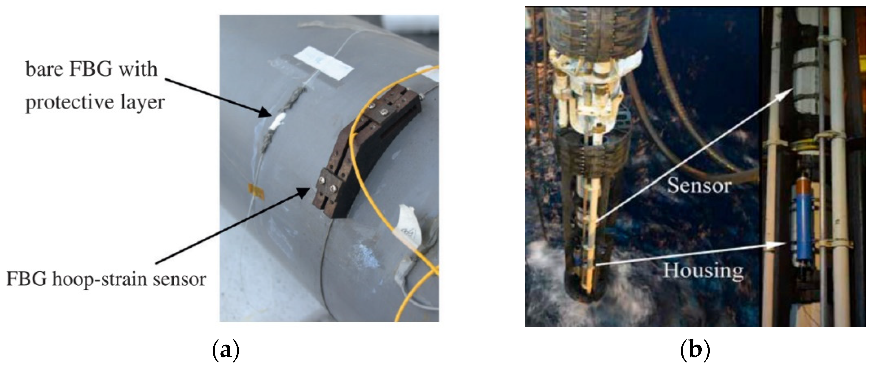
  84. Ren, L.; Jia, Z.G.; Li, H.N.; Song, G. Design and experimental study on FBG hoop-strain sensor in pipeline monitoring. Opt. Fiber Technol. 2014, 20, 15–23. [Google Scholar] [CrossRef]
  85. Jiang, T.; Li, D.; Ren, L.; Jia, Z.; Li, H. Application of FBG Based Sensor in Pipeline Safety Monitoring. Appl. Sci. 2017, 7, 540. [Google Scholar] [CrossRef]
  86. Li, H.; Li, D.; Ren, L.; Jiang, T.; Jia, Z. Pipeline internal corrosion monitoring based on distributed strain measurement technique. Struct. Control Heal. Monit. 2017, 24, e2016. [Google Scholar]
  87. Freire, J.L.F.; Perrut, V.A.; Braga, A.M.B.; Vieira, R.D.; Ribeiro, A.S.; Rosas, M.A.P. Use of FBG Strain Gages on a Pipeline Specimen Repaired With a CFRE Composite. Exp. Tech. 2012, 39, 70–79. [Google Scholar] [CrossRef]
  88. Xu, J.; Yang, D.; Qin, C.; Jiang, Y.; Sheng, L.; Jia, X.; Bai, Y.; Shen, X.; Wang, H.; Deng, X.; et al. Study and test of a new bundle-structure riser stress monitoring sensor based on FBG. Sensors 2015, 15, 29648–29660. [Google Scholar] [CrossRef] [PubMed]
  89. Morrison, D.G.; Dean, J.R. Apparatuses and Methods for Monitoring Stress in Steel Catenary Risers. U.S. Patent US007194913B2, 27 March 2007. [Google Scholar]
  90. Brower, D.V.; Prescott, N. Real Time Subsea Monitoring and Control Smart Field Solutions. In Proceedings of the Subsea Rio 2004 Conference, Rio de Janeiro, Brazil, 3 June 2004; pp. 1–13. [Google Scholar]
  91. Yulianti, I.; Supa’at, A.S.M.; Idrus, S.M.; Kurdi, O.; Anwar, M.R.S. Sensitivity improvement of a fibre Bragg grating pH sensor with elastomeric coating. Meas. Sci. Technol. 2012, 23, 015104. [Google Scholar] [CrossRef]
  92. Lin, Y.; Chen, S.; Wang, M.; Liu, W. Fiber-optic fast response pH sensor in fiber Bragg gating using intelligent hydrogel coatings. Opt. Eng. 2015, 54, 057107. [Google Scholar] [CrossRef]
  93. Yeo, T.L.; Sun, T.; Grattan, K.T.V.; Parry, D.; Lade, R.; Powell, B.D. Characterisation of a polymer-coated fibre Bragg grating sensor for relative humidity sensing. Sens. Actuators B Chem. 2005, 110, 148–155. [Google Scholar] [CrossRef]
  94. Yamate, T.; Fujisawa, G.; Ikegami, T. Optical Sensors for the Exploration of Oil and Gas. J. Light. Technol. 2017, 35, 3538–3545. [Google Scholar] [CrossRef]
  95. Bao, X.; Chen, L. Recent Progress in Distributed Fiber Optic Sensors. Sensors 2012, 12, 8601–8639. [Google Scholar] [CrossRef] [Green Version]
  96. Ukil, A.; Braendle, H.; Krippner, P. Distributed temperature sensing: Review of technology and applications. IEEE Sens. J. 2012, 12, 885–892. [Google Scholar] [CrossRef]
  97. Mirzaei, A.; Bahrampour, A.R.; Taraz, M.; Bahrampour, A.; Bahrampour, M.J.; Ahmadi Foroushani, S.M. Transient response of buried oil pipelines fiber optic leak detector based on the distributed temperature measurement. Int. J. Heat Mass Transf. 2013, 65, 110–122. [Google Scholar] [CrossRef]
  98. Wong, L.; Rathnayaka, S.; Chiu, W.K.; Kodikara, J. Fatigue Damage Monitoring of a Cast Iron Pipeline Using Distributed Optical Fibre Sensors. Procedia Eng. 2017, 188, 293–300. [Google Scholar] [CrossRef]
  99. Stajanca, P.; Chruscicki, S.; Homann, T.; Seifert, S.; Schmidt, D.; Habib, A. Detection of Leak-Induced Pipeline Vibrations Using Fiber—Optic Distributed Acoustic Sensing. Sensors 2018, 18, 2841. [Google Scholar] [CrossRef] [PubMed]
  100. Muanenda, Y. Recent Advances in Distributed Acoustic Sensing Based on Phase-Sensitive Optical Time Domain Reflectometry. J. Sens. 2018, 3897873, 1–16. [Google Scholar] [CrossRef]
  101. Peng, F.; Wu, H.; Jia, X.-H.; Rao, Y.-J.; Wang, Z.-N.; Peng, Z.-P. Ultra-long high-sensitivity Φ-OTDR for high spatial resolution intrusion detection of pipelines. Opt. Express 2014, 22, 13804–13810. [Google Scholar] [CrossRef] [PubMed]
  102. Wright, R.F.; Egbu, J.; Lu, P.; Buric, M.P.; Ziomek-Moroz, M.; Ohodnicki, P.R.J. Electrolessly Coated Optical Fibers for Distributed Corrosion Monitoring. In Proceedings of the NACE CORROSION, Nashville, TN, USA, 24–28 March 2019. No. 13499. [Google Scholar]
  103. Jee, Y.; Yu, Y.; Abernathy, H.W.; Lee, S.; Kalapos, T.L.; Hackett, G.A.; Ohodnicki, P.R. Plasmonic Conducting Metal Oxide-Based Optical Fiber Sensors for Chemical and Intermediate Temperature-Sensing Applications. ACS Appl. Mater. Interfaces 2018, 10, 42552–42563. [Google Scholar] [CrossRef] [PubMed]
  104. Ohodnicki, P.R.; Brown, T.D.; Holcomb, G.R.; Tylczak, J.; Schultz, A.M.; Baltrus, J.P. High temperature optical sensing of gas and temperature using Au-nanoparticle incorporated oxides. Sens. Actuators B Chem. 2014, 202, 489–499. [Google Scholar] [CrossRef]
  105. Yan, M.; Tylczak, J.; Yu, Y.; Panagakos, G.; Ohodnicki, P. Multi-component optical sensing of high temperature gas streams using functional oxide integrated silica based optical fiber sensors. Sens. Actuators B Chem. 2018, 255, 357–365. [Google Scholar] [CrossRef]
  106. Sun, C.; Lu, P.; Wright, R.; Ohodnicki, P.R. Low-cost fiber optic sensor array for simultaneous detection of hydrogen and temperature. In Proceedings of the Proc. SPIE 10654, Fiber Optic Sensors and Applications XV, Orlando, FL, USA, 14 May 2018. No. 1065405. [Google Scholar]
  107. Wang, C.; Ohodnicki, P.R.; Su, X.; Keller, M.; Brown, T.D.; Baltrus, J.P. Novel silica surface charge density mediated control of the optical properties of embedded optically active materials and its application for fiber optic pH sensing at elevated temperatures. Nanoscale 2015, 7, 2527–2535. [Google Scholar] [CrossRef]
  108. Ohodnicki, P.R.; Buric, M.P.; Brown, T.D.; Matranga, C.; Wang, C.; Baltrus, J.; Andio, M. Plasmonic nanocomposite thin film enabled fiber optic sensors for simultaneous gas and temperature sensing at extreme temperatures. Nanoscale 2013, 5, 9030–9039. [Google Scholar] [CrossRef]
  109. Babeva, T.; Andreev, A.; Grand, J.; Vasileva, M.; Karakoleva, E.; Zafirova, B.S.; Georgieva, B.; Koprinarova, J.; Mintova, S. Optical fiber–Ta2O5 waveguide coupler covered with hydrophobic zeolite film for vapor sensing. Sens. Actuators B Chem. 2017, 248, 359–366. [Google Scholar] [CrossRef]
  110. Zhao, Q.; Yin, M.; Zhang, A.P.; Prescher, S.; Antonietti, M.; Yuan, J. Hierarchically structured nanoporous poly(ionic liquid) membranes: Facile preparation and application in fiber-optic pH sensing. J. Am. Chem. Soc. 2013, 135, 5549–5552. [Google Scholar] [CrossRef] [PubMed]
  111. Walsh, J.E.; MacCraith, B.D.; Meaney, M.; Vos, J.G.; Regan, F.; Lancia, A.; Artjushenko, S. Sensing of chlorinated hydrocarbons and pesticides in water using polymer coated mid-infrared optical fibres. Analyst 1996, 121, 789–792. [Google Scholar] [CrossRef]
  112. Scorsone, E.; Christie, S.; Persaud, K.C.; Kvasnik, F. Evanescent sensing of alkaline and acidic vapours using a plastic clad silica fibre doped with poly(o-methoxyaniline). Sens. Actuators B Chem. 2004, 97, 174–181. [Google Scholar] [CrossRef]
  113. Renganathan, B.; Sastikumar, D.; Raj, S.G.; Ganesan, A.R. Fiber optic gas sensors with vanadium oxide and tungsten oxide nanoparticle coated claddings. Opt. Commun. 2014, 315, 74–78. [Google Scholar] [CrossRef]
  114. Ou, J.Z.; Yaacob, M.H.; Campbell, J.L.; Breedon, M.; Kalantar-Zadeh, K.; Wlodarski, W. H2 sensing performance of optical fiber coated with nano-platelet WO3 film. Sens. Actuators B Chem. 2012, 166–167, 1–6. [Google Scholar] [CrossRef]
  115. Mohammed, H.A.; Rahman, N.A.; Ahmad, M.Z.; Abu Bakar, M.H.; Anas, S.B.A.; Mahdi, M.A.; Yaacob, M.H. Sensing Performance of Modified Single Mode Optical Fiber Coated with Nanomaterials-Based Ammonia Sensors Operated in the C-Band. IEEE Access 2019, 7, 5467–5476. [Google Scholar] [CrossRef]
  116. Devkota, J.; Kim, K.J.; Ohodnicki, P.R.; Culp, J.T.; Greve, D.W.; Lekse, J.W. Zeolitic imidazolate framework-coated acoustic sensors for room temperature detection of carbon dioxide and methane. Nanoscale 2018, 10, 8075–8087. [Google Scholar] [CrossRef] [Green Version]
  117. Chong, X.; Kim, K.J.; Li, E.; Zhang, Y.; Ohodnicki, P.R.; Chang, C.H.; Wang, A.X. Near-infrared absorption gas sensing with metal-organic framework on optical fibers. Sens. Actuators B Chem. 2016, 232, 43–51. [Google Scholar] [CrossRef]
  118. Hingerl, F.F.; Marpu, S.; Guzman, N.; Benson, S.M.; Delgado-Alonso, J. Development and testing of a new fiber optic system for monitoring CO2 solubility in aqueous high-pressure geological systems. Energy Procedia 2014, 63, 4134–4144, Under a Creative Commons License. Available online: https://creativecommons.org/licenses/by-nc-nd/4.0/ (accessed on 19 August 2019). [CrossRef]
  119. Lu, P.; Wright, R.F.; Ziomek-Moroz, M.; Buric, M.P.; Zandhuis, P.; Ohodnicki, P.R. A Multifunctional Fiber Optic Sensor for Internal Corrosion Monitoring in Natural Gas Transmission Pipelines. In Proceedings of the NACE CORROSION, Phoenix, AZ, USA, 15–19 April 2018. No. 11429. [Google Scholar]
  120. Knight, J.C.; Broeng, J.; Birks, T.A.; Russell, P.S.J. Photonic Band Gap Guidance in Optical Fibers. Science 1998, 282, 1476–1479. [Google Scholar] [CrossRef]
  121. Monro, T.M.; Belardi, W.; Furusawa, K.; Baggett, J.C.; Broderick, N.G.R.; Richardson, D.J. Sensing with microstructured optical fibres. Meas. Sci. Technol. 2001, 12, 854–858. [Google Scholar] [CrossRef]
  122. Pinto, A.M.R.; Lopez-Amo, M. Photonic Crystal Fibers for Sensing Applications. J. Sens. 2012, 598178, 1–21. [Google Scholar] [CrossRef]
  123. Knight, J.C.; Birks, T.A.; Russell, P.S.J.; Atkin, D.M. All-silica single-mode optical fiber with photonic crystal cladding. Opt. Lett. 1996, 21, 1547–1549. [Google Scholar] [CrossRef] [PubMed]
  124. Kornaszewski, Ł.; Gayraud, N.; Stone, J.M.; Macpherson, W.N.; George, A.K.; Knight, J.C.; Hand, D.P.; Reid, D.T. Mid-infrared methane detection in a photonic bandgap fiber using a broadband optical parametric oscillator. Opt. Express 2007, 15, 11219–11224. [Google Scholar] [CrossRef] [PubMed]
  125. Carvalho, J.P.; Lehmann, H.; Bartelt, H.; Magalhaes, F.; Amezcua-Correa, R.; Santos, J.L.; Van Roosbroeck, J.; Araujo, F.M.; Ferreira, L.A.; Knight, J.C. Remote System for Detection of Low-Levels of Methane Based on Photonic Crystal Fibres and Wavelength Modulation Spectroscopy. J. Sens. 2009, 398403, 1–10. [Google Scholar] [CrossRef]
  126. Tang, D.L.; He, S.; Dai, B.; Tang, X.H. Detection H2S mixed with natural gas using hollow-core photonic bandgap fiber. Optik 2014, 125, 2547–2549. [Google Scholar] [CrossRef]
  127. Hoo, Y.L.; Jin, W.; Shi, C.; Ho, H.L.; Wang, D.N.; Ruan, S.C. Design and modeling of a photonic crystal fiber gas sensor. Appl. Opt. 2003, 42, 3509–3515. [Google Scholar] [CrossRef] [PubMed] [Green Version]
  128. Quintero, S.M.M.; Valente, L.C.G.; de Paula Gomes, M.S.; da Silva, H.G.; de Souza, B.C.; Morikawa, S.R.K. All-fiber CO2 sensor using hollow core PCF operating in the 2 µm region. Sensors 2018, 18, 4393. [Google Scholar] [CrossRef] [PubMed]
  129. Ding, L.; Li, Z.; Ding, Q.; Shen, X.; Yuan, Y.; Huang, J. Microstructured optical fiber based chloride ion sensing method for concrete health monitoring. Sens. Actuators B Chem. 2018, 260, 763–769. [Google Scholar] [CrossRef]
  130. Wei, H.; Tao, C.; Krishnaswamy, S. Photonic crystal fiber based chloride chemical sensors for corrosion monitoring. In Proceedings of the Proc. SPIE 9805, Health Monitoring of Structural and Biological Systems, Las Vegas, NV, USA, 1 April 2016. No. 98052A. [Google Scholar]
  131. Zheng, S.; Zhu, Y.; Krishnaswamy, S. Fiber humidity sensors with high sensitivity and selectivity based on interior nanofilm-coated photonic crystal fiber long-period gratings. Sens. Actuators B Chem. 2013, 176, 264–274. [Google Scholar] [CrossRef]
  132. McCague, C.; Fabian, M.; Karimi, M.; Bravo, M.; Jaroszewicz, L.R.; Mergo, P.; Sun, T.; Grattan, K.T.V. Novel sensor design using photonic crystal fibres for monitoring the onset of corrosion in reinforced concrete structures. J. Light. Technol. 2014, 32, 891–896. [Google Scholar] [CrossRef]
  133. Frazão, O.; Santos, J.L.; Araújo, F.M.; Ferreira, L.A. Optical sensing with photonic crystal fibers. Laser Photonics Rev. 2008, 2, 449–459. [Google Scholar] [CrossRef] [Green Version]
  134. Calcerrada, M.; García-Ruiz, C.; González-Herráez, M. Chemical and biochemical sensing applications of microstructured optical fiber-based systems. Laser Photonics Rev. 2015, 9, 604–627. [Google Scholar] [CrossRef] [Green Version]
  135. Jin, W.; Ho, H.L.; Cao, Y.C.; Ju, J.; Qi, L.F. Gas detection with micro- and nano-engineered optical fibers. Opt. Fiber Technol. 2013, 19, 741–759. [Google Scholar] [CrossRef] [Green Version]
  136. Wright, R.F.; Lu, P.; Devkota, J.; Lu, F.; Ziomek-Moroz, M.; Ohodnicki, P.R. Review on corrosion sensors for structural health monitoring of oil and natural gas infrastructure. In Proceedings of the Proc. SPIE 10973, Smart Structures and NDE for Energy Systems and Industry 4.0, Denver, CO, USA, 18 March 2019. No. 109730N. [Google Scholar]
  137. Thomas, P.J.; Hellevang, J.O. A high response polyimide fiber optic sensor for distributed humidity measurements. Sens. Actuators B Chem. 2018, 270, 417–423. [Google Scholar] [CrossRef]
  138. Wright, R.F.; Badar, M.; Egbu, J.C.; Lu, P.; Buric, M.; Ohodnicki, P.R. Fully distributed optical fiber sensor for water and humidity monitoring. In Proceedings of the Proc. SPIE 11000, Fiber Optic Sensors and Applications XVI, Baltimore, MD, USA, 14 May 2019. No. 1100007. [Google Scholar]
  139. Lu, X.; Thomas, P.J.; Hellevang, J.O. A Review of Methods for Fibre-Optic Distributed Chemical Sensing. Sensors 2019, 19, 2876. [Google Scholar] [CrossRef] [PubMed]
  140. Mishra, S.K.; Gupta, B.D. Surface plasmon resonance based fiber optic pH sensor utilizing Ag/ITO/Al/hydrogel layers. Analyst 2013, 138, 2640–2646. [Google Scholar] [CrossRef]
  141. Rivero, P.J.; Goicoechea, J.; Hernaez, M.; Socorro, A.B.; Matias, I.R.; Arregui, F.J. Optical fiber resonance-based pH sensors using gold nanoparticles into polymeric layer-by-layer coatings. Microsyst. Technol. 2016, 22, 1821–1829. [Google Scholar] [CrossRef]
  142. Miled, O.B.; Grosso, D.; Sanchez, C.; Livage, J. An optical fibre pH sensor based on dye doped mesostructured silica. J. Phys. Chem. Solids 2004, 65, 1751–1755. [Google Scholar] [CrossRef]
  143. Gupta, B.D.; Sharma, S. A long-range fiber optic pH sensor prepared by dye doped sol-gel immobilization technique. Opt. Commun. 1998, 154, 282–284. [Google Scholar] [CrossRef]
  144. Beltrán-Pérez, G.; López-Huerta, F.; Muñoz-Aguirre, S.; Castillo-Mixcóatl, J.; Palomino-Merino, R.; Lozada-Morales, R.; Portillo-Moreno, O. Fabrication and characterization of an optical fiber pH sensor using sol-gel deposited TiO2 film doped with organic dyes. Sens. Actuators B Chem. 2006, 120, 74–78. [Google Scholar] [CrossRef]
  145. Schyrr, B.; Pasche, S.; Scolan, E.; Ischer, R.; Ferrario, D.; Porchet, J.A.; Voirin, G. Development of a polymer optical fiber pH sensor for on-body monitoring application. Sens. Actuators B Chem. 2014, 194, 238–248. [Google Scholar] [CrossRef]
  146. Gupta, B.D.; Sharma, D.K. Evanescent wave absorption based fiber optic pH sensor prepared by dye doped sol-gel immobilization technique. Opt. Commun. 1997, 140, 32–35. [Google Scholar] [CrossRef]
  147. Alvarado-Méndez, E.; Rojas-Laguna, R.; Andrade-Lucio, J.A.; Hernández-Cruz, D.; Lessard, R.A.; Aviña-Cervantes, J.G. Design and characterization of pH sensor based on sol-gel silica layer on plastic optical fiber. Sens. Actuators B Chem. 2005, 106, 518–522. [Google Scholar]
  148. Nguyen, T.H.; Venugopala, T.; Chen, S.; Sun, T.; Grattan, K.T.V.; Taylor, S.E.; Basheer, P.A.M.; Long, A.E. Fluorescence based fibre optic pH sensor for the pH 10-13 range suitable for corrosion monitoring in concrete structures. Sens. Actuators B Chem. 2014, 191, 498–507. [Google Scholar] [CrossRef]
  149. Ton, X.A.; Acha, V.; Bonomi, P.; Tse Sum Bui, B.; Haupt, K. A disposable evanescent wave fiber optic sensor coated with a molecularly imprinted polymer as a selective fluorescence probe. Biosens. Bioelectron. 2015, 64, 359–366. [Google Scholar] [CrossRef] [PubMed]
  150. Rosenberg, M.; Laursen, B.W.; Frankær, C.G.; Sørensen, T.J. A Fluorescence Intensity Ratiometric Fiber Optics–Based Chemical Sensor for Monitoring pH. Adv. Mater. Technol. 2018, 3, 1800205. [Google Scholar] [CrossRef]
  151. Wallace, P.A.; Campbell, M.; Yang, Y.; Holmes-Smith, A.S.; Uttamlal, M. A distributed optical fibre fluorosensor for pH measurement. J. Lumin. 1997, 72–74, 1017–1019. [Google Scholar] [CrossRef]
  152. Nguyen, T.H.; Venugopalan, T.; Sun, T.; Grattan, K.T.V. Intrinsic Fiber Optic pH Sensor for Measurement of pH Values in the Range of 0.5-6. IEEE Sens. J. 2016, 16, 881–887. [Google Scholar] [CrossRef]
  153. Shao, L.-Y.; Yin, M.-J.; Tam, H.-Y.; Albert, J. Fiber optic pH sensor with self-assembled polymer multilayer nanocoatings. Sensors 2013, 13, 1425–1434. [Google Scholar] [CrossRef]
  154. Jin, Z.; Su, Y.; Duan, Y. An improved optical pH sensor based on polyaniline. Sens. Actuators B Chem. 2000, 71, 118–122. [Google Scholar] [CrossRef]
  155. Moutsiopoulou, A.; Andreopoulou, A.K.; Lainioti, G.; Bokias, G.; Voyiatzis, G.; Kallitsis, J.K. Quinoline-functionalized cross-linked poly(vinyl acetate) and poly(vinyl alcohol) nanoparticles as potential pH-responsive luminescent sensors. Sens. Actuators B Chem. 2015, 211, 235–244. [Google Scholar] [CrossRef]
  156. Rivero, P.J.; Goicoechea, J.; Arregui, F.J. Optical fiber sensors based on polymeric sensitive coatings. Polymers 2018, 10, 280. [Google Scholar] [CrossRef] [PubMed]
  157. Singh, S.; Gupta, B.D. Fabrication and characterization of a highly sensitive surface plasmon resonance based fiber optic pH sensor utilizing high index layer and smart hydrogel. Sens. Actuators B Chem. 2012, 173, 268–273. [Google Scholar] [CrossRef]
  158. Pathak, A.K.; Singh, V.K. A wide range and highly sensitive optical fiber pH sensor using polyacrylamide hydrogel. Opt. Fiber Technol. 2017, 39, 43–48. [Google Scholar] [CrossRef]
  159. Zhao, Y.; Lei, M.; Liu, S.X.; Zhao, Q. Smart hydrogel-based optical fiber SPR sensor for pH measurements. Sens. Actuators B Chem. 2018, 261, 226–232. [Google Scholar] [CrossRef]
  160. Richter, A.; Paschew, G.; Klatt, S.; Lienig, J.; Arndt, K.F.; Adler, H.J.P. Review on hydrogel-based pH sensors and microsensors. Sensors 2008, 8, 561–581. [Google Scholar] [CrossRef]
  161. Ohodnicki, P.R.; Wang, C. Optical waveguide modeling of refractive index mediated pH responses in silica nanocomposite thin film based fiber optic sensors. J. Appl. Phys. 2016, 119, 064502. [Google Scholar] [CrossRef] [Green Version]
  162. Lin, J. Recent development and applications of optical and fiber-optic pH sensors. Trends Anal. Chem. 2000, 19, 541–552. [Google Scholar] [CrossRef]
  163. Kocak, G.; Tuncer, C.; Bütün, V. pH-Responsive polymers. Polym. Chem. 2017, 8, 144–176. [Google Scholar] [CrossRef]
  164. Thomas, P.J.; Hellevang, J.O. A fully distributed fibre optic sensor for relative humidity measurements. Sens. Actuators B. Chem. 2017, 247, 284–289. [Google Scholar] [CrossRef]
  165. Huang, Y.; Zhu, W.; Li, Z.; Chen, G.; Chen, L.; Zhou, J.; Lin, H.; Guan, J.; Fang, W.; Liu, X.; et al. High-performance fibre-optic humidity sensor based on a side-polished fibre wavelength selectively coupled with graphene oxide film. Sens. Actuators B Chem. 2018, 255, 57–69. [Google Scholar] [CrossRef]
  166. Chen, G.Y.; Wu, X.; Schartner, E.P.; Shahnia, S.; Hebert, N.B.; Yu, L.; Liu, X.; Shahraam, A.V.; Newson, T.P.; Ebendorff-Heidepriem, H.; et al. Short-Range Non-Bending Fully Distributed Water/Humidity Sensors. J. Light. Technol. 2019, 37, 2014–2022. [Google Scholar] [CrossRef]
  167. Qian, Y.; Zhao, Y.; Wu, Q.L.; Yang, Y. Review of salinity measurement technology based on optical fiber sensor. Sens. Actuators B Chem. 2018, 260, 86–105. [Google Scholar] [CrossRef]
  168. Rahman, H.A.; Harun, S.W.; Yasin, M.; Phang, S.W.; Damanhuri, S.S.A.; Arof, H.; Ahmad, H. Tapered multimode fiber sensor for salinity detection. Sens. Actuators A Phys. 2011, 171, 219–222. [Google Scholar] [CrossRef]
  169. Wang, J.; Chen, B. Experimental research of optical fiber sensor for salinity measurement. Sens. Actuators A Phys. 2012, 184, 53–56. [Google Scholar] [CrossRef]
  170. Kim, K.J.; Lu, P.; Culp, J.T.; Ohodnicki, P.R. Metal-Organic Framework Thin Film Coated Optical Fiber Sensors: A Novel Waveguide-Based Chemical Sensing Platform. ACS Sens. 2018, 3, 386–394. [Google Scholar] [CrossRef] [PubMed]
  171. Chong, X.; Kim, K.J.; Ohodnicki, P.R.; Li, E.; Chang, C.H.; Wang, A.X. Ultrashort Near-Infrared Fiber-Optic Sensors for Carbon Dioxide Detection. IEEE Sens. J. 2015, 15, 5327–5332. [Google Scholar] [CrossRef]
  172. Wysokiński, K.; Napierała, M.; Stańczyk, T.; Lipiński, S.; Nasiłowski, T. Study on the sensing coating of the optical fibre CO2 sensor. Sensors 2015, 15, 31888–31903. [Google Scholar] [CrossRef]
  173. Lu, Z.; Dai, M.; Xu, K.; Chen, J.; Liao, Y. A high precision, fast response, and low power consumption in situ optical fiber chemical pCO2 sensor. Talanta 2008, 76, 353–359. [Google Scholar] [CrossRef]
  174. Wolfbeis, O.S.; Kovacs, B.; Goswami, K.; Klainer, S.M. Fiber-optic fluorescence carbon dioxide sensor for environmental monitoring. Mikrochim. Acta 1998, 129, 181–188. [Google Scholar] [CrossRef]
  175. Chu, C.S.; Lo, Y.L.; Sung, T.W. Review on recent developments of fluorescent oxygen and carbon dioxide optical fiber sensors. Photonic Sensors 2011, 1, 234–250. [Google Scholar] [CrossRef] [Green Version]
  176. Chu, C.S.; Lo, Y.L. Highly sensitive and linear optical fiber carbon dioxide sensor based on sol-gel matrix doped with silica particles and HPTS. Sens. Actuators B Chem. 2009, 143, 205–210. [Google Scholar] [CrossRef]
  177. Chu, C.-S.; Hsieh, M.-W. Optical fiber carbon dioxide sensor based on colorimetric change of α-naphtholphthalein and CIS/ZnS quantum dots incorporated with a polymer matrix. Opt. Mater. Express 2019, 9, 2937–2945. [Google Scholar] [CrossRef]
  178. Neri, A.; Parvis, M.; Perrone, G.; Grassini, S.; Angelini, E.; Mombello, D. Low-cost Fiber Optic H2S Gas Sensor. In Proceedings of the IEEE Sensors 2008 Conference, Lecce, Italy, 26–29 October 2008; pp. 313–316. [Google Scholar]
  179. Zhou, H.; Wen, J.Q.; Zhang, X.Z.; Wang, W.; Feng, D.Q.; Wang, Q.; Jia, F. Study on fiber-optic hydrogen sulfide gas sensor. Phys. Procedia 2014, 56, 1102–1106. [Google Scholar] [CrossRef]
  180. Tabassum, R.; Mishra, S.K.; Gupta, B.D. Surface plasmon resonance-based fiber optic hydrogen sulphide gas sensor utilizing Cu-ZnO thin films. Phys. Chem. Chem. Phys. 2013, 15, 11868–11874. [Google Scholar] [CrossRef] [PubMed]
  181. Liu, S.; Yang, X.; Feng, W. Hydrogen sulfide gas sensor based on copper/graphene oxide coated multi-node thin-core fiber interferometer. Appl. Opt. 2019, 58, 2152–2157. [Google Scholar] [CrossRef]
  182. Usha, S.P.; Mishra, S.K.; Gupta, B.D. Fiber optic hydrogen sulfide gas sensors utilizing ZnO thin film/ZnO nanoparticles: A comparison of surface plasmon resonance and lossy mode resonance. Sens. Actuators B Chem. 2015, 218, 196–204. [Google Scholar] [CrossRef]
  183. Kitture, R.; Pawar, D.; Rao, C.N.; Choubey, R.K.; Kale, S.N. Nanocomposite modified optical fiber: A room temperature, selective H2S gas sensor: Studies using ZnO-PMMA. J. Alloys Compd. 2017, 695, 2091–2096. [Google Scholar] [CrossRef]
  184. Keley, M.M.; Borghi, F.F.; Dante, A.; Carvalho, C.; Allil, R.; Dutra, F.; Cardoso, P.; Mok, R.; Garção, L.; Werneck, M.; et al. U-shaped plastic optical fiber functionalized with metal oxides thin film for H2S gas sensor applications. In Proceedings of the 2018 IEEE International Instrumentation and Measurement Technology Conference (I2MTC), Houston, TX, USA, 14–17 May 2018. No. 17917120. [Google Scholar]
  185. Sarma, T.V.S.; Tao, S. An active core fiber optic sensor for detecting trace H2S at high temperature using a cadmium oxide doped porous silica optical fiber as a transducer. Sens. Actuators B Chem. 2007, 127, 471–479. [Google Scholar] [CrossRef]
  186. Shahriari, M.R.; Ding, J. Active silica-gel films for hydrogen sulfide optical sensor application. Opt. Lett. 1994, 19, 1085–1087. [Google Scholar] [CrossRef] [PubMed]
  187. Abd-Elaal, A.A.; Tawfik, S.M.; Lee, Y.I. Highly selective fluorescent probe based on new coordinated cationic polyvinylpyrrolidone for hydrogen sulfide sensing in aqueous solution. J. Mol. Liq. 2017, 247, 35–42. [Google Scholar] [CrossRef]
  188. Urriza-Arsuaga, I.; Bedoya, M.; Orellana, G. Unprecedented Reversible Real-Time Luminescent Sensing of H2S in the Gas Phase. Anal. Chem. 2019, 91, 2231–2238. [Google Scholar] [CrossRef] [PubMed]
  189. Ali, F.I.M.; Awwad, F.; Greish, Y.E.; Mahmoud, S.T. Hydrogen Sulfide (H2S) Gas Sensor: A Review. IEEE Sens. J. 2019, 19, 2394–2407. [Google Scholar] [CrossRef]
  190. Pandey, S.K.; Kim, K.H.; Tang, K.T. A review of sensor-based methods for monitoring hydrogen sulfide. TrAC Trends Anal. Chem. 2012, 32, 87–99. [Google Scholar] [CrossRef]
  191. Dong, S.; Liao, Y.; Tian, Q. Intensity-based optical fiber sensor for monitoring corrosion of aluminum alloys. Appl. Opt. 2005, 44, 5773–5777. [Google Scholar] [CrossRef] [PubMed]
  192. Adachi, N.; Kaneko, Y.; Sekiguchi, K.; Sugiyama, H.; Sugeno, M. pH-responsive fluorescence chemical sensor constituted by conjugated polymers containing pyridine rings. Luminescence 2015, 30, 1308–1312. [Google Scholar] [CrossRef] [PubMed]
  193. Esteban, Ó.; Cruz-Navarrete, M.; González-Cano, A.; Bernabeu, E. Measurement of the degree of salinity of water with a fiber-optic sensor. Appl. Opt. 1999, 38, 5267–5271. [Google Scholar] [CrossRef]
  194. Mishra, S.K.; Rani, S.; Gupta, B.D. Surface plasmon resonance based fiber optic hydrogen sulphide gas sensor utilizing nickel oxide doped ITO thin film. Sens. Actuators B Chem. 2014, 195, 215–222. [Google Scholar] [CrossRef]
  195. Lemaire, P.J. Hydrogen-induced losses and their effects on optical fiber reliability. In Proceedings of the Proc. SPIE 10272, Fiber Optics Reliability and Testing: A Critical Review, Boston, MA, USA, 8 September 1993. No. 1027207. [Google Scholar]
  196. OFS Hydrogen Insensitive Core Graded-Index Multimode 50 µm Optical Fiber. Available online: https://www.ofsoptics.com/wp-content/uploads/F80400-web-3.pdf (accessed on 19 August 2019).
  197. Chen, H.; Buric, M.; Ohodnicki, P.R.; Nakano, J.; Liu, B.; Chorpening, B.T. Review and perspective: Sapphire optical fiber cladding development for harsh environment sensing. Appl. Phys. Rev. 2018, 5, 011102. [Google Scholar] [CrossRef]
  198. Dong, Y.; Chen, L.; Bao, X. Extending the sensing range of Brillouin optical time-domain analysis combining frequency-division multiplexing and in-line EDFAs. J. Light. Technol. 2012, 30, 1161–1167. [Google Scholar] [CrossRef]
  199. Mompó, J.J.; Urricelqui, J.; Loayssa, A. Brillouin optical time-domain analysis sensor with pump pulse amplification. Opt. Express 2016, 24, 12672–12681. [Google Scholar] [CrossRef] [PubMed] [Green Version]
  200. Angulo-Vinuesa, X.; Martin-Lopez, S.; Corredera, P.; Gonzalez-Herraez, M. Raman-assisted Brillouin optical time-domain analysis with sub-meter resolution over 100 km. Opt. Express 2012, 20, 12147–12154. [Google Scholar] [CrossRef] [PubMed]
  201. Froggatt, M.; Moore, J. High-spatial-resolution distributed strain measurement in optical fiber with Rayleigh scatter. Appl. Opt. 1998, 37, 1735–1740. [Google Scholar] [CrossRef] [PubMed]
  202. Kreger, S.T.; Gifford, D.K.; Froggatt, M.E.; Soller, B.J.; Wolfe, M.S. High Resolution Distributed Strain or Temperature Measurements in Single- and Multi-mode Fiber Using Swept-Wavelength Interferometry. In Proceedings of the Optical Fiber Sensors, OSA Technical Digest, Cancun, Mexico, 23–27 October 2006. No. ThE42. [Google Scholar]
  203. Ding, Z.; Yang, D.; Du, Y.; Liu, K.; Zhou, Y.; Zhang, R.; Xu, Z.; Jiang, J.; Liu, T. Distributed Strain and Temperature Discrimination Using Two Types of Fiber in OFDR. IEEE Photonics J. 2016, 8, 6804608. [Google Scholar] [CrossRef]
  204. Zhou, D.P.; Li, W.; Chen, L.; Bao, X. Distributed temperature and strain discrimination with stimulated brillouin scattering and rayleigh backscatter in an optical fiber. Sensors 2013, 13, 1836–1845. [Google Scholar] [CrossRef] [PubMed]
  205. Viikari, V.; Song, J.; Pesonen, N.; Pursula, P.; Seppä, H. Review of passive wireless sensors utilizing the intermodulation communication. In Proceedings of the 2014 IEEE RFID Technology and Applications Conference, Tampere, Finland, 8–9 September 2014; pp. 56–61. [Google Scholar]
  206. Deivasigamani, A.; Daliri, A.; Wang, C.H.; John, S. A review of passive wireless sensors for structural health monitoring. Mod. Appl. Sci. 2013, 7, 57–76. [Google Scholar] [CrossRef]
  207. Zhang, J.; Tian, G.Y.; Marindra, A.M.J.; Sunny, A.I.; Zhao, A.B. A Review of Passive RFID Tag Antenna-Based Sensors and Systems for Structural Health Monitoring Applications. Sensors 2017, 17, 265. [Google Scholar] [CrossRef] [PubMed]
  208. Wilson, W.C.; Juarez, P.D. Emerging needs for pervasive passive wireless sensor networks on aerospace vehicles. Procedia Comput. Sci. 2014, 37, 101–108. [Google Scholar] [CrossRef]
  209. Zhang, J.; Huang, B.; Zhang, G.; Tian, G.Y. Wireless passive ultra high frequency RFID antenna sensor for surface crack monitoring and quantitative analysis. Sensors 2018, 18, 2130. [Google Scholar] [CrossRef] [PubMed]
  210. Li, S.; Visich, J.K.; Khumawala, B.M.; Zhang, C. Radio frequency identification technology: Applications, technical challenges and strategies. Sens. Rev. 2006, 26, 193–202. [Google Scholar] [CrossRef]
  211. Karmakar, N.C.; Amin, E.M.; Saha, J.K. Passive RFID Sensors. In Chipless RFID Sensors; John Wiley & Sons, Inc.: Hoboken, NJ, USA, 2016; pp. 15–20. ISBN 9781118936009. [Google Scholar]
  212. Malocha, D.C.; Gallagher, M.; Fisher, B.; Humphries, J.; Gallagher, D.; Kozlovski, N. A passive wireless multi-sensor SAW technology device and system perspectives. Sensors 2013, 13, 5897–5922. [Google Scholar] [CrossRef] [PubMed]
  213. Kang, A.; Zhang, C.; Ji, X.; Han, T.; Li, R.; Li, X. SAW-RFID enabled temperature sensor. Sens. Actuators A Phys. 2013, 201, 105–113. [Google Scholar] [CrossRef]
  214. Materer, N.; Apblett, A. Passive Wireless Corrosion Sensor. U.S. Patent US007675295B2, 9 March 2010. [Google Scholar]
  215. He, Y.L.; McLaughlin, S.; Lo, J.S.H.; Shi, C.; Lenos, J.; Vincelli, A. Radio frequency identification (RFID) based corrosion monitoring sensors Part 2—Application and testing of coating materials. Corros. Eng. Sci. Technol. 2014, 49, 695–704. [Google Scholar] [CrossRef]
  216. He, Y.L.; McLaughlin, S.; Lo, J.S.H.; Shi, C.; Lenos, J.; Vincelli, A. Radio frequency identification (RFID) based corrosion monitoring sensors Part 1 – Component selection and testing. Corros. Eng. Sci. Technol. 2015, 50, 63–71. [Google Scholar] [CrossRef]
  217. Zarifi, M.H.; Deif, S.; Daneshmand, M. Wireless passive RFID sensor for pipeline integrity monitoring. Sens. Actuators A Phys. 2017, 261, 24–29. [Google Scholar] [CrossRef]
  218. Sunny, A.I.; Tian, G.Y.; Zhang, J.; Pal, M. Low frequency (LF) RFID sensors and selective transient feature extraction for corrosion characterisation. Sens. Actuators A Phys. 2016, 241, 34–43. [Google Scholar] [CrossRef] [Green Version]
  219. Zhao, A.; Tian, G.Y.; Zhang, J. IQ signal based RFID sensors for defect detection and characterisation. Sens. Actuators A Phys. 2018, 269, 14–21. [Google Scholar] [CrossRef] [Green Version]
  220. Perveen, K.; Bridges, G.E.; Bhadra, S.; Thomson, D.J. Corrosion potential sensor for remote monitoring of civil structure based on printed circuit board sensor. IEEE Trans. Instrum. Meas. 2014, 63, 2422–2431. [Google Scholar] [CrossRef]
  221. Zhou, S.; Sheng, W.; Deng, F.; Wu, X.; Fu, Z. A novel passivewireless sensing method for concrete chloride ion concentration monitoring. Sensors 2017, 17, 2871. [Google Scholar] [CrossRef]
  222. Bhadra, S.; Thomson, D.J.; Bridges, G. A wireless embedded passive sensor for monitoring the corrosion potential of reinforcing steel. Smart Mater. Struct. 2013, 22, 075019. [Google Scholar] [CrossRef]
  223. Bhadra, S.; Bridges, G.E.; Thomson, D.J.; Freund, M.S. A wireless passive pH sensor based on pH electrode potential measurement. In Proceedings of the IEEE SENSORS 2010 Conference, Kona, HI, USA, 1–4 November; 2010; pp. 927–930. [Google Scholar]
  224. Loh, K.J.; Lynch, J.P.; Kotov, N.A. Inductively coupled nanocomposite Wireless strain and pH sensors. Smart Struct. Syst. 2008, 4, 531–548. [Google Scholar] [CrossRef]
  225. Zhou, S.; Deng, F.; Yu, L.; Li, B.; Wu, X.; Yin, B. A novel passive wireless sensor for concrete humidity monitoring. Sensors 2016, 16, 1535. [Google Scholar] [CrossRef] [PubMed]
  226. Singh, R.; Singh, E.; Nalwa, H.S. Inkjet printed nanomaterial based flexible radio frequency identification (RFID) tag sensors for the internet of nano things. RSC Adv. 2017, 7, 48597–48630. [Google Scholar] [CrossRef] [Green Version]
  227. Sun, G.; Qiao, G.; Zhao, L.; Chen, Z. Events as power source: Wireless sustainable corrosion monitoring. Sensors 2013, 13, 17414–17433. [Google Scholar] [CrossRef] [PubMed]
  228. Greve, D.W.; Chin, T.L.; Zheng, P.; Ohodnicki, P.; Baltrus, J.; Oppenheim, I.J. Surface acoustic wave devices for harsh environment wireless sensing. Sensors 2013, 13, 6910–6935. [Google Scholar] [CrossRef] [PubMed]
  229. Devkota, J.; Ohodnicki, P.R.; Greve, D.W. SAW sensors for chemical vapors and gases. Sensors 2017, 17, 801. [Google Scholar] [CrossRef]
  230. Binder, A.; Fachberger, R. Wireless SAW temperature sensor system for high-speed high-voltage motors. IEEE Sens. J. 2011, 11, 966–970. [Google Scholar] [CrossRef]
  231. Rodriguez, L.M.; Gallagher, D.R.; Gallagher, M.W.; Fisher, B.H.; Humphries, J.R.; Malocha, D.C. Wireless SAW sensor temperature extraction precision. IEEE Sens. J. 2014, 14, 3830–3837. [Google Scholar] [CrossRef]
  232. Borrero, G.A.; Bravo, J.P.; Mora, S.F.; Velásquez, S.; Segura-Quijano, F.E. Design and fabrication of SAW pressure, temperature and impedance sensors using novel multiphysics simulation models. Sens. Actuators A Phys. 2013, 203, 204–214. [Google Scholar] [CrossRef]
  233. Della Lucia, F.; Zambrozi, P.; Frazatto, F.; Piazzetta, M.; Gobbi, A. Design, fabrication and characterization of saw pressure sensors for extreme operation conditions. Procedia Eng. 2014, 87, 540–543. [Google Scholar] [CrossRef]
  234. Nicolay, P.; Chambon, H.; Bruckner, G.; Gruber, C.; Ballandras, S.; Courjon, E.; Stadler, M. A LN/Si-based SAW pressure sensor. Sensors 2018, 18, 3482. [Google Scholar] [CrossRef] [PubMed]
  235. Stoney, R.; Geraghty, D.; O’Donnell, G.E. Characterization of differentially measured strain using passive wireless surface acoustic wave (SAW) strain sensors. IEEE Sens. J. 2014, 14, 722–728. [Google Scholar] [CrossRef]
  236. Shu, L.; Peng, B.; Yang, Z.; Wang, R.; Deng, S.; Liu, X. High-temperature SAW wireless strain sensor with langasite. Sensors 2015, 15, 28531–28542. [Google Scholar] [CrossRef] [PubMed]
  237. Go, D.B.; Atashbar, M.Z.; Ramshani, Z.; Chang, H.C. Surface acoustic wave devices for chemical sensing and microfluidics: A review and perspective. Anal. Methods 2017, 9, 4112–4134. [Google Scholar] [CrossRef] [PubMed]
  238. Greve, D.W.W.D.; Devkota, J.; Ohodnicki, P.R. Wireless CO2 SAW Sensors with a Nanoporous ZIF-8 Sensing Layer. In Proceedings of the IEEE International Ultrasonics Symposium, Kobe, Japan, 22–25 October 2018; pp. 1–4. [Google Scholar]
  239. Xu, S.; Li, C.; Li, H.; Li, M.; Qu, C.; Yang, B. Carbon dioxide sensors based on a surface acoustic wave device with a graphene-nickel-l-alanine multilayer film. J. Mater. Chem. C 2015, 3, 3882–3890. [Google Scholar] [CrossRef]
  240. Wang, W.; Lee, K.; Kim, T.; Park, I.; Yang, S. A novel wireless, passive CO2 sensor incorporating a surface acoustic wave reflective delay line. Smart Mater. Struct. 2007, 16, 1382–1389. [Google Scholar] [CrossRef]
  241. Fanget, S.; Grange, H.; Palancade, F.; Ganuchaud, G.; Matheron, M.; Charlot, S.; Bordy, T.; Hoang, T.; Rey, P.; Mercier, D.; et al. CO2 measurement using an AlN/Si SAW sensor. In Proceedings of the 2011 16th International Solid-State Sensors, Actuators and Microsystems Conference, Beijing, China, 5–9 June 2011; No. 12169382. pp. 1136–1139. [Google Scholar]
  242. Li, D.; Zu, X.; Ao, D.; Tang, Q.; Fu, Y.Q.; Guo, Y.; Bilawal, K.; Faheem, M.B.; Li, L.; Li, S.; et al. High humidity enhanced surface acoustic wave (SAW) H2S sensors based on sol–gel CuO films. Sens. Actuators B Chem. 2019, 294, 55–61. [Google Scholar] [CrossRef]
  243. Luo, W.; Fu, Q.; Zhou, D.; Deng, J.; Liu, H.; Yan, G. A surface acoustic wave H2S gas sensor employing nanocrystalline SnO2 thin film. Sens. Actuators B Chem. 2013, 176, 746–752. [Google Scholar] [CrossRef]
  244. Wang, X.; Wang, W.; Li, H.; Fu, C.; Ke, Y.; He, S. Development of a SnO2/CuO-coated surface acoustic wave-based H2S sensor with switch-like response and recovery. Sens. Actuators B Chem. 2012, 169, 10–16. [Google Scholar] [CrossRef]
  245. Asad, M.; Sheikhi, M.H. Surface acoustic wave based H2S gas sensors incorporating sensitive layers of single wall carbon nanotubes decorated with Cu nanoparticles. Sens. Actuators B Chem. 2014, 198, 134–141. [Google Scholar] [CrossRef]
  246. Vetelino, J.; Lade, R.K.; Falconer, R.S. Hydrogen Sulfide Surface Acoustic Wave Gas Detector. IEEE Trans. Ultrason. Ferroelectr. Freq. Control 1987, 34, 156–161. [Google Scholar] [CrossRef] [PubMed]
  247. Calabrese, G.S.; Wohltjen, H.; Roy, M.K. Surface Acoustic Wave Devices as Chemical Sensors in Liquids. Evidence Disputing the Importance of Rayleigh Wave Propagation. Anal. Chem. 1987, 59, 833–837. [Google Scholar] [CrossRef]
  248. Kondoh, J.; Matsui, Y.; Shiokawa, S. Identification of electrolyte solutions using a shear horizontal surface acoustic wave sensor with a liquid-flow system. Sens. Actuators B Chem. 2003, 91, 309–315. [Google Scholar] [CrossRef]
  249. Arai, Y.; Honda, T. Corrosion Monitoring with Surface Acoustic Wave Devices. Corros. Eng. 1990, 39, 479–483. [Google Scholar] [CrossRef]
  250. Qiu, X.; Tang, R.; Chen, S.J.; Zhang, H.; Pang, W.; Yu, H. pH measurements with ZnO based surface acoustic wave resonator. Electrochem. commun. 2011, 13, 488–490. [Google Scholar] [CrossRef]
  251. Malik, A.F.; Burhanudin, Z.A.; Jeoti, V. A flexible Polyimide based SAW delay line for corrosion detection. In Proceedings of the IEEE National Postgraduate Conference, Kuala Lumpur, Malaysia, 19–20 September 2011. No. 12495064. [Google Scholar]
  252. Oh, H.; Lee, K.J.; Baek, J.; Yang, S.S.; Lee, K. Development of a high sensitive pH sensor based on shear horizontal surface acoustic wave with ZnO nanoparticles. Microelectron. Eng. 2013, 111, 154–159. [Google Scholar] [CrossRef]
  253. Steele, A.R.; Belkerdid, M.A.; Struble, E. Passive Wireless Surface Acoustic Wave Sensors for Corrosion Monitoring of Steel in Concrete Structures. In Proceedings of the NACE CORROSION, Dallas, TX, USA, 15–19 March 2015. No. 6170. [Google Scholar]
Figure 1. Two categories of corrosion sensors (direct and indirect) to monitor corrosion process from causes to consequences.
Sensors 19 03964 g001
Figure 2. Corrosion coupons installed in the pipelines. The coupons are shown with a 90° axial rotation from the normal angle [24] (Courtesy of Rohrback Cosasco Systems).
Sensors 19 03964 g002
Figure 3. (a) Commercial electrical resistance (ER) sensing elements with different shapes [25] (Courtesy of Metal Samples Company); and (b) ER sensor with a multiple-line pattern of steel thin film which is sensitive to localized corrosion (Reprinted from Reference [26] with permission from Elsevier).
Sensors 19 03964 g003
Figure 4. (a) Commercial 2-electrode linear polarization resistance (LPR) corrosion sensors [30] (Courtesy of Rohrback Cosasco Systems); (b) Coupled multi-electrode array corrosion sensors [33] (Courtesy of Corr Instruments, LLC); (c) Ion-conducting membrane-based advanced electrochemical sensor (AES) for simultaneous humidity and corrosion rate monitoring (Reprinted from Reference [35] with the permission of AIP Publishing).
Sensors 19 03964 g004
Figure 5. Schematic of the ultrasonic testing (UT) wall thickness measurements with capablities to discriminate internal and external mass loss [39] (Courtesy of NDT Global LLC).
Sensors 19 03964 g005
Figure 6. Principle of the magnetic flux leakage (MFL) method: (a) Magnetic flux lines mostly pass through the inside of ferromagnetic materials without defects, and (b) the Hall-effect sensor can detect the magnetic flux leakage when pipes have defects [41].
Sensors 19 03964 g006
Figure 7. (a) Schematic of induced eddy currents (red arrows) in an uncorroded casing steel pipe with a solenoidal transmitter (Tx) and a receiver (Rx) within the pipe. The blue arrows represent the magnetic field lines around Tx. (b) Schematic of induced eddy currents flowing around a defect. (c) Schematic drawing of a multi-frequency electromagnetic (EM) tool for pipeline corrosion inspection: low-frequency transmitter (blue component labeled Tx) and receivers (other blue components) are used to measure average pipe metal thickness; one group of high-frequency transmitter (red component labeled Tx) and receivers (other red components) is used to measure high resolution images of total metal thickness and internal defects; and the other group of high-frequency transmitter (yellow component labeled Tx) and receivers (other yellow components) is used to measure the casing inner diameter [42].
Sensors 19 03964 g007
Figure 8. Schematic of a pipeline inspection gauge (PIG) integrated with ultrasonic sensors [36].
Sensors 19 03964 g008
Figure 9. Point optical fiber sensor for corrosion monitoring based on reflected light from the Fe thin film coating [52].
Sensors 19 03964 g009
Figure 10. Schematic of long-period grating (LPG) structure [79] and an example of transmitted light spectrum after passing through LPG (Reprinted from Reference [80] with permission from Elsevier).
Sensors 19 03964 g010
Figure 11. Schematic of (a) one fiber Bragg grating (FBG) and optical spectral responses [47] and (b) multiple FBG structures along an optical fiber and optical spectral responses [48].
Sensors 19 03964 g011
Figure 12. (a) Photo of FBG hoop strain sensors wrapping around a pipe (Reprinted from Reference [84] with permission from Elsevier); (b) Field demonstration of FBG-based sensors to monitor the riser stress for subsea drilling and operations [88].
Sensors 19 03964 g012
Figure 13. Three kinds of backscattered optical signals and their responses to temperature changes. (Reprinted by permission from Springer Nature: A review on optical fiber sensors for environmental monitoring, H. Joe, et al, 2018 [47]).
Sensors 19 03964 g013
Figure 14. Schematic illustration of the employed fiber helically wrapping around the pipe to monitor leak-induced vibrations based on distributed acoustic sensing (DAS) [99].
Sensors 19 03964 g014
Figure 15. Schematic of evanescent field-based chemical sensor with a colorimetric indicator contained in the cladding of optical fiber [118].
Sensors 19 03964 g015
Figure 16. Metallic thin film coated optical fiber sensors (OFS) for distributed corrosion sensing interrogated using Optical Frequency-Domain Reflectometry (OFDR): (a) Rayleigh backscattered light increases as corrosion of Fe proceeds due to light absorption of metallic film; (b) Microstrain on the fiber increases with mass loss of coated Ni film due to release of compressive internal stress induced by Ni deposition [102]. Note: 1—single-mode fiber core; 2—cladding; 3—polymer jacket; 4—coated metallic film; 5—multi-mode fiber core.
Sensors 19 03964 g016
Figure 17. (a) Transmission spectra of optical fiber pH senor coated with localized surface plasmon resonance (LSPR) Au-nanoparticles incorporated SiO2 layer at different pH; and (b) pH sensing results from silica-matrix coatings embedded with a variety of optically active materials. (Reproduced from Reference [107] with permission from The Royal Society of Chemistry).
Sensors 19 03964 g017
Figure 18. (a) Demonstration of distributed water detection in air based on the swelling-induced strain changes interrogated with an optical backscatter reflectometer (OBR). The first water drop was added at 1 min and the second water drop was added at 30 min [138]; (b) Phase shift-based optical fiber sensor (OFS) without any additional coating for simultaneous multi-parameter monitoring including ionic strength as a corrosivity indicator [119].
Sensors 19 03964 g018
Figure 19. Schematic of a passive radio-frequency identification (RFID) antenna sensor system including a RFID tag, a reader, and antennas [209].
Sensors 19 03964 g019
Figure 20. Schematic of (a) a surface acoustic wave (SAW) sensor with a coated sensing layer on the delay line and (b) a functionalized SAW sensor interrogated wirelessly [228,229].
Sensors 19 03964 g020
Figure 21. Responses of a surface acoustic wave (SAW) sensor coated with zeolitic imidazolate framework-8 (ZIF-8) metal-organic framework (MOF) film to various concentrations of CO2 through wired or wireless measurements (© 2018 IEEE. Reprinted with permission from Reference [238]).
Sensors 19 03964 g021
Table 1. Summary of different corrosion sensors for the oil and gas industry.
SensorTemporalSpatialAdvantagesDisadvantages
Corrosion couponA few monthsPoint sensorGold standard, Simple, Easy to operateGeneral corrosion,
Not real-time
Electrical resistance probeReal-timePoint sensorReal-time, Remote sensing compatibleUniform corrosion,
Electrical based
Electrochemical sensorReal-timePoint sensorVarious in-situ electrochemical techniquesElectrical based,
Mostly for conductive liquids
Ultrasonic sensorReal-timePoint sensor, PIGNon-intrusiveNot sensitive to small thin features
Magnetic flux leakage sensorReal-timePoint sensor, PIGNondestructiveLimited for surface detection
Electromagnetic sensorReal-timePoint sensor, PIGNondestructive, Inner wall featuresNot sensitive to small defects
Pipeline inspection gaugeEvery 5–7 yearsRun through pipesComprehensive sensing/logging, Long distanceCostly, not frequent
Optical fiber sensorsReal-timeDistributed linear sensorsDistributed sensing for a long distance, Multi-parameterCost of interrogation instrument
Passive wireless sensorsReal-timeUbiquitous point sensorsSmall size, Passive, Wireless capability, Low costWireless telemetry in attenuating media
Table 2. Chemical sensing parameters and examples of optical fiber sensing layers for corrosion monitoring.
ParameterSensing layerTest ConditionPerformance and Comments
CorrosionFe [136]30 °C, 1 atm, CO2 saturated 3.5 wt.% NaClDistributed sensing, nm-scale mass loss sensitivity
FeC [53]0.18–1.8 mol/L H2SO410s of uW increase in light transmission in <10 min
Al [191]0.05 mol/L NaOHuW increase in light transmission in 5 min
pHAu-NP in SiO2 matrix [107] Room temperature (RT) and 80 °C, 1 atmpH 2–12, quick response
Organic dyes in SiO2 matrix [143,146]RT, 1 atm *pH 3–12
Polyaniline [154]RT, 1 atm *pH 2–12,
>1 month stability in air
fluorescent Poly(p-pyridiniumphenylene ethynylene)s [192]RT, 1atmpH 1–10
pH-sensitive hydrogel [158]RT, 1atmWavelength 1.94 nm/pH, pH 3–10
WaterPolyimide [137]30 – 50 °C, 1atm38.5 ± 1.9 microstrain/%Relative Humidity (RH)
Graphene oxide film [165]27–67 °C, 1atmWavelength 0.145–0.915 nm/%RH for 32–97.6% RH; Intensity 0.427 dB/%RH for 58.2–92.5% RH
Salinity or ClSPR based Al/TiO2 [193]RT, 1atm *Accuracy of 0.1‰ salinity
Fluorescent Lucigenin [129]RT, 1atm *Detection limit of 0.02 mol/L Cl
CO2Zeolitic imidazolate framework-8 (ZIF-8) MOF [170]RT, 1atm10s of seconds response, Reversible, Linear calibration
Dyes (e.g., methyl red) in SiO2 gel [172]15–60 °C, 1atm2–3 seconds response
Fluorescent dye HPTS (1-Hydroxypyrene-3,6,8-trisulfonic acid trisodium salt) [174,176]5–35 °C, 1atmSol–gel matrix doped with silica particles improved sensitivity
H2SAg layer [178]30 °C, 1 atm90% transmittance drop in 15 minutes in 0.1 mol/L H2S solution
CdO in porous SiO2 [185]450 °C, 1atm25–30 minutes response time for 1–100 ppm H2S, Irreversible but regenerable
SPR based Ag/NiO doped indium tin oxide (ITO) [194]RT, 1atm *100 ppb–100 ppm H2S, Sensitivity decreased with H2S concentration
* Assumed at RT and 1atm when lack of clarification on test conditions.

