An Improved Channel Estimation Technique for IEEE 802.11p Standard in Vehicular Communications


Abstract
1. Introduction
- We have proposed an end-to-end channel estimation and equalization scheme for the IEEE 802.11p standard. It does not require modifications in the structure of the standard and keeps a balance between computational complexity and BER performance of the overall system.
- In the channel estimation process, we have also utilized the correlation characteristics between adjacent subcarriers in the frequency domain, as well as between adjacent OFDM symbols in time domain.
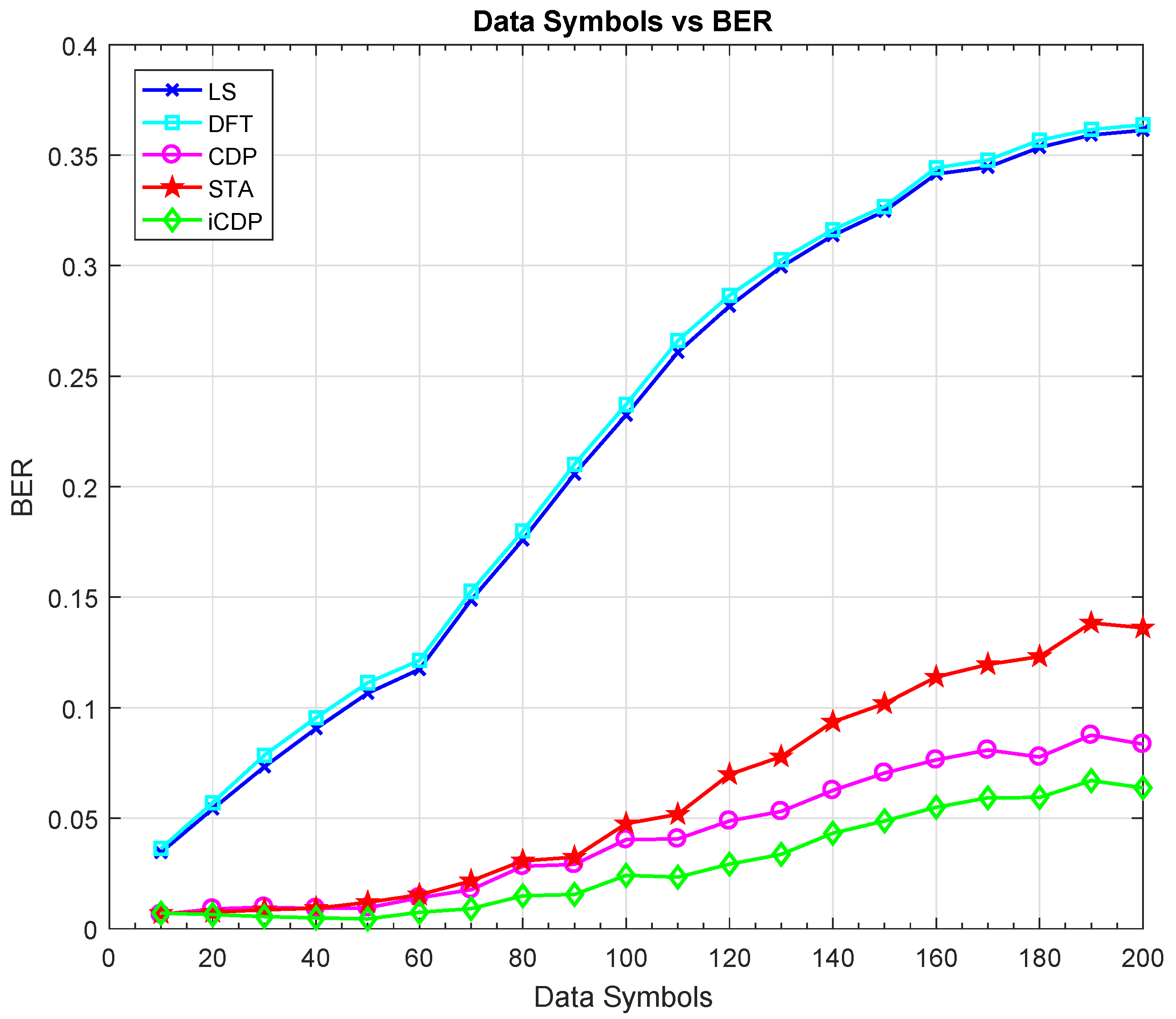
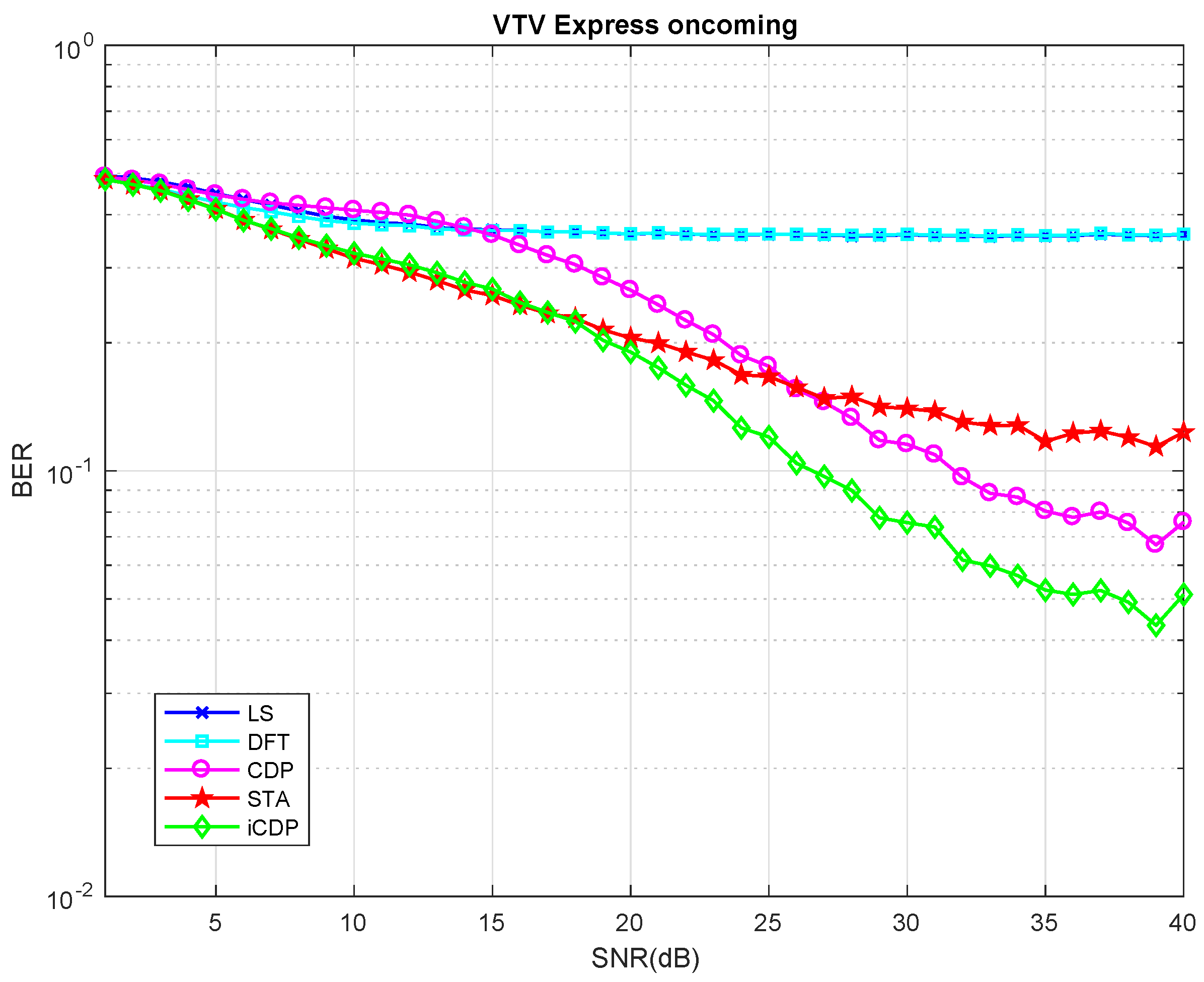
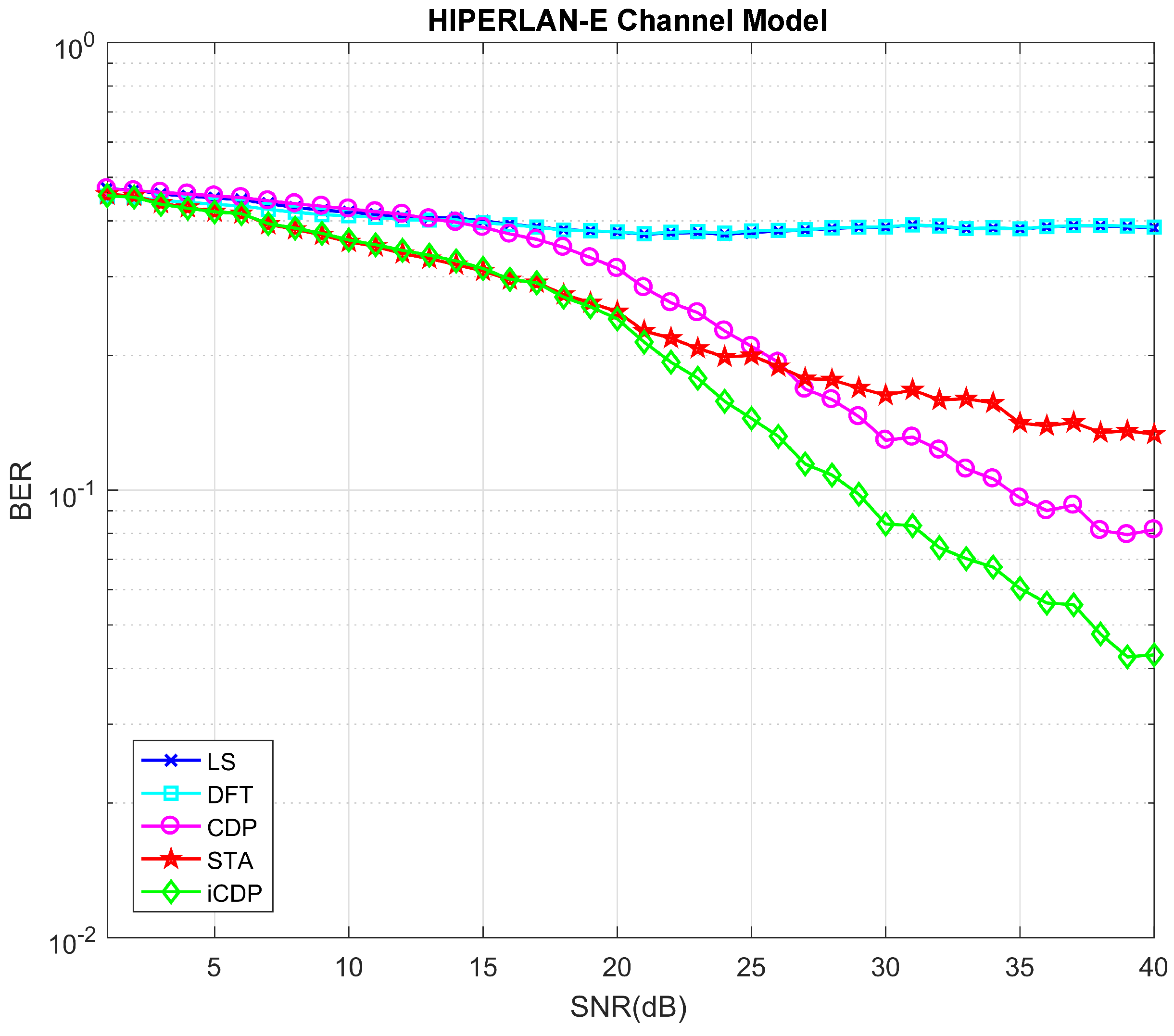
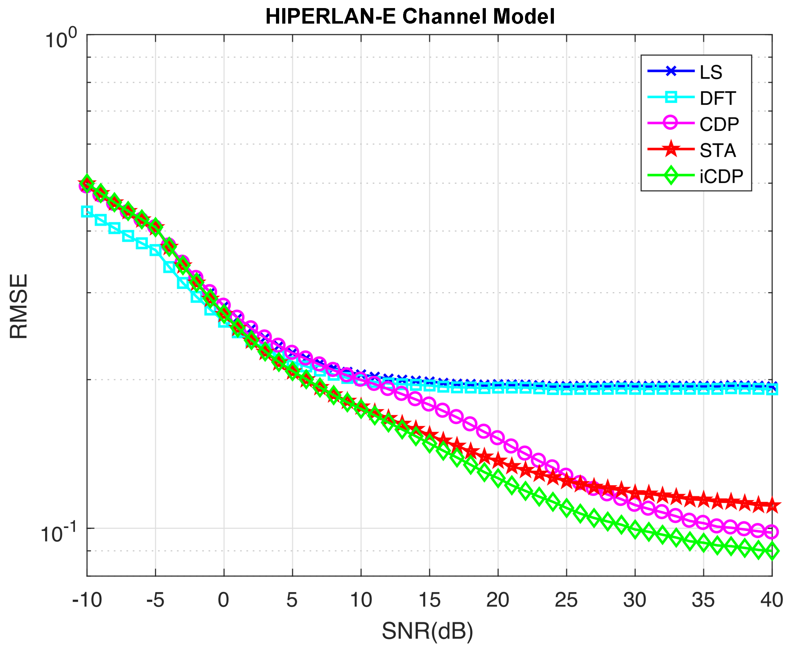
- The simulation results have demonstrated the performance improvement over CDP and spatial temporal-averaging (STA) schemes for V2V communications.
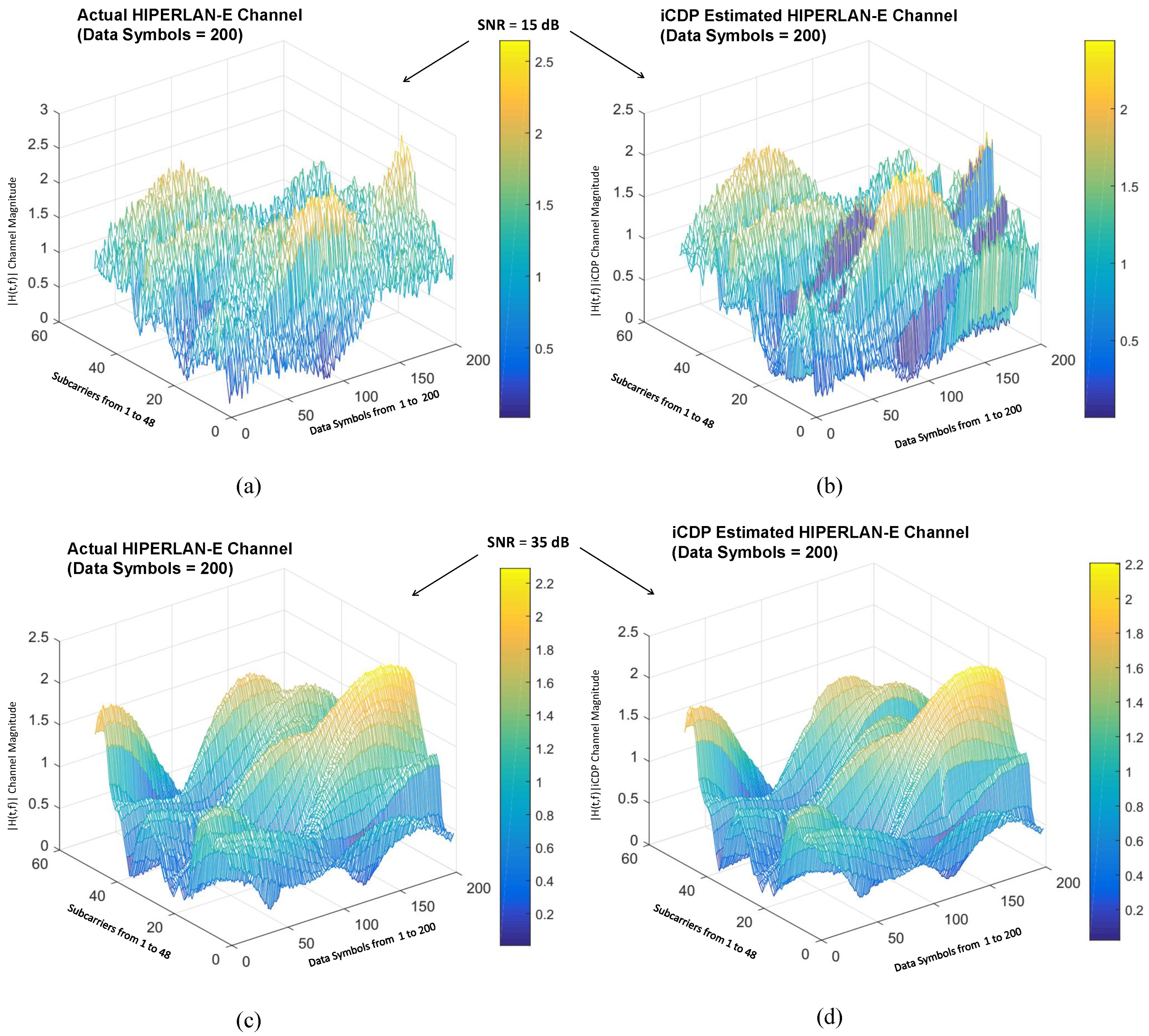
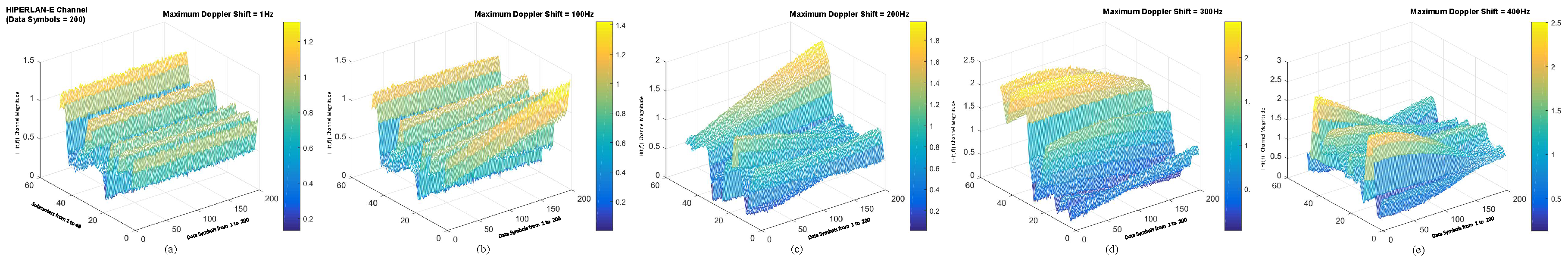
- We have also presented an intuitive visualization of the V2V channel model which is used in the evaluation of the proposed scheme.
2. System Model of the IEEE 802.11p
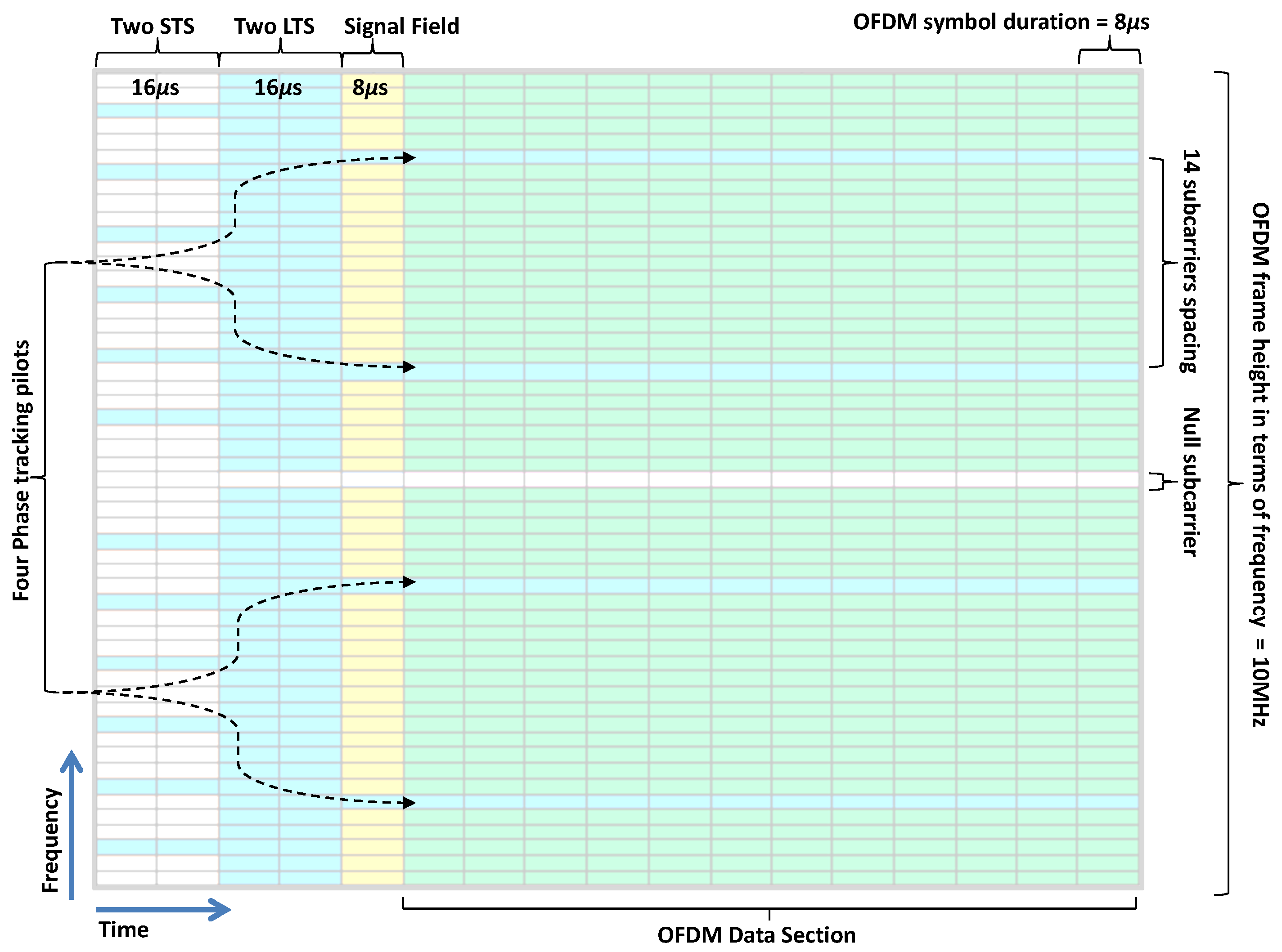
2.1. OFDM Frame of IEEE 802.11p
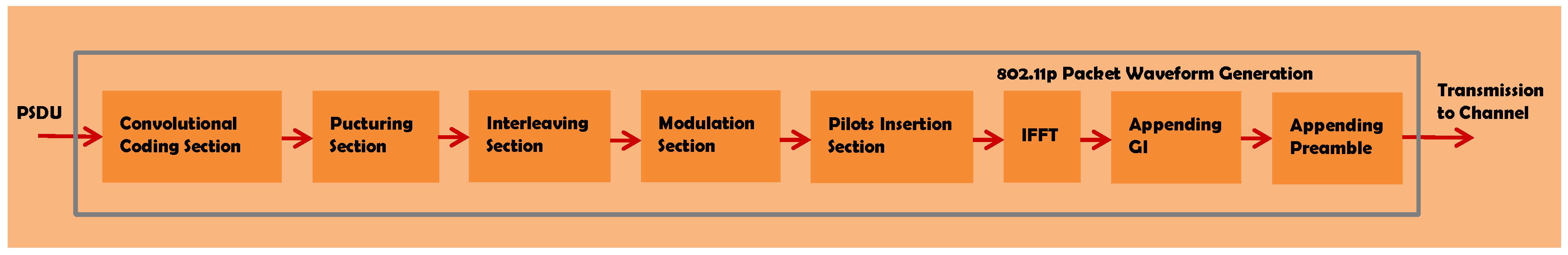
2.2. Transmitter Model
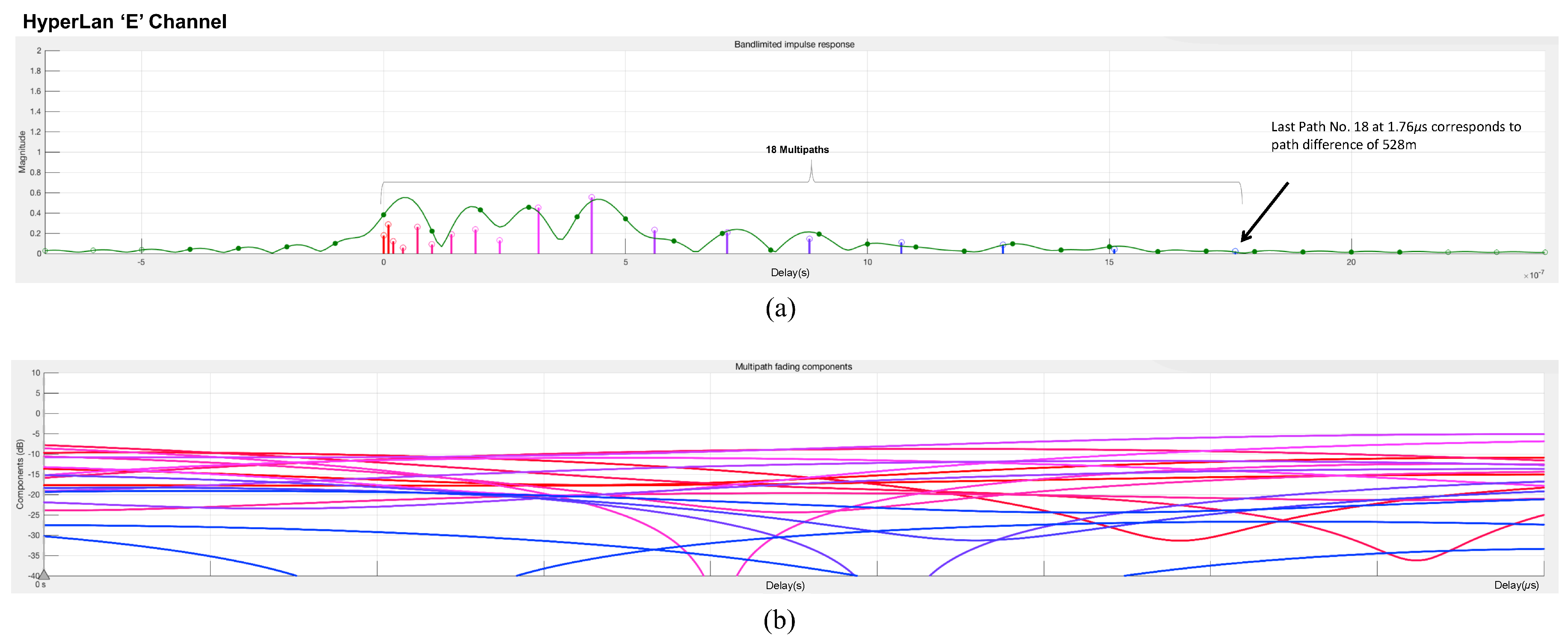
2.3. Channel Model
3. Overview of Current Channel Estimation Schemes
3.1. Scenario 1: Modification in IEEE 802.11p
3.1.1. The Midamble Based Channel Estimation Scheme (MBCE)
3.1.2. Time Domain Least Square Estimation (TDLSE) Scheme
3.2. Scenario 2: Remain the Structure of the IEEE 802.11p
3.2.1. Wiener Filter (WF) Based Scheme
3.2.2. Generalized Discrete Prolate Spheroidal (GDPS) Sequences Based Scheme
3.2.3. Spectral-Temporal Averaging (STA) Based Scheme
3.2.4. Pseudo-Pilot Based Scheme
3.2.5. DFT Based Scheme
3.2.6. CDP Based Scheme
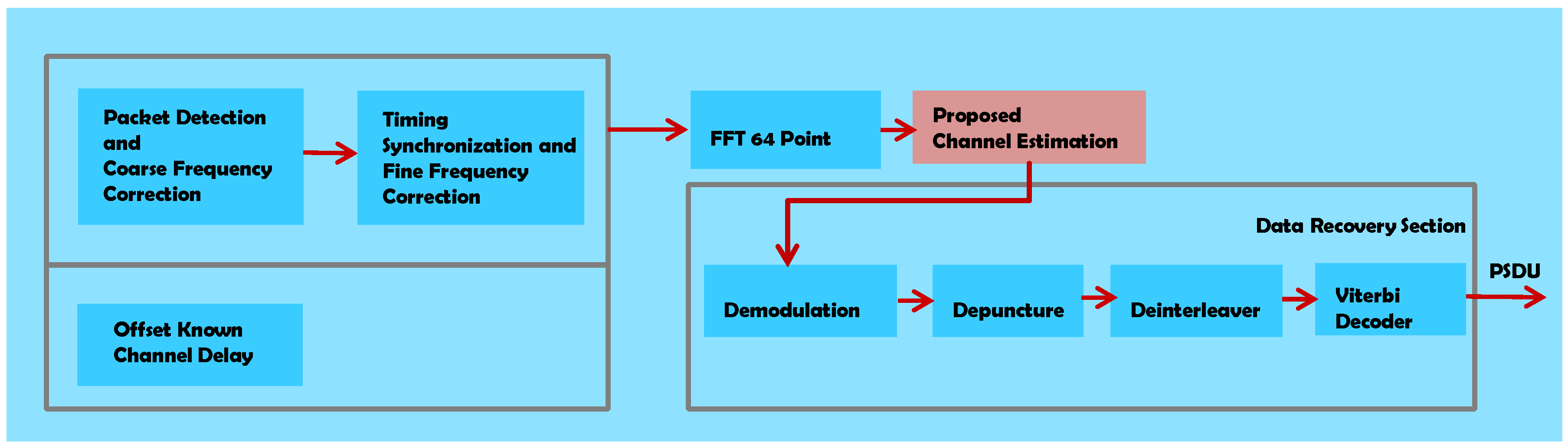
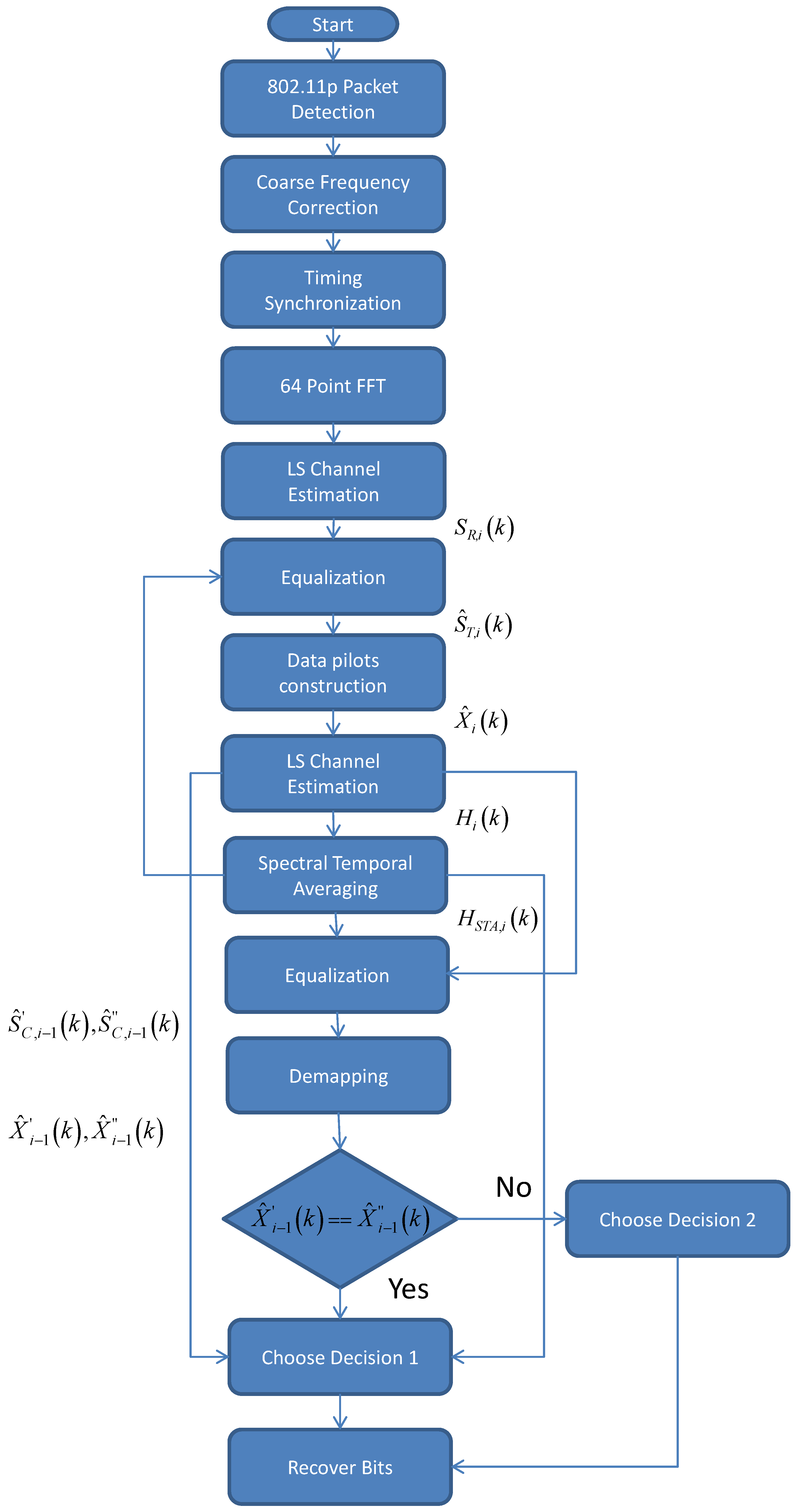
4. The Proposed Scheme
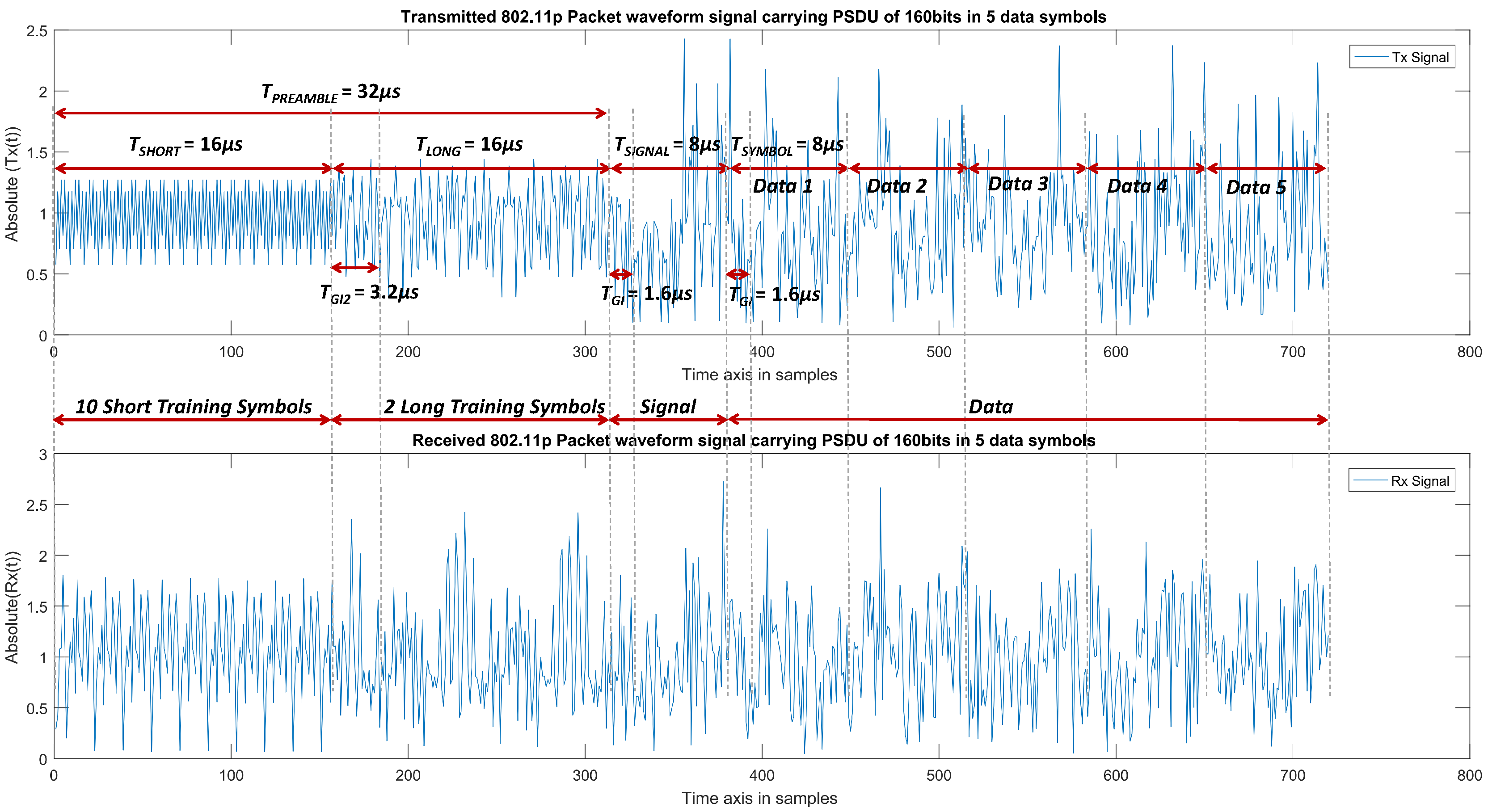
5. Simulation Results and Analysis
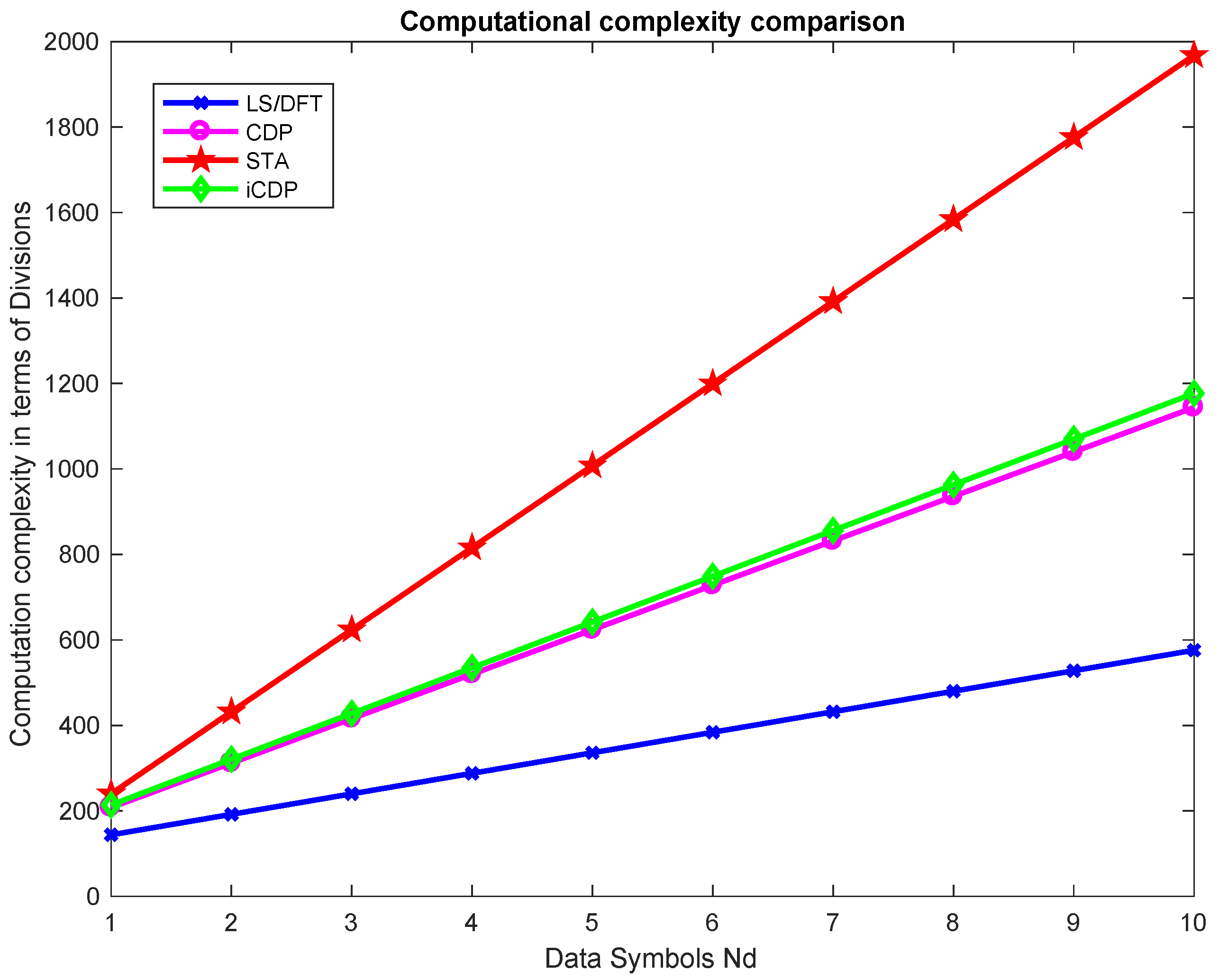
Computational Complexity
6. Issues and Future Work
7. Conclusions
8. Materials and Methods
Author Contributions
Funding
Acknowledgments
Conflicts of Interest
Abbreviations
| BER | Bit Error Rate |
| CDP | Constructed data pilots |
| DFT | Discrete Fourier Transform |
| DPS | Generalized Discrete Prolate Spheroidal |
| DSRC | Dedicated Short Range Communications |
| GI | Guard Interval |
| iCDP | Improved constructed data piloted |
| LS | Least square estimation |
| LTS | Long Training Symbols |
| MBCE | The Midamble Based Channel Estimation Scheme |
| MCS | Modulation Coding Scheme |
| NLOS | Non line of sight |
| OFDM | Orthogonal frequency division multiplexing |
| PHY | Physical |
| PLCP | Physical layer convergence procedure |
| STS | Short Training Symbols |
| STA | Spatial temporal Averaging |
| TDL | Tapped Delay Line |
| TDLSE | Time Domain Least Square Estimation Scheme |
| VTV | Vehicle to vehicle |
| WSSUS | Wide sense stationary uncorrelated scattering |
References
- IEEE Standard for Information Technology Telecommunications and Information Exchange Between Systems Local and Metropolitan Area Networks Specific Requirements Part 11, Wireless LAN Medium Access Control and Physical Layer Specifications; IEEE Standard 802.11p; IEEE: Piscataway, NJ, USA, 2010.
- Patra, S.; Veelaert, P.; Calafate, C.T.; Cano, J.C.; Zamora, W.; Manzoni, P.; Gonzalez, F. A Forward Collision Warning System for Smartphones Using Image Processing and V2V Communication. Sensors 2018, 18, 2672. [Google Scholar] [CrossRef] [PubMed]
- Hartenstein, H.; Laberteaux, K.P.T. A tutorial survey on vehicular ad hoc networks. IEEE Commun. Mag. 2008, 46, 32–58. [Google Scholar] [CrossRef]
- Li, Z.; Bai, F.; Fernandez, J.A.; Kumar, B.V.K.V. Tentpoles Scheme: A Data-Aided Channel Estimation Mechanism for Achieving Reliable Vehicle-to-Vehicle Communications. IEEE Trans. Wirel. Commun. 2015, 14, 2487–2499. [Google Scholar] [CrossRef]
- Zhao, Z.; Cheng, X.; Wen, M.; Jiao, B.; Wang, C.-X. Channel Estimation Schemes for IEEE 802.11p Standard. IEEE Trans. Intell. Transp. Syst. 2013, 5, 38–49. [Google Scholar]
- Mishra, K.V.; Eldar, Y.C. Sub-Nyquist channel estimation over IEEE 802.11ad link. In Proceedings of the IEEE International Conference on Sampling Theory and Applications (SampTA), Tallin, Estonia, 3–7 July 2017. [Google Scholar]
- Wang, T.; Hussain, A.; Bhutta, M.N.; Cao, Y. Enabling bidirectional traffic mobility for ITS simulation in smart city environments. Future Gener. Comput. Syst. 2018, 92, 342–356. [Google Scholar] [CrossRef]
- Choi, J.Y.; Mun, C.; Yook, J.G. Adaptive Channel Estimation Based on a Decision Method Using a Long Preamble for the IEEE 802.11p. In Proceedings of the IEEE 85th Vehicular Technology Conference (VTC Spring), Sydney, NSW, Australia, 4–7 June 2017. [Google Scholar]
- Yang, Y.; Fei, D.; Dang, S. Inter-Vehicle Cooperation Channel Estimation for IEEE 802.11p V2I Communications. IEEE J. Commun. Netw. 2017, 19, 227–238. [Google Scholar]
- Kim, S.I.; Oh, H.S.; Choi, H.K. Mid-amble aided OFDM performance analysis in high mobility vehicular channel. In Proceedings of the 2008 IEEE Intelligent Vehicles Symposium, Eindhoven, The Netherlands, 4–6 June 2008; pp. 751–754. [Google Scholar]
- Cho, W.; Kim, S.I.; Choi, H.K.; Oh, H.S.; Kwak, D.Y. Performance evaluation of V2V/V2I communications: The effect of midamble insertion. In Proceedings of the 2009 1st International Conference on Wireless Communication, Vehicular Technology, Information Theory and Aerospace & Electronic Systems Technology, Aalborg, Denmark, 17–20 May 2009; pp. 793–797. [Google Scholar]
- Lin, C.; Sun, C.; Lin, J.; Chen, B. Performance evaluations of channel estimations in IEEE 802.11p environments. In Proceedings of the 2009 International Conference on Ultra Modern Telecommunications & Workshops, St. Petersburg, Russia, 12–14 October 2009; pp. 1–5. [Google Scholar]
- Lin, C.; Lin, J. Novel channel estimation techniques in IEEE 802.11p environments. In Proceedings of the 2010 IEEE 71st Vehicular Technology Conference, Taipei, Taiwan, 16–19 May 2010; pp. 1–5. [Google Scholar]
- Nuckelt, J.; Schack, M.; Kurner, T. Performance Evaluation of wiener filter designs for channel estimation in vehicular environments. In Proceedings of the 2011 IEEE Vehicular Technology Conference (VTC Fall), San Francisco, CA, USA, 5–8 September 2011; pp. 1–5. [Google Scholar]
- Zemen, T.; Bernad, L.; Czink, N.; Molisch, A.F. Iterative time-variant channel estimation for 802.11p using generalized discrete prolate spheroidal sequences. IEEE Trans. Veh. Technol. 2012, 61, 1222–1233. [Google Scholar] [CrossRef]
- Bourdoux, A.; Cappelle, H.; Dejonghe, A. Channel tracking for fast time-varying channels in IEEE802.11p systems. In Proceedings of the 2011 IEEE Global Telecommunications Conference-GLOBECOM, Kathmandu, Nepal, 5–9 December 2011; pp. 1–6. [Google Scholar]
- Wang, C.X.; Cheng, X.; Laurenson, D.I. Vehicle-to-vehicle channel modeling and measurements: Recent advances and future challenges. IEEE Commun. Mag. 2009, 47, 96–103. [Google Scholar] [CrossRef]
- Cheng, X.; Wang, C.X.; Laurenson, D.I.; Salous, S.; Vasilakos, A.V. An adaptive geometry-based stochastic model for non-isotropic MIMO mobile-to-mobile channels. IEEE Trans. Wirel. Commun. 2009, 8, 4824–4835. [Google Scholar] [CrossRef]
- Cheng, X.; Wang, C.X.; Wang, H.; Gao, X.; You, X.; Yuan, D.; Ai, B.; Huo, Q.; Song, L.; Jiao, B. Cooperative MIMO channel modeling and multi-link spatial correlation properties. IEEE J. Sel. Areas Commun. 2012, 30, 388–396. [Google Scholar] [CrossRef]
- Cheng, X.; Wang, C.X.; Ai, B.; Aggoune, H. Envelope level crossing rate and average fade duration of non-isotropic vehicle-to-vehicle ricean fading channels. IEEE Trans. Intell. Trans. Syst. 2013, 99, 1–11. [Google Scholar]
- Ge, X.; Huang, K.; Wang, C.X.; Hong, X.; Yang, X. Capacity analysis of a multi-cell multi-antenna cooperative cellular network with co-channel interference. IEEE Trans. Wirel. Commun. 2011, 10, 3298–3309. [Google Scholar] [CrossRef]
- Wang, C.X.; Hong, X.; Ge, X.; Cheng, X.; Zhang, G.; Thompson, J.S. Cooperative MIMO channel models: A survey. IEEE Commun. Mag. 2010, 48, 80–87. [Google Scholar] [CrossRef]
- Cheng, X.; Yao, Q.; Wang, C.X.; Ai, B.; Stuber, G.L.; Yuan, D.; Jiao, B. An improved parameter computation method for a MIMO V2V rayleigh fading channel simulator under non-isotropic scattering environments. IEEE Commun. Lett. 2013, 17, 265–268. [Google Scholar] [CrossRef]
- Qu, F.; Yang, L. On the estimation of doubly selective fading channels. IEEE Trans. Wireless Commun. 2010, 9, 1261–1265. [Google Scholar] [CrossRef]
- Acosta-Marum, G. Measurement, Modeling, and OFDM Synchronization for the Wideband Mobile-to-Mobile Channel. Ph.D. Thesis, Georgia Institute of Technology, Atlanta, GA, USA, 2007. [Google Scholar]
- Sen, I.; Matolak, D.W. Vehicle-vehicle channel models for the 5 GHz band. IEEE Trans. Intell. Trans. Syst. 2008, 9, 235–245. [Google Scholar] [CrossRef]
- Cheng, X.; Yao, Q.; Wen, M.; Wang, C.-X.; Song, L.; Jiao, B. Wideband channel modeling and ICI cancellation for vehicle-to-vehicle communication systems. IEEE J. Sel. Areas Commun. 2013, 31, 434–448. [Google Scholar] [CrossRef]
- ETSI. 2015. Available online: http://www.etsi.org/technologies-clusters/technologies/intelligent-transport/ (accessed on 2 January 2018).
- Acosta-Marum, G.; Ingram, M.A. Six time-and frequency-selective empirical channel models for vehicular wireless LANs. IEEE Veh. Technol. Mag. 2007, 2, 4–11. [Google Scholar] [CrossRef]
- Muck, M.; de Courville, M.; Debbah, M.; Duhamel, P. A pseudo random postfix OFDM modulator and inherent channel estimation techniques. In Proceedings of the GLOBECOM ’03. IEEE Global Telecommunications Conference (IEEE Cat. No. 03CH37489), San Francisco, CA, USA, 1–5 December 2003; pp. 2380–2384. [Google Scholar]
- Lin, J. Channel estimation assisted by postfixed pseudo-noise se- quences padded with null samples for mobile OFDM communications. In Proceedings of the 2008 IEEE Wireless Communications and Networking Conference, Las Vegas, NV, USA, 31 March–3 April 2008; pp. 846–851. [Google Scholar]
- Lin, J. Least-squares channel estimation for mobile OFDM communication on time-varying frequency-selective fading channels. IEEE Trans. Veh. Tech. 2008, 57, 3538–3550. [Google Scholar]
- Lin, J.; Lin, C. LS channel estimation assisted from chirp sequences in OFDM communications. In Proceedings of the 2009 1st International Conference on Wireless Communication, Vehicular Technology, Information Theory and Aerospace & Electronic Systems Technology, Aalborg, Denmark, 17–20 May 2009; pp. 222–226. [Google Scholar]
- Ren, G.; Zhang, H.; Chang, Y. SNR estimation algorithm based on the preamble for OFDM systems in frequency selective channels. IEEE Trans. Commun. 2009, 57, 2230–2234. [Google Scholar] [CrossRef]
- Zemen, T.; Mecklenbrauker, C.F. Time-variant channel estimation using discrete prolate spheroidal sequences. IEEE Trans. Signal Process. 2005, 53, 3597–3607. [Google Scholar] [CrossRef]
- Fernandez, J.A.; Borries, K.; Cheng, L.; Kumar, B.V.K.V.; Stancil, D.D.; Bai, F. Performance of the 802.11p Physical layer in vehicle-to-vehicle environments. IEEE Trans. Veh. Technol. 2012, 61, 3–14. [Google Scholar] [CrossRef]
- Chang, M.; Hsieh, T. Detection of OFDM signals in fast fading with low-density pilot symbols. In Proceedings of the 2007 IEEE Wireless Communications and Networking Conference, Kowloon, China, 11–15 March 2007; pp. 1422–1427. [Google Scholar]
- Chang, M.; Hsieh, T. Detection of OFDM signals in fast-varying channels with low-density pilot symbols. IEEE Trans. Veh. Tech. 2008, 57, 859–872. [Google Scholar] [CrossRef]
- Chang, M.; Su, Y. Model-based channel estimation for OFDM signals in rayleigh fading. IEEE Trans. Commun. 2002, 50, 540–544. [Google Scholar] [CrossRef]
- Chang, M. A new derivation of least-squares-fitting principle for OFDM channel estimation. IEEE Trans. Wirel. Commun. 2006, 5, 726–731. [Google Scholar] [CrossRef]
- Kang, Y.; Kim, K.; Park, H. Efficient DFT-based channel estimation for OFDM systems on multipath channels. IET Commun. 2007, 1, 197–202. [Google Scholar] [CrossRef]
- Chiueh, T.-D.; Tsai, P.-Y. OFDM Baseband Receiver Design for Wireless Communications; John Wiley and Sons: Singapore, 2007. [Google Scholar]
- Cao, Y.; Wang, T.; Kaiwartya, O.; Min, G.; Ahmad, N.; Abdullah, A.H. An EV Charging Management System Concerning Drivers Trip Duration and Mobility Uncertainty. IEEE Trans. Syst. Man Cybern. Syst. 2018, 48, 596–607. [Google Scholar] [CrossRef]


| Parameter | Values |
|---|---|
| FFT size | 64 |
| FFT period | 6.4 s |
| Symbol duration | 8.0 s |
| GI duration | 1.6 s |
| Total subcarriers | 52 |
| Pilot subcarriers | 4 |
| Data subcarriers | 48 |
| Code Rate | |
| Modulation Schemes | BPSK, QPSK, 16QAM, 64QAM |
| Bit Rate | 3, 4.5, 6, 9, 12, 18, 24, 27 |
| Frequency spacing of subcarriers | 156.25 KHz |
| Error correction coding | k = 7 (64 states) convolution code |
| Bandwidth | 10 MHz |
| Channel Model | Doppler Shift (Hz) | Multipaths | Velocity (km/h) | Average Path Gains (dB) | Path Delays (ns) |
|---|---|---|---|---|---|
| VTV Express Oncoming | 1000–1200 | 11 | 104 | [0, 0, 0, −6.3, −6.3, −25.1, −25.1, −25.1, −22.7, −22.7, −22.7] | [0, 1, 2, 100, 101, 200, 201, 202, 300, 301, 302] |
| RTV Expressway | 600–700 | 12 | 104 | [0, 0, 0, −9.3, −9.3, −9.3, −20.3, −20.3, −21.3, −21.3, −28.8, −28.8] | [0, 1, 2, 100, 101, 102, 200, 201, 300, 301, 400, 401] |
| VTV Express SDWW | 900–1150 | 12 | 104 | [0, 0, −11.2, −11.2, −19, −21.9, −25.3, −25.3, −24.4, −28.0, −26.1, −26.1] | [0, 1, 100, 101, 200, 300, 400, 401, 500, 600, 700, 701] |
| RTV Urban Canyon | 300 | 12 | 32–48 | [0, 0, 0, −11.5, −11.5, −11.5, −19.0, −19.0, −25.6, −25.6, −28.1, −28.1] | [0, 1, 2, 100, 101, 102, 200, 201, 300, 301, 500, 501] |
| RTV Suburban street | 300–500 | 12 | 32–48 | [0, 0, −9.3, −9.3, −14, −14, −18, −18, −19.4, −24.9, −27.5, −29.8] | [0, 1, 100, 101, 200, 201, 300, 301, 400, 500, 600, 700] |
| VTV Urban Canyon Oncoming | 400–500 | 12 | 32–48 | [0, 0, −10, −10, −10, −17.8, −17.8, −17.8, −21.1, −21.1, −26.3, −26.3] | [0, 1, 100, 101, 102, 200, 201, 202, 300, 301, 400, 401] |
| HIPERLAN−E | 1000–1200 | 18 | 109.83 | [−4.9, −5.1, −5.2, −0.8, −1.3, −1.9, −0.3, −1.2, −2.1, 0.0, −1.9, −2.8, −5.4, −7.3, −10.6, −13.4, −17.4, −20.9] | [0, 10, 20, 40, 70, 100, 140, 190, 240, 320, 430, 560, 710, 880, 1070, 1280, 1510, 1760] |
| Scheme | SM Requirement | CSI Requirement | CCL | PL | Compatibility |
|---|---|---|---|---|---|
| STA | No | Yes | 0.3 | 0.2 | Invariant |
| MBCE | Yes | No | 0.2 | 0.1–0.3 | Reduced |
| TDLSE | Yes | No | 0.2 | 0.2 | Reduced |
| LS | No | No | 0.1 | 0.5 | Invariant |
| WF | No | Yes | 0.3 | 0.3 | Invariant |
| GDPS | No | Yes | 0.5 | 0.3 | Invariant |
| Improved GDPS | Yes | Yes | 0.4 | 0.3 | Invariant |
| DD | No | Yes | 0.5 | 0.3 | Invariant |
| DD Lossless reduction | No | Yes | 0.4 | 0.3 | Invariant |
| DD Lossy reduction | No | Yes | 0.5 | 0.3–0.4 | Invariant |
| Pseudo-pilot | No | Yes | 0.5 | 0.3–0.4 | Invariant |
| CDP | No | Yes | 0.2 | 0.1–0.2 | Invariant |
| Proposed | No | Yes | 0.3 | 0.1 | Invariant |
| Parameter | Value | 10 MHz Channel Bandwidth |
|---|---|---|
| Number of data subcarriers | 48 | 48 |
| Number of pilot subcarriers | 4 | 4 |
| Number of total subcarriers | + | 52 |
| Subcarrier frequency spacing | 10 MHz/64 | 0.15625 MHz |
| : FFT, IFFT period | 1/ | 6.4 s |
| : GI duration | / 4 | 1.6 s |
| : Duration of the Signal section | + | 8 s |
| : Training symbol GI duration | / 2 | 3.2 s |
| : Symbol duration | + | 8 s |
| : STS duration | 10 × / 4 | 16 s |
| : STS duration | 2 × + | 16 s |
| : Duration of PLCP preamble | + | 32 s |
| Scheme | Divisions | Multiplications | Additions | Subtractions |
|---|---|---|---|---|
| LS | 48 + 96 | - | 48 | - |
| DFT | 48 + 96 | - | 48 | - |
| STA | 104 + 104 | 148 − 2 | 52 + 2( + 1)(52 − 2) | 48 |
| CDP | 192 + 48 | - | 48 | - |
| iCDP | 104 + 104 | 144 | 52+240 | 48 |
© 2018 by the authors. Licensee MDPI, Basel, Switzerland. This article is an open access article distributed under the terms and conditions of the Creative Commons Attribution (CC BY) license (http://creativecommons.org/licenses/by/4.0/).
Share and Cite
Wang, T.; Hussain, A.; Cao, Y.; Gulomjon, S. An Improved Channel Estimation Technique for IEEE 802.11p Standard in Vehicular Communications. Sensors 2019, 19, 98. https://doi.org/10.3390/s19010098
Wang T, Hussain A, Cao Y, Gulomjon S. An Improved Channel Estimation Technique for IEEE 802.11p Standard in Vehicular Communications. Sensors. 2019; 19(1):98. https://doi.org/10.3390/s19010098
Chicago/Turabian StyleWang, Tong, Azhar Hussain, Yue Cao, and Sangirov Gulomjon. 2019. "An Improved Channel Estimation Technique for IEEE 802.11p Standard in Vehicular Communications" Sensors 19, no. 1: 98. https://doi.org/10.3390/s19010098
APA StyleWang, T., Hussain, A., Cao, Y., & Gulomjon, S. (2019). An Improved Channel Estimation Technique for IEEE 802.11p Standard in Vehicular Communications. Sensors, 19(1), 98. https://doi.org/10.3390/s19010098